EP0842476B1 - A computer booking system - Google Patents
A computer booking system Download PDFInfo
- Publication number
- EP0842476B1 EP0842476B1 EP96922141A EP96922141A EP0842476B1 EP 0842476 B1 EP0842476 B1 EP 0842476B1 EP 96922141 A EP96922141 A EP 96922141A EP 96922141 A EP96922141 A EP 96922141A EP 0842476 B1 EP0842476 B1 EP 0842476B1
- Authority
- EP
- European Patent Office
- Prior art keywords
- node
- booking
- value
- list
- time
- Prior art date
- Legal status (The legal status is an assumption and is not a legal conclusion. Google has not performed a legal analysis and makes no representation as to the accuracy of the status listed.)
- Expired - Lifetime
Links
Images


Classifications
-
- H—ELECTRICITY
- H04—ELECTRIC COMMUNICATION TECHNIQUE
- H04L—TRANSMISSION OF DIGITAL INFORMATION, e.g. TELEGRAPHIC COMMUNICATION
- H04L41/00—Arrangements for maintenance, administration or management of data switching networks, e.g. of packet switching networks
- H04L41/18—Delegation of network management function, e.g. customer network management [CNM]
-
- H—ELECTRICITY
- H04—ELECTRIC COMMUNICATION TECHNIQUE
- H04J—MULTIPLEX COMMUNICATION
- H04J2203/00—Aspects of optical multiplex systems other than those covered by H04J14/05 and H04J14/07
- H04J2203/0001—Provisions for broadband connections in integrated services digital network using frames of the Optical Transport Network [OTN] or using synchronous transfer mode [STM], e.g. SONET, SDH
- H04J2203/0064—Admission Control
- H04J2203/0067—Resource management and allocation
Definitions
- This invention relates to a computer booking system for booking resources to users of the resources and particularly, but not exclusively, to a computer booking system for booking resources of a telecommunications network to users of the network. This invention also relates to a method of operating a computer booking system for booking resources to users.
- the problem of providing a booking system for booking resources which has to cope with a relatively small number of requests for use of the resources is easy to solve.
- Such a booking system may be implemented in either a paper-based form or a computer-based form.
- it is sometimes required to provide a booking system for booking resources which has to cope with a relatively large number of requests for use of the resources.
- it may be required to provide a booking system for booking individual channels of the network which has to cope with a large number of requests for use of the channels at various future time periods.
- the problem of providing such a booking system is not easy to solve.
- a computer booking system for booking individual ones of a set of resources to users of the resources, said computer booking system comprising:
- the meaning of the term "user” as used herein is intended to include equipment.
- the users may be other parts of the network, other networks, or terminal equipment belonging to individuals or organisations.
- a method of operating a computer booking system for booking individual ones of a set of resources to users of the resources comprising the steps of:
- the booking system of this invention provides a particularly elegant solution to the problem of providing a booking system for booking resources which can cope with a large number of requests for use of the resources.
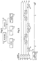
- FIG. 1 there are shown some of the elements of a telecommunications network. These elements include a pair of synchronous digital hierarchy (SDH) multiplexers 10, 11.
- the multiplexers 10, 11 form part of a network of multiplexers and associated asynchronous transfer mode (ATM) switches which are connected together so as to carry telecommunications traffic.
- the SDH multiplexer 10 receives and transmits telecommunications traffic on tributary links 12-15 and the multiplexer 11 receives and transmits traffic on tributary links 16-19. Between multiplexers 10 and 11, traffic is transmitted on a link 20.
- An SDH multiplexer is capable of receiving traffic on its tributary links of varying data rates.
- a set of channels will have already been combined by time division multiplexing.
- An SDH multiplexer subjects traffic which it receives on tributary links to time division multiplexing and transmits the traffic multiplexed in this way on a single outgoing link.
- a single link will thus carry a large number of individual channels.
- the maximum number of channels which can be carried between two multiplexers will depend upon the data rates of the channels and the data rate used in the transmission between the two multiplexers.
- two high order SDH multiplexers several hundred or even several thousand channels may be carried over a single link.
- the multiplexers 10, 11 are managed, respectively, by element managers 30, 31 and the element managers 30, 31 are managed by a network manager 32.
- the network manager 32 also manages other element managers which in turn manage other elements of the telecommunications network.
- the construction of element managers and network managers is well known to those skilled in the art and so the construction of the network manager 32 and element managers 30 and 31 will not be described in detail.
- Both network managers and element managers are implemented as computers.
- the main components of a computer comprise a central processing unit (CPU) 40, a store 41 which typically comprises both hard disk memory and random access memory (RAM), input/output ports 42, a display 43 which usually takes the form of a visual display unit and a keyboard 44 for receiving instructions from the operator.
- Store 41 holds the program for controlling the computer and stores data.
- Each of the multiplexers 10 and 11 is controlled by a computer which forms part of the multiplexer.
- the network shown in Figure 1 includes a booking system for holding data relating to the booking of the individual channels between multiplexers 10 and 11 to the users of the channels.
- the users of the channels may be other parts of the network, other networks, or terminal equipment belonging to individuals or organisations.
- the booking system could be implemented as part of the network manager 32, part of one of the element managers 30 and 31, or as part of the computer controlling one of the multiplexers 10 and 11.
- the booking system is implemented as part of network manager 32.
- the program for controlling the booking system forms part of the program of network manager 32 and the store 41 of network manager 32 is responsible for storing the data.
- FIG. 3 this illustrates the data structures used in the booking system.
- These data structures comprise a set of data nodes 50, a time structure 52 and a value structure 54.
- the data nodes 50 contain data relating to the individual bookings, a pair of nodes being used for each booking.
- Each node contains data either relating to the beginning of a booking of a channel or data relating to the end of a booking of channel.
- nodes Aon and Aoff respectively, contain data relating to the beginning and end of booking A.
- nodes Bon and Boff, nodes Con and Coff, and nodes Don and Doff contain data relating to bookings B, C and D.
- Figure 3 only shows a small number of data nodes 50 but in practice the booking system would contain a very much larger number of nodes.
- the nodes 50 are located in a single linked list (the time list) of nodes in which the nodes are arranged in time order.
- the linked list is indicated in Figure 3 by dashed line 56.
- Each of the nodes 50 is also located in a respective one of a set of lists (the value lists).
- Figure 3 shows four value lists and these are indicated by solid lines 58-61.
- the nodes Aon, Aoff, Con and Doff are on value list 58.
- Nodes Bon, Boff, Don and Coff are on value list 59.
- the value lists are arranged in order of rank.
- the value lists are equal in number to the number of channels which may be booked. However, the value lists are associated with the channels on a cumulative basis as bookings are made rather than on an actual basis.
- value lists 58-61 are associated with channels 1-4 on a cumulative basis.
- node Aon which is the node for the commencement of booking for booking A
- Node Bon which represents the commencement of the booking period for booking B
- the user will be allocated to one of the actual channels which is free, and this channel may or may not be actual channel 2.
- each new node is located on the value list of the lowest possible rank.
- Figure 3 shows only four value lists and thus the data structure shown in Figure 3 is suitable for booking only four channels.
- the booking system of the present invention is suitable for booking a much larger number of channels, for example several hundred or even several thousand channels, and so in practice there will be a much larger number of value lists.
- Figure 3 shows bookings over a short time period.
- the booking system of Figure 3 is suitable for making bookings over a long or indefinite time period. The booking system of Figure 3 is capable of dealing with a very large number of bookings.
- the time structure 52 points to the beginning of the time list 56.
- the value structure 54 is divided into four elements 65, 66, 67 and 68 which are associated, respectively, with value lists 58-61.
- elements 65-68 are associated, respectively, with the value lists for cumulative channels 1-4.
- numerals 1-4 have been written inside the blocks representing elements 65-68.
- nodes 50, time structure 52 and the individual elements of value structure 54 will now be described with reference to Figures 4 to 6.
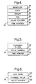
- the fields for each of the nodes 50 comprise an IDENTIFIER field 80, a USER field 81, an ON/OFF field 82, a TIME field 83, a VALUE POINTER field 84 and a TIME POINTER field 85.
- the IDENTIFIER field 80 contains the identifier for the node and the USER field 81 contains an identification of the user.
- the ON/OFF field 82 specifies whether the event associated with the node is the beginning or end of the booking. In field 82, if the event is the beginning of the booking, the field is set to a value ON. If the event is at the end of a booking, this field is set to a value OFF.
- a node which represents the beginning of a booking will be hereinafter referred as an ON node and a node which represents the end of a booking will be referred to as an OFF node.
- the TIME field 83 specifies the time at which the event occurs.
- the VALUE POINTER 84 points to the next node in the same value list and the TIME POINTER field 85 points to the next node on the time list 56.
- the details of the user could be stored separately from the node.
- the details of the event associated with the node could be stored separately.
- CHANNELS IN USE field 90 specifies the number of actual channels which are in use at the current time
- TOTAL NUMBER field 91 specifies the total number of channels on the link 20
- TIME POINTER field 92 points to the beginning of the time list 56.
- the LINK NAME field 100 contains the identifier for the link, which in the present example is link 20.
- the CHANNEL VALUE field 101 specifies the cumulative channel with which the element is associated. Thus, for example, in the case of the element 65, the CHANNEL VALUE field specifies channel 1.
- the VALUE POINTER field 102 points to the beginning of the value list with which the element is associated. Thus, for example, in the case of element 65, the VALUE POINTER field points to node Aon.
- the TIME POINTER field 92 of the time structure 52 is read. Then, the time list can be scanned from left to right (as viewed in Figure 3) by reading the TIME POINTER fields of the nodes. For example, after locating node Aon, the next node on the time list is found by reading the TIME POINTER field of this node.
- the TIME POINTER field of node Aon contains, in the present example, the identifier for node Bon.
- the field VALUE POINTER of the appropriate element of the value structure 54 is read. The value list can be scanned by reading the VALUE POINTER fields of the nodes.
- each node can be provided with a first pair of pointers for pointing, respectively, to the next node and the previous node in the same value list and a second pair of pointers for pointing, respectively, to the next node and the previous node in the time list.
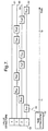
- Figure 3 shows the nodes which are necessary to specify bookings A to D and Figure 7 shows the addition of two further nodes, namely nodes Eon and Eoff, in order to make booking E.
- Booking E commences at time t1 and ends at time t2.
- An ON node is located on the value list for the cumulative channel number which is equal to the number of channels which will be in use immediately following commencement of the booking.
- node Eon is placed on the value list for cumulative channel 2.
- An OFF node is placed on the value list for the cumulative channel number which is equal to the number of channels which will be in use immediately before the end of the booking.
- node Eoff is placed on the value list for cumulative channel 3.
- each of the nodes between times t1 and t2 is raised onto a value list which is one value list higher in rank than its previous value list.
- nodes Aoff and Con are raised from the value list for cumulative channel 1 to the value list for cumulative channel 2.
- nodes Bon, Boff and Don are raised from the value list for cumulative channel 2 to the value for cumulative channel 3.
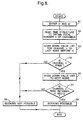
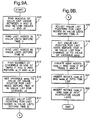
- the sub-routines for determining if a channel may be booked, making a new booking and removing an existing booking will now be described with reference to Figures 8 to 10.
- the sub-routines form part of the program of the booking system.
- the sub-routines will be described with reference to the examples shown in Figures 3 and 7.
- step S1 the operator of the booking system enters the desired beginning and end times of the booking, namely times t1 and t2.
- the sub-routine reads the time structure 52 to obtain the total number n of channels which may be booked.
- the link has four channels and so a value 4 is returned.
- step S3 the value list for cumulative channel n is scanned to the last node before time t1.
- the scanning operation proceeds no further than element 68 of value structure 54.
- step S4 it is determined if cumulative channel n is free before time t1. If channel n is not free at this time, the sub-routine proceeds with step S5 in which it is displayed to the user that a booking is not possible. The sub-routine ends after step S5.
- step S4 If it is found in step S4 that channel n is free, the sub-routine continues with step S6. In the example shown in Figure 3, as there are no nodes located on the value list for cumulative channel 4, the sub-routine goes from step S4 to step S6.
- step S6 the sub-routine scans down the value list for cumulative channel n to the next node. Then, in step S7, it is determined if channel n is free between times t1 and t2. If channel n is not free between these two times, the sub-routine jumps to step S5 so that the operator is informed that a booking is not possible. If in step S7 it is found that channel n is free between times t1 and t2, the sub-routine continues with step S8 in which it is displayed that a booking is possible. If there is at least one node before time t1, channel n will be free at time t1 if the last node is an OFF node. If there is also a node after time t1, that node will be an off node and channel n will be free between t1 and t2 if that OFF node is after time t2. The sub-routine ends after step S8.
- the sub-routine goes from step S7 to step S8 and the user is informed that a booking is possible.
- a step S12 the value list of highest rank and the value list of lowest rank on which nodes are located between times t1 and t2 are found. This is done by scanning along the time list between times t1 and t2. The numbers of the cumulative channels represented by these value lists of highest and lowest rank are returned as values v1 and v2. Thus, in the example of adding booking E, values v1 and v2 are, respectively, 2 and 1.
- step S13 the last nodes in the value lists before time t1 are found for each value list in turn commencing with the value list for channel (v1 + 1) and ending with the value list for the cumulative channel v2.
- an element of the value structure 54 is identified as a node.
- the elements 67 and 66 of the value structure and node Aon are identified.
- step S14 the last nodes in the value lists before time t2 are found for each value list in turn commencing with the value list for cumulative channel (v1 + 1) and ending with the value list for the cumulative channel v2.
- element 67 of the value structure and nodes Don and Con are identified.
- step S15 the number of channels scheduled to be in use at times t1 and t2 are found and stored as values at at_t1 and at at_t2.
- the value at_t1 is found by scanning along the time list to the first node after time t1. Then, the value list on which this node is located is scanned to its end. In the case of the last node of the value list, the VALUE POINTER field holds the number of the channel it represents. If the first node after time t1 is an OFF node, then the number of the channel which the value list represents is equal to the number of channels scheduled to be used at time t1. If this node is an ON node, then the number of channels in use will be one less than this. The number of channels scheduled to be in use at time t2 is found in analogous manner.
- the number of channels scheduled to be used at time t1 is one and the number of channels scheduled to be in use at time t2 is two.
- a variable temp is set to the value of the VALUE POINTER field for the last node before time t2 in the value list for channel v2.
- the variable temp is set to the value of the VALUE POINTER field of the node Con.
- the value list pointers for the last nodes in the value lists before time t2 are adjusted. This operation commences with the last node in the value list for channel v2 before time t2 and ends with the last node in the value list for channel v1 before time t2. For each node, the VALUE POINTER field is set to the value of the VALUE POINTER field of the last node before t2 in the value list of one rank higher.
- the VALUE POINTER field of node Con is set to the value of the VALUE POINTER field of node Don.
- the VALUE POINTER field of node Don is set to the value of the VALUE POINTER field of the element 67 of the value structure for channel 3.
- the value list pointers for the last nodes in the value lists before time t1 are adjusted. This operation commences with the last node in the value list for channel (v1 + 1) before time t1 and ends with the last node in the value list for channel (v2 + 1) before time t1.
- the VALUE POINTER is set to the value of the VALUE POINTER field of the last node before t1 in the value list of one rank lower.
- the VALUE POINTER field of the element 67 of the value structure for channel 3 is set to the value of the VALUE POINTER field of the element 66 of the value structure for channel 2.
- the value of the VALUE POINTER field of the element 66 of the value structure for channel 2 is set to the value of the VALUE POINTER field of node Aon.
- step S19 the VALUE POINTER field for the last node before time t1 in the value list for channel v2 is set to the value of the variable temp.
- the VALUE POINTER field of node Aon is set to the variable temp.
- each of the nodes between times t1 and t2 is raised into a value list of one rank higher than its previous value list.
- new nodes node_t1 and node_t2 are created as the ON and OFF nodes for the new booking.
- the IDENTIFIER field is set to node_t1
- the USER field is set to an identifier for the intended user of the channel for the new booking
- the ON/OFF field is set to ON
- the TIME field is set to time t1.
- the IDENTIFIER field is set to node_t2
- the USER field is set to the identifier for the intended user
- the ON/OFF field is set to OFF and the TIME field is set to time t2.
- the new nodes node_t1 and node_t2 are, in fact, nodes Eon and Eoff.
- node node_t1 and node_t2 are inserted into the time list 56 at times t1 and t2, if appropriate, after any other node or nodes which may be already located in the time list at one or both of these times.
- node Eon is inserted in the time list between nodes Aon and Bon and node Eoff is inserted into the time list between Don and Coff.
- node node_t1 and node_t2 are inserted into their respective value lists.
- node_t2 this is achieved by setting the VALUE POINTER field of node_t2 to the value of the VALUE POINTER field of the last node currently located on the value list for channel (at_t2 + 1) before time t2. Also, the VALUE POINTER field of the last node before time t2 for channel (at_t2 + 1) is set to the identifier for node_t2.
- the VALUE POINTER field of this node is set to the value of the VALUE POINTER field of the last node before time t1 on the channel list for channel (at_t1 + 1). Also, the VALUE POINTER field for the last node before t1 on the value list for channel (at_t1 + 1) is set to point to the node node_t1.
- nodes Eon and Eoff are located respectively on the value lists for channels 2 and 3.
- the sub-routine shown in Figure 9 may include a facility to make a series of bookings for a user, for example a booking for a particular period in each week for a desired number of weeks.
- FIG 10 there is shown the flow chart for the sub-routine for removing an existing booking of a channel from the user between times t1 and t2.
- the operation of this sub-routine will be described with reference to removing booking E and thus returning the booking structure from the arrangement shown in Figure 7 to that shown in Figure 3.
- the ON and OFF nodes for the booking are located by scanning down the time list. These nodes are designated as node_t1 and node_t2. If there are other nodes at t1 or t2, the value pointers of the nodes are adjusted so that nodes node_t1 and node_t2 are the last node in the value lists at each of these times. In the example of booking E, nodes Eon and Eoff are located.
- the bounds of usage of the value lists between times t1 and t2 are found and returned as values v1 and v2.
- the bounds of usage include the value list of highest rank and the value list of lowest rank on which nodes are located between times t1 and t2.
- the time period is considered to commence immediately after the node node_t1 and end immediately after the node node_t2.
- v1 and v2 have values 3 and 2.
- step S32 the last nodes are found in the value lists which are not after time t1. This operation is performed for the value lists between the value list for channel v1 and the channel list for value (v2-1). These include the node node_t1. In the example of removing booking E, in step S32 the element of the value structure for channel 3 and nodes Eon and Aon are found.
- step S33 the last node in the value lists not after time t2 are found for the same range of value lists as in step S32.
- the nodes which are found include node_t2.
- nodes Eoff, Con and Aon are found.
- step S34 the number of channels in use are found immediately after node node_t1 and immediately after the node node t2 and values at at_t1 and at_t2 are returned. These values are found by scanning along the time list. In the example of removing booking E, both values at_t1 and at_t2 are set to 2.
- a variable temp is set to the value of the value pointer for the last node not after time t2 on the value list for channel v1.
- the variable temp is set to the value of the value pointer for node Eoff which indicates that it is the last node in the value list for channel 3.
- a step S36 the value list pointers for the last nodes in the value lists not after time t2 are adjusted. This operation is performed for each value list commencing with the value list for channel v1 and ending with the value list for the channel v2. For each of these nodes, the VALUE POINTER field is set to the value of the VALUE POINTER field for the node not after time t2 in the value list of one rank lower.
- the value pointer of node Eoff is adjusted so that it points to node Coff and the value pointer of Con is adjusted so that it points to node Doff.
- the value pointers are adjusted for the last nodes in the value lists not after time t1. This operation is performed for the value lists which commence with the value list for channel (v2-1) and ending with the value list for the channel (v1-1). For each of these nodes, the VALUE POINTER field is set to the value of the VALUE POINTER field for the node not after t1 in the value list of one rank higher.
- the value pointer of node Aon points to node Aoff and the value pointer of node Eon points to node Bon.
- step S38 the VALUE POINTER field for the last node not after time t1 in the value list for channel v1 is set to the value of the variable temp.
- the element of the value structure for channel 3 indicates that this is the last node of the value list for channel 3.
- nodes node_t1 and node_t2 are removed from their respective value lists. This is achieved by adjusting the value pointer for the last node not after t1, and not node_t1 itself, in channel at_t1 to the value of the value pointer for node_t1. Also, the last node not after t2, and excluding node_t2 itself, is set to the value of the value pointer of node_t2.
- nodes node_t1 and node_t2 are removed from the time list.
- nodes node_t1 and node_t2 are removed from both the value lists and the time list.
- nodes Eon and Eoff are removed at this stage.
- a step S50 the sub-routine scans along the time list and finds the next node after the present time.
- step S51 it inspects the node to determine if it is an ON node or an OFF node. If it is an ON node, in a step S52, at the beginning of the booking period scheduled on the next node, it allocates one of the free channels to the user in whose name the booking is made.
- the sub-routine then returns to step S50 and scans along the time list to find the next node.
- step S51 If in step S51 it is found that the next node is an OFF node, the sub-routine jumps to step S53.
- the next node will specify a user who is presently using one of the channels and the time at which his booking is scheduled to end.
- step S53 the sub-routine removes this channel from the user.
- a channel is made available to the respective user at the beginning of each booking period and made unavailable to that user at the end of the booking period. It is to be noted that the channel which is made available to a user at the beginning of each booking period is one of the free actual channels and that the cumulative channel numbers used in the booking system are not used for this purpose.
- the flow charts of Figures 9 to 11 refer to bookings each of which commences and ends at fixed times.
- the booking system of the invention may also be used for making bookings each of which commences at a fixed time and continues indefinitely. When making such a booking, only an ON node is created.
- the booking system may also be used for booking of channels through one of the SDH multiplexers 10, 11.
- the booking system could be used for booking ports for a communications link.
- it could be used for booking items hired out by a hire company.
- the present invention is particularly suitable for holding data relating to the booking of individual ones of a set of resources when there are a large number of resources in the set.
- the process of scanning along the time and value lists can be relatively time consuming.
- a technique known as skip lists may be used.
- some of the nodes have additional pointers which look further ahead than the next node. For example, on average, half the nodes could be provided with only one pointer so that each of these nodes points only to the node directly in front of it. The other half of the nodes are provided with two pointers, one of which points to the next node and one of which points to two nodes ahead.
Landscapes
- Engineering & Computer Science (AREA)
- Computer Networks & Wireless Communication (AREA)
- Signal Processing (AREA)
- Management, Administration, Business Operations System, And Electronic Commerce (AREA)
- Data Exchanges In Wide-Area Networks (AREA)
- Computer And Data Communications (AREA)
Priority Applications (1)
| Application Number | Priority Date | Filing Date | Title |
|---|---|---|---|
| EP96922141A EP0842476B1 (en) | 1995-07-24 | 1996-07-01 | A computer booking system |
Applications Claiming Priority (6)
| Application Number | Priority Date | Filing Date | Title |
|---|---|---|---|
| EP95305198 | 1995-07-24 | ||
| EP95305198 | 1995-07-24 | ||
| GB9523206 | 1995-11-13 | ||
| GBGB9523206.2A GB9523206D0 (enExample) | 1995-07-24 | 1995-11-13 | |
| PCT/GB1996/001590 WO1997004408A1 (en) | 1995-07-24 | 1996-07-01 | A computer booking system |
| EP96922141A EP0842476B1 (en) | 1995-07-24 | 1996-07-01 | A computer booking system |
Publications (2)
| Publication Number | Publication Date |
|---|---|
| EP0842476A1 EP0842476A1 (en) | 1998-05-20 |
| EP0842476B1 true EP0842476B1 (en) | 2000-03-15 |
Family
ID=8221269
Family Applications (1)
| Application Number | Title | Priority Date | Filing Date |
|---|---|---|---|
| EP96922141A Expired - Lifetime EP0842476B1 (en) | 1995-07-24 | 1996-07-01 | A computer booking system |
Country Status (6)
| Country | Link |
|---|---|
| US (1) | US6088367A (enExample) |
| EP (1) | EP0842476B1 (enExample) |
| JP (1) | JPH11509656A (enExample) |
| AU (1) | AU6312696A (enExample) |
| GB (1) | GB9523206D0 (enExample) |
| WO (1) | WO1997004408A1 (enExample) |
Families Citing this family (6)
| Publication number | Priority date | Publication date | Assignee | Title |
|---|---|---|---|---|
| JP4054399B2 (ja) * | 1997-03-24 | 2008-02-27 | キヤノン株式会社 | 情報処理装置及びその方法 |
| US6724772B1 (en) * | 1998-09-04 | 2004-04-20 | Advanced Micro Devices, Inc. | System-on-a-chip with variable bandwidth |
| US6450614B1 (en) | 1998-12-17 | 2002-09-17 | Hewlett-Packard Company | Printhead die alignment for wide-array inkjet printhead assembly |
| JP2002222312A (ja) * | 2000-11-24 | 2002-08-09 | Sony Corp | 個人口座管理装置、個人口座管理方法、個人口座管理プログラムを記憶した記憶媒体、個人口座管理プログラム、顧客優遇装置、顧客優遇方法、顧客優遇プログラムを記憶した記憶媒体、顧客優遇プログラム |
| US8788302B1 (en) * | 2002-03-20 | 2014-07-22 | Ncr Corporation | Method of controlling a self-service terminal |
| US8126992B2 (en) * | 2005-10-27 | 2012-02-28 | International Business Machines Corporation | Method and system for optimally scheduling a web conference managed by a web application |
Family Cites Families (7)
| Publication number | Priority date | Publication date | Assignee | Title |
|---|---|---|---|---|
| US4788643A (en) * | 1983-08-29 | 1988-11-29 | Trippe Kenneth A B | Cruise information and booking data processing system |
| US4829443A (en) * | 1987-02-02 | 1989-05-09 | Pitney Bowes Inc. | Insertion machine with computerized postage search and prioritized selection of inserts |
| US5295065A (en) * | 1990-06-01 | 1994-03-15 | Motorola, Inc. | Resource-lot association coordinator |
| US5623489A (en) * | 1991-09-26 | 1997-04-22 | Ipc Information Systems, Inc. | Channel allocation system for distributed digital switching network |
| CA2112077C (en) * | 1993-09-15 | 1999-08-24 | Barry Craig Smith | Network architecture for allocating flight inventory segments and resources |
| US5649085A (en) * | 1994-12-09 | 1997-07-15 | International Business Machines Corporation | Method and system for storing and displaying system operation traces with asynchronous event-pairs |
| GB9606194D0 (en) * | 1996-03-23 | 1996-05-29 | Int Computers Ltd | Appointment booking and scheduling system |
-
1995
- 1995-11-13 GB GBGB9523206.2A patent/GB9523206D0/en active Pending
-
1996
- 1996-07-01 AU AU63126/96A patent/AU6312696A/en not_active Abandoned
- 1996-07-01 JP JP9506388A patent/JPH11509656A/ja not_active Ceased
- 1996-07-01 EP EP96922141A patent/EP0842476B1/en not_active Expired - Lifetime
- 1996-07-01 US US08/983,635 patent/US6088367A/en not_active Expired - Fee Related
- 1996-07-01 WO PCT/GB1996/001590 patent/WO1997004408A1/en not_active Ceased
Also Published As
| Publication number | Publication date |
|---|---|
| GB9523206D0 (enExample) | 1996-01-17 |
| US6088367A (en) | 2000-07-11 |
| WO1997004408A1 (en) | 1997-02-06 |
| EP0842476A1 (en) | 1998-05-20 |
| JPH11509656A (ja) | 1999-08-24 |
| AU6312696A (en) | 1997-02-18 |
Similar Documents
| Publication | Publication Date | Title |
|---|---|---|
| US5937042A (en) | Method and system for rehome optimization | |
| DE69735333T2 (de) | Digitales Netzwerk mit Gruppiervorrichtung für virtuelle Nachrichten-Übertragungspfade mit ähnlicher Übertragungsgeschwindigkeit zur Erleichterung eines effizienten Übertragungsablaufs | |
| US6438110B1 (en) | Reservation of connections in a communications network | |
| US6728727B2 (en) | Data management apparatus storing uncomplex data and data elements of complex data in different tables in data storing system | |
| US5761432A (en) | Method and apparatus for providing an efficient use of telecommunication network resources | |
| US5974127A (en) | Method and system for planning a telecommunications network | |
| AU704404B2 (en) | Network management system | |
| SK159494A3 (en) | Method and system for dimension of interactive video delivery systems | |
| US6915253B1 (en) | Method for facilitating product configuration using components from a set | |
| EP0842476B1 (en) | A computer booking system | |
| Kraimeche et al. | A channel access structure for wideband ISDN | |
| EP0926919A2 (en) | Automatic connections manager | |
| US7447161B2 (en) | System and method for enhanced SONET network analysis | |
| US7212533B2 (en) | Method of managing a telecommunication network and a network management unit for implementing the method | |
| Smith | Algorithms for distributing telecommunication traffic on a multiple-ring SONET-based network | |
| US5893103A (en) | Method of reconstructing a managed information tree | |
| DE60131947T2 (de) | Bildung eines kommunikationsnetzes | |
| EP1098474B1 (en) | A telecommunication network modelling system | |
| EP1245130B1 (en) | Connection management in atm based network and in atm network elements | |
| EP0597204A2 (en) | Distributed data processing system using B,D and H ISDN channels | |
| JP3241969B2 (ja) | 通信網の信頼度等価変換方法および装置 | |
| Harris | MINDER: An Interactive Planning Tool for Network Planners | |
| JP3092782B2 (ja) | 通信網設定方法および通信装置 | |
| JP2962235B2 (ja) | Atm伝送網の加入者トラヒック制御方法とその装置 | |
| Gilbert et al. | Arachne: Weaving the Telephone Network at NYNEX. |
Legal Events
| Date | Code | Title | Description |
|---|---|---|---|
| PUAI | Public reference made under article 153(3) epc to a published international application that has entered the european phase |
Free format text: ORIGINAL CODE: 0009012 |
|
| 17P | Request for examination filed |
Effective date: 19971219 |
|
| AK | Designated contracting states |
Kind code of ref document: A1 Designated state(s): DE FR GB IT |
|
| 17Q | First examination report despatched |
Effective date: 19980730 |
|
| GRAG | Despatch of communication of intention to grant |
Free format text: ORIGINAL CODE: EPIDOS AGRA |
|
| GRAG | Despatch of communication of intention to grant |
Free format text: ORIGINAL CODE: EPIDOS AGRA |
|
| GRAH | Despatch of communication of intention to grant a patent |
Free format text: ORIGINAL CODE: EPIDOS IGRA |
|
| GRAH | Despatch of communication of intention to grant a patent |
Free format text: ORIGINAL CODE: EPIDOS IGRA |
|
| GRAH | Despatch of communication of intention to grant a patent |
Free format text: ORIGINAL CODE: EPIDOS IGRA |
|
| GRAA | (expected) grant |
Free format text: ORIGINAL CODE: 0009210 |
|
| AK | Designated contracting states |
Kind code of ref document: B1 Designated state(s): DE FR GB IT |
|
| PG25 | Lapsed in a contracting state [announced via postgrant information from national office to epo] |
Ref country code: IT Free format text: LAPSE BECAUSE OF FAILURE TO SUBMIT A TRANSLATION OF THE DESCRIPTION OR TO PAY THE FEE WITHIN THE PRESCRIBED TIME-LIMIT;WARNING: LAPSES OF ITALIAN PATENTS WITH EFFECTIVE DATE BEFORE 2007 MAY HAVE OCCURRED AT ANY TIME BEFORE 2007. THE CORRECT EFFECTIVE DATE MAY BE DIFFERENT FROM THE ONE RECORDED. Effective date: 20000315 Ref country code: FR Free format text: LAPSE BECAUSE OF FAILURE TO SUBMIT A TRANSLATION OF THE DESCRIPTION OR TO PAY THE FEE WITHIN THE PRESCRIBED TIME-LIMIT Effective date: 20000315 |
|
| REF | Corresponds to: |
Ref document number: 69607177 Country of ref document: DE Date of ref document: 20000420 |
|
| PG25 | Lapsed in a contracting state [announced via postgrant information from national office to epo] |
Ref country code: DE Free format text: LAPSE BECAUSE OF FAILURE TO SUBMIT A TRANSLATION OF THE DESCRIPTION OR TO PAY THE FEE WITHIN THE PRESCRIBED TIME-LIMIT Effective date: 20000616 |
|
| EN | Fr: translation not filed | ||
| PLBE | No opposition filed within time limit |
Free format text: ORIGINAL CODE: 0009261 |
|
| STAA | Information on the status of an ep patent application or granted ep patent |
Free format text: STATUS: NO OPPOSITION FILED WITHIN TIME LIMIT |
|
| 26N | No opposition filed | ||
| REG | Reference to a national code |
Ref country code: GB Ref legal event code: IF02 |
|
| PGFP | Annual fee paid to national office [announced via postgrant information from national office to epo] |
Ref country code: GB Payment date: 20020612 Year of fee payment: 7 |
|
| PG25 | Lapsed in a contracting state [announced via postgrant information from national office to epo] |
Ref country code: GB Free format text: LAPSE BECAUSE OF NON-PAYMENT OF DUE FEES Effective date: 20030701 |
|
| GBPC | Gb: european patent ceased through non-payment of renewal fee |
Effective date: 20030701 |