EP0842376B1 - Dual pilot manifold assembly for a safety relief valve - Google Patents
Dual pilot manifold assembly for a safety relief valve Download PDFInfo
- Publication number
- EP0842376B1 EP0842376B1 EP96928880A EP96928880A EP0842376B1 EP 0842376 B1 EP0842376 B1 EP 0842376B1 EP 96928880 A EP96928880 A EP 96928880A EP 96928880 A EP96928880 A EP 96928880A EP 0842376 B1 EP0842376 B1 EP 0842376B1
- Authority
- EP
- European Patent Office
- Prior art keywords
- valve
- pressure
- block
- manifold
- passageway
- Prior art date
- Legal status (The legal status is an assumption and is not a legal conclusion. Google has not performed a legal analysis and makes no representation as to the accuracy of the status listed.)
- Expired - Lifetime
Links
Images

Classifications
-
- F—MECHANICAL ENGINEERING; LIGHTING; HEATING; WEAPONS; BLASTING
- F15—FLUID-PRESSURE ACTUATORS; HYDRAULICS OR PNEUMATICS IN GENERAL
- F15B—SYSTEMS ACTING BY MEANS OF FLUIDS IN GENERAL; FLUID-PRESSURE ACTUATORS, e.g. SERVOMOTORS; DETAILS OF FLUID-PRESSURE SYSTEMS, NOT OTHERWISE PROVIDED FOR
- F15B13/00—Details of servomotor systems ; Valves for servomotor systems
- F15B13/02—Fluid distribution or supply devices characterised by their adaptation to the control of servomotors
- F15B13/06—Fluid distribution or supply devices characterised by their adaptation to the control of servomotors for use with two or more servomotors
- F15B13/08—Assemblies of units, each for the control of a single servomotor only
- F15B13/0803—Modular units
- F15B13/0807—Manifolds
- F15B13/0814—Monoblock manifolds
-
- F—MECHANICAL ENGINEERING; LIGHTING; HEATING; WEAPONS; BLASTING
- F15—FLUID-PRESSURE ACTUATORS; HYDRAULICS OR PNEUMATICS IN GENERAL
- F15B—SYSTEMS ACTING BY MEANS OF FLUIDS IN GENERAL; FLUID-PRESSURE ACTUATORS, e.g. SERVOMOTORS; DETAILS OF FLUID-PRESSURE SYSTEMS, NOT OTHERWISE PROVIDED FOR
- F15B13/00—Details of servomotor systems ; Valves for servomotor systems
- F15B13/02—Fluid distribution or supply devices characterised by their adaptation to the control of servomotors
- F15B13/06—Fluid distribution or supply devices characterised by their adaptation to the control of servomotors for use with two or more servomotors
- F15B13/08—Assemblies of units, each for the control of a single servomotor only
- F15B13/0803—Modular units
- F15B13/0832—Modular valves
- F15B13/0835—Cartridge type valves
-
- F—MECHANICAL ENGINEERING; LIGHTING; HEATING; WEAPONS; BLASTING
- F15—FLUID-PRESSURE ACTUATORS; HYDRAULICS OR PNEUMATICS IN GENERAL
- F15B—SYSTEMS ACTING BY MEANS OF FLUIDS IN GENERAL; FLUID-PRESSURE ACTUATORS, e.g. SERVOMOTORS; DETAILS OF FLUID-PRESSURE SYSTEMS, NOT OTHERWISE PROVIDED FOR
- F15B13/00—Details of servomotor systems ; Valves for servomotor systems
- F15B13/02—Fluid distribution or supply devices characterised by their adaptation to the control of servomotors
- F15B13/06—Fluid distribution or supply devices characterised by their adaptation to the control of servomotors for use with two or more servomotors
- F15B13/08—Assemblies of units, each for the control of a single servomotor only
- F15B13/0803—Modular units
- F15B13/0846—Electrical details
- F15B13/086—Sensing means, e.g. pressure sensors
-
- F—MECHANICAL ENGINEERING; LIGHTING; HEATING; WEAPONS; BLASTING
- F15—FLUID-PRESSURE ACTUATORS; HYDRAULICS OR PNEUMATICS IN GENERAL
- F15B—SYSTEMS ACTING BY MEANS OF FLUIDS IN GENERAL; FLUID-PRESSURE ACTUATORS, e.g. SERVOMOTORS; DETAILS OF FLUID-PRESSURE SYSTEMS, NOT OTHERWISE PROVIDED FOR
- F15B13/00—Details of servomotor systems ; Valves for servomotor systems
- F15B13/02—Fluid distribution or supply devices characterised by their adaptation to the control of servomotors
- F15B13/06—Fluid distribution or supply devices characterised by their adaptation to the control of servomotors for use with two or more servomotors
- F15B13/08—Assemblies of units, each for the control of a single servomotor only
- F15B13/0803—Modular units
- F15B13/0871—Channels for fluid
-
- F—MECHANICAL ENGINEERING; LIGHTING; HEATING; WEAPONS; BLASTING
- F15—FLUID-PRESSURE ACTUATORS; HYDRAULICS OR PNEUMATICS IN GENERAL
- F15B—SYSTEMS ACTING BY MEANS OF FLUIDS IN GENERAL; FLUID-PRESSURE ACTUATORS, e.g. SERVOMOTORS; DETAILS OF FLUID-PRESSURE SYSTEMS, NOT OTHERWISE PROVIDED FOR
- F15B13/00—Details of servomotor systems ; Valves for servomotor systems
- F15B13/02—Fluid distribution or supply devices characterised by their adaptation to the control of servomotors
- F15B13/06—Fluid distribution or supply devices characterised by their adaptation to the control of servomotors for use with two or more servomotors
- F15B13/08—Assemblies of units, each for the control of a single servomotor only
- F15B13/0803—Modular units
- F15B13/0878—Assembly of modular units
- F15B13/0896—Assembly of modular units using different types or sizes of valves
-
- F—MECHANICAL ENGINEERING; LIGHTING; HEATING; WEAPONS; BLASTING
- F15—FLUID-PRESSURE ACTUATORS; HYDRAULICS OR PNEUMATICS IN GENERAL
- F15B—SYSTEMS ACTING BY MEANS OF FLUIDS IN GENERAL; FLUID-PRESSURE ACTUATORS, e.g. SERVOMOTORS; DETAILS OF FLUID-PRESSURE SYSTEMS, NOT OTHERWISE PROVIDED FOR
- F15B20/00—Safety arrangements for fluid actuator systems; Applications of safety devices in fluid actuator systems; Emergency measures for fluid actuator systems
-
- F—MECHANICAL ENGINEERING; LIGHTING; HEATING; WEAPONS; BLASTING
- F16—ENGINEERING ELEMENTS AND UNITS; GENERAL MEASURES FOR PRODUCING AND MAINTAINING EFFECTIVE FUNCTIONING OF MACHINES OR INSTALLATIONS; THERMAL INSULATION IN GENERAL
- F16K—VALVES; TAPS; COCKS; ACTUATING-FLOATS; DEVICES FOR VENTING OR AERATING
- F16K17/00—Safety valves; Equalising valves, e.g. pressure relief valves
- F16K17/02—Safety valves; Equalising valves, e.g. pressure relief valves opening on surplus pressure on one side; closing on insufficient pressure on one side
- F16K17/04—Safety valves; Equalising valves, e.g. pressure relief valves opening on surplus pressure on one side; closing on insufficient pressure on one side spring-loaded
- F16K17/10—Safety valves; Equalising valves, e.g. pressure relief valves opening on surplus pressure on one side; closing on insufficient pressure on one side spring-loaded with auxiliary valve for fluid operation of the main valve
- F16K17/105—Safety valves; Equalising valves, e.g. pressure relief valves opening on surplus pressure on one side; closing on insufficient pressure on one side spring-loaded with auxiliary valve for fluid operation of the main valve using choking or throttling means to control the fluid operation of the main valve
-
- G—PHYSICS
- G01—MEASURING; TESTING
- G01L—MEASURING FORCE, STRESS, TORQUE, WORK, MECHANICAL POWER, MECHANICAL EFFICIENCY, OR FLUID PRESSURE
- G01L19/00—Details of, or accessories for, apparatus for measuring steady or quasi-steady pressure of a fluent medium insofar as such details or accessories are not special to particular types of pressure gauges
- G01L19/0007—Fluidic connecting means
- G01L19/0015—Fluidic connecting means using switching means
-
- F—MECHANICAL ENGINEERING; LIGHTING; HEATING; WEAPONS; BLASTING
- F15—FLUID-PRESSURE ACTUATORS; HYDRAULICS OR PNEUMATICS IN GENERAL
- F15B—SYSTEMS ACTING BY MEANS OF FLUIDS IN GENERAL; FLUID-PRESSURE ACTUATORS, e.g. SERVOMOTORS; DETAILS OF FLUID-PRESSURE SYSTEMS, NOT OTHERWISE PROVIDED FOR
- F15B13/00—Details of servomotor systems ; Valves for servomotor systems
- F15B2013/002—Modular valves, i.e. consisting of an assembly of interchangeable components
- F15B2013/004—Cartridge valves
-
- Y—GENERAL TAGGING OF NEW TECHNOLOGICAL DEVELOPMENTS; GENERAL TAGGING OF CROSS-SECTIONAL TECHNOLOGIES SPANNING OVER SEVERAL SECTIONS OF THE IPC; TECHNICAL SUBJECTS COVERED BY FORMER USPC CROSS-REFERENCE ART COLLECTIONS [XRACs] AND DIGESTS
- Y10—TECHNICAL SUBJECTS COVERED BY FORMER USPC
- Y10T—TECHNICAL SUBJECTS COVERED BY FORMER US CLASSIFICATION
- Y10T137/00—Fluid handling
- Y10T137/7504—Removable valve head and seat unit
- Y10T137/7668—Retained by bonnet or closure
-
- Y—GENERAL TAGGING OF NEW TECHNOLOGICAL DEVELOPMENTS; GENERAL TAGGING OF CROSS-SECTIONAL TECHNOLOGIES SPANNING OVER SEVERAL SECTIONS OF THE IPC; TECHNICAL SUBJECTS COVERED BY FORMER USPC CROSS-REFERENCE ART COLLECTIONS [XRACs] AND DIGESTS
- Y10—TECHNICAL SUBJECTS COVERED BY FORMER USPC
- Y10T—TECHNICAL SUBJECTS COVERED BY FORMER US CLASSIFICATION
- Y10T137/00—Fluid handling
- Y10T137/7722—Line condition change responsive valves
- Y10T137/7758—Pilot or servo controlled
- Y10T137/7762—Fluid pressure type
- Y10T137/7764—Choked or throttled pressure type
-
- Y—GENERAL TAGGING OF NEW TECHNOLOGICAL DEVELOPMENTS; GENERAL TAGGING OF CROSS-SECTIONAL TECHNOLOGIES SPANNING OVER SEVERAL SECTIONS OF THE IPC; TECHNICAL SUBJECTS COVERED BY FORMER USPC CROSS-REFERENCE ART COLLECTIONS [XRACs] AND DIGESTS
- Y10—TECHNICAL SUBJECTS COVERED BY FORMER USPC
- Y10T—TECHNICAL SUBJECTS COVERED BY FORMER US CLASSIFICATION
- Y10T137/00—Fluid handling
- Y10T137/7722—Line condition change responsive valves
- Y10T137/7758—Pilot or servo controlled
- Y10T137/7762—Fluid pressure type
- Y10T137/7769—Single acting fluid servo
-
- Y—GENERAL TAGGING OF NEW TECHNOLOGICAL DEVELOPMENTS; GENERAL TAGGING OF CROSS-SECTIONAL TECHNOLOGIES SPANNING OVER SEVERAL SECTIONS OF THE IPC; TECHNICAL SUBJECTS COVERED BY FORMER USPC CROSS-REFERENCE ART COLLECTIONS [XRACs] AND DIGESTS
- Y10—TECHNICAL SUBJECTS COVERED BY FORMER USPC
- Y10T—TECHNICAL SUBJECTS COVERED BY FORMER US CLASSIFICATION
- Y10T137/00—Fluid handling
- Y10T137/8593—Systems
- Y10T137/87096—Valves with separate, correlated, actuators
- Y10T137/87113—Interlocked
Landscapes
- Engineering & Computer Science (AREA)
- General Engineering & Computer Science (AREA)
- Physics & Mathematics (AREA)
- Mechanical Engineering (AREA)
- Fluid Mechanics (AREA)
- General Physics & Mathematics (AREA)
- Chemical & Material Sciences (AREA)
- Analytical Chemistry (AREA)
- Safety Valves (AREA)
- Fluid-Pressure Circuits (AREA)
- Filling Or Discharging Of Gas Storage Vessels (AREA)
Description
Claims (17)
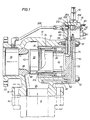
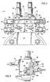
- A manifold assembly (10) for controlling actuation of a safety relief valve (12) the safety relief valve (12) including a safety relief valve housing (13) having an upstream relief valve inlet port (24) and a downstream relief valve outlet port (26), a relief valve member (32) moveable within the relief valve housing (13) for controlling actuation of the safety relief valve (12), and a dome chamber (44) within the relief valve housing (13) normally maintained at substantially inlet pressure for acting on the relief valve member (32) to maintain the safety relief valve (12) closed, the manifold assembly (10) comprising:a manifold block (60) having a block inlet port (230) in fluid communication with the valve inlet, a block dome pressure port (232) in fluid communication with the dome chamber (44) in safety relief valve housing (13), and a first test port (234);a first control cavity (220) in the manifold block (60), the first control cavity (220) including a first inlet port (248) and a first dome pressure port (270);a first inlet passageway (244) in the manifold block (60) fluidly connecting the block inlet port (230) and the first inlet port (248);a first inlet control valve (74) mounted on the manifold block (60) for selectively closing off the first inlet passageway (244) within the manifold block (60);a first dome pressure passageway (262) in the manifold block (60) fluidly connecting the block dome pressure port (232) and the first dome pressure port (270);a first dome pressure control valve (76) mounted on the manifold block (60) for selectively closing off the first dome pressure passageway (262) within the manifold block (60);a first vent passageway (282) for venting fluid pressure from the first control cavity (220);a first pilot valve (70) responsive to pressure in the first inlet port (248), the first pilot valve (70) being normally closed for maintaining fluid communication between the first inlet port (248) and the first dome pressure port (232) for supplying pressure to the dome chamber (44) in the relief valve housing (13) and for prohibiting fluid communication between the first dome pressure port (232) and the first vent passageway (282), and the first pilot valve (70) opening to establish fluid communication between the first dome pressure port (270) and the first vent passageway (282) to relieve pressure from the dome chamber (44) in the safety relief valve to open the safety relief valve (12) when the pressure reaches a selected value;a second control cavity (222) in the manifold block (60), the second control cavity (222) including a second inlet port (250) and a second dome pressure port (272);a second inlet passageway (246) in the manifold block (60) fluidly connecting the block inlet port (230) and the second inlet port (250);a second inlet control valve (84) mounted on the manifold block (60) for selectively closing off the second inlet passageway (246) within the manifold block (60);a second dome pressure passageway (264) in the manifold block (60) fluidly connecting the block dome pressure port (232) and the second dome pressure port (272);a second dome pressure control valve (86) mounted on the manifold block (60) for selectively closing off the second dome pressure passageway (264) within the manifold block (60);a second vent passageway (284) for venting fluid pressure from the second control cavity (222);and a selector mechanism (89) for mechanically preventing closing of the first inlet control valve (74) and the first dome pressure control valve (76) when in a first position, and for mechanically preventing closure of the second inlet control valve (84) and the second dome pressure control valve (86) when in a second position.
- The manifold assembly as defined in claim 1, further comprising:the manifold block (60) has a lower face (62) for mounting engagement with an end plate (56) of the safety relief valve (12); andthe first pilot valve (70) extends through an upper face (63) in the manifold block (60) opposing the lower face (62).
- The manifold assembly as defined in any of claims 1 or 2 further comprising:a first test passageway (274) in the manifold block (60) for fluidly connecting the first test port (234) and the first control cavity (220);a first test control valve (78) mounted on the manifold block for selectively closing off the first test passageway (274).
- The manifold assembly as defined in any of claims 1, 2 or 3 further comprising:a second test port (236) in the manifold block (60);a second test passageway (276) in the manifold block (60) for fluidly connecting the second test port (236) and the second control cavity (222); anda second test control valve (88) mounted on the manifold block for selectively closing off the second test passageway (276) within the manifold block.
- The manifold assembly as defined in any preceding claim, further comprising:a second pilot valve (80) responsive to pressure in the second inlet port (250), the second pilot valve (80) being normally closed for maintaining fluid communication between the second inlet port (250) and the second dome pressure port (272) for supplying fluid pressure to the dome chamber (44) in the relief valve housing (13) and for prohibiting fluid communication between the second dome pressure port (272) and the second vent passageway (284), and the second pilot valve (80) opening to establish fluid communication between the second dome pressure port (272) and the second vent passageway (284) to relieve pressure from the dome chamber (44) in the safety relief valve (12) to open the safety relief valve (12) when the pressure at the upstream relief valve inlet port (24) reaches a selected value.
- The manifold assembly as defined in any preceding claim, further comprising:a dome chamber line (54) for fluidly interconnecting the dome chamber (44) in the relief valve and the downstream relief valve outlet port (26); andan unloader valve (202) mounted at least substantially within the manifold block (60), and the unloader valve (202) including an unloader valve member (204) and an unloader dome chamber (206) normally maintained at substantially vessel pressure, the unloader valve member (204) being normally closed for prohibiting fluid communication between the dome chamber line (54) and the dome chamber (44) in the relief valve, and the unloader valve opening when the first pilot valve (70) opens to release pressure in the dome chamber (44) in the relief valve to the downstream relief valve outlet port (26).
- The manifold assembly as defined in claim 1, wherein the first pilot valve includes a metal pilot valve member and a metal seat, the metal pilot valve member and metal seat cooperating for sealing pressure in the first control cavity.
- The manifold assembly as defined in any preceding claim, wherein the first pilot valve (70) is mounted at least partially within the first control cavity (220) for controlling fluid pressure within the manifold block (60) between the first inlet port (248) and the first dome pressure port (270).
- The manifold assembly as defined in claim 1, further comprising:an auxiliary control member mounted at least partially within the second control cavity.
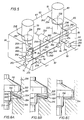
- The manifold assembly as defined in claim 1, wherein the pilot valve comprises:a cartridge valve (80) assembly for mounting within a block cavity extending through a face (62) in a block (60), the block cavity (116) having a central valve axis, the block (60) having a first passageway (254) therein communicating with a first portion (114) of the block cavity (116), and a second passageway (268) therein communicating with a second portion (120) of the block cavity (116) axially spaced from the first portion (114) of the block cavity, the cartridge valve assembly comprising:a valve body (110) positioned within the cavity (116) and having a valve seat therein;a valve element (159) carried by the valve body (110) and moveable with respect thereto for sealing engagement with the valve seat (154) to fluidly isolate the first passageway (254) and the second passageway (260), and for unsealing with the seat (154) to establish fluid communication between the first passageway (254) and the second passageway (268);a seal carried by the valve body for sealing engagement between the valve body and the block at a location axially between the first portion of the block cavity and the second portion of the block cavity; anda bushing (126) having a stop for engagement with the valve body (110) and external threads (132) for threaded engagement with the manifold block (60).
- The manifold assembly as defined in claim 10, wherein the seal further comprises:a metal washer (122, 320) for sealing engagement between the valve body (110) and the manifold block (60) and the metal washer (122, 320) having a frustoconical upper surface and a frustoconical lower surface prior to being compressed into sealing engagement between the valve body (110) and the manifold block (60), and the metal washer (122, 320) having an upper knife edge (330) for sealing engagement with an outer cylindrical surface (332) of the valve body (110) and a lower knife edge (324) for sealing engagement with an inner cylindrical surface (336) of the manifold block (60).
- The manifold assembly as defined in claim 11, wherein a radially inner surface (326) of the metal washer (320) and a radially outer surface (328) of the metal washer (320) are each inclined at an angle of from about 8 ° to about 15 ° with respect to centerline of the valve body (110) when the upper knife edge and the lower knife edge initially engage the outer cylindrical surface of the valve body and the inner cylindrical surface of the manifold block cavity, respectively.
- The manifold assembly as defined in claim 10, further comprising:a biasing member (138) for exerting a biasing force on the valve element (159) to bias the valve element (159) toward engagement with the seat (154); anda valve pressure setting mechanism (144, 146) carried by the valve body (110) for adjusting the biasing force exerted on the valve element.
- The manifold assembly as defined in claim 10, wherein each of the valve element (159) and the seat are formed from metal (154) for sealing high temperature fluids.
- The manifold assembly as defined in claim 10, further comprising:a manifold block cavity (116) having a third passageway therein communicating with a third portion (120) of the block cavity (116) axially spaced opposite the second portion (124) of a manifold block cavity (116) with respect to the first portion (114) of the manifold block cavity;a blowdown seat (168) carried by the valve body (110); anda blowdown element (164) for sealing engagement with the blowdown seat (168) to fluidly isolate the first passageway (254) and the third passageway when the first and second passageways (254, 268) are in fluid communication, and for unsealing with the blowdown seat (168) to maintain fluid communication between the first passageway (254) and the third passageway when fluid pressure between the first and second passageways (254, 268) is blocked by sealing engagement between the valve element (159) and the valve seat (154).
- The manifold assembly as defined in claim 15, further comprising:another seal (118) carried by the valve body (110) for substantial sealing engagement between the valve body (110) and the manifold block (60) at a location between the first portion (114) of the block cavity (116) and the third portion (120) of the block cavity (116).
- The manifold assembly as defined in claim 16, further comprising:a blowdown pressure setting mechanism (166, 170) carried by the valve body (110) for adjusting the blowdown pressure to reseal the blowdown element (164) with the blowdown seat (168).
Priority Applications (1)
| Application Number | Priority Date | Filing Date | Title |
|---|---|---|---|
| EP03001630A EP1306596B1 (en) | 1995-09-01 | 1996-08-15 | Dual pilot manifold assembly for a safety relief valve |
Applications Claiming Priority (3)
| Application Number | Priority Date | Filing Date | Title |
|---|---|---|---|
| US523051 | 1995-09-01 | ||
| US08/523,051 US5590684A (en) | 1995-09-01 | 1995-09-01 | Dual pilot manifold assembly for a safety relief valve |
| PCT/US1996/013253 WO1997009553A1 (en) | 1995-09-01 | 1996-08-15 | Dual pilot manifold assembly for a safety relief valve |
Related Child Applications (1)
| Application Number | Title | Priority Date | Filing Date |
|---|---|---|---|
| EP03001630A Division EP1306596B1 (en) | 1995-09-01 | 1996-08-15 | Dual pilot manifold assembly for a safety relief valve |
Publications (3)
| Publication Number | Publication Date |
|---|---|
| EP0842376A1 EP0842376A1 (en) | 1998-05-20 |
| EP0842376A4 EP0842376A4 (en) | 1999-01-07 |
| EP0842376B1 true EP0842376B1 (en) | 2003-04-23 |
Family
ID=24083474
Family Applications (2)
| Application Number | Title | Priority Date | Filing Date |
|---|---|---|---|
| EP96928880A Expired - Lifetime EP0842376B1 (en) | 1995-09-01 | 1996-08-15 | Dual pilot manifold assembly for a safety relief valve |
| EP03001630A Expired - Lifetime EP1306596B1 (en) | 1995-09-01 | 1996-08-15 | Dual pilot manifold assembly for a safety relief valve |
Family Applications After (1)
| Application Number | Title | Priority Date | Filing Date |
|---|---|---|---|
| EP03001630A Expired - Lifetime EP1306596B1 (en) | 1995-09-01 | 1996-08-15 | Dual pilot manifold assembly for a safety relief valve |
Country Status (7)
| Country | Link |
|---|---|
| US (2) | US5590684A (en) |
| EP (2) | EP0842376B1 (en) |
| AU (1) | AU6847396A (en) |
| DE (2) | DE69627666T2 (en) |
| IN (1) | IN190201B (en) |
| NO (1) | NO315339B1 (en) |
| WO (1) | WO1997009553A1 (en) |
Families Citing this family (26)
| Publication number | Priority date | Publication date | Assignee | Title |
|---|---|---|---|---|
| DE19816463C1 (en) | 1998-04-14 | 1999-06-02 | Siemens Ag | Controller for safety valves in primary circuits of PWRs |
| US5950657A (en) * | 1998-05-12 | 1999-09-14 | Teledyne Industries, Inc. | Modulating action non-flowing pilot operated relief valve |
| US6209577B1 (en) | 1998-05-12 | 2001-04-03 | Curtiss-Wright Flow Control Corporation | Modulating action non-flowing pilot operated relief valve |
| US6220280B1 (en) | 1999-05-12 | 2001-04-24 | Curtis-Wright Flow Control Corporation | Pilot operated relief valve with system isolating pilot valve from process media |
| US6240943B1 (en) * | 1999-05-18 | 2001-06-05 | Loren C. Smith | Method and apparatus for maintaining a constant ratio of gases in a mixture subject to steady state and intermittent flow conditions |
| US6161570A (en) * | 1999-06-01 | 2000-12-19 | Tyco Flow Control, Inc. | Pilot-operated relief valve |
| US6386227B1 (en) * | 1999-09-14 | 2002-05-14 | Flow Safe, Inc. | Non-flowing pilot valve |
| US6318406B1 (en) | 2000-03-14 | 2001-11-20 | Tyco Flow Control, Inc. | Pilot operated relief valve |
| GB2384327B (en) * | 2001-11-12 | 2005-06-22 | Otto Harman Seyfarth | Integrated Pneumatic manifold |
| US6805155B2 (en) | 2001-11-16 | 2004-10-19 | Hydraforce, Inc. | Cartridge relief valve with improved stability |
| US6769880B1 (en) | 2002-09-19 | 2004-08-03 | Mangonel Corporation | Pressure blowdown system for oil injected rotary screw air compressor |
| US7044011B2 (en) * | 2003-04-30 | 2006-05-16 | Honeywell International, Inc. | Test fixture assembly for directional pilot valve and related method |
| US7413612B2 (en) * | 2003-07-10 | 2008-08-19 | Applied Materials, Inc. | In situ substrate holder leveling method and apparatus |
| US20060129087A1 (en) * | 2004-03-31 | 2006-06-15 | Takefumi Uesugi | Method and apparatus for supplying predetermined gas into body cavities of a patient |
| JP4573556B2 (en) * | 2004-03-31 | 2010-11-04 | オリンパス株式会社 | Air supply device |
| US7572340B2 (en) * | 2004-11-29 | 2009-08-11 | Applied Materials, Inc. | High resolution substrate holder leveling device and method |
| DE202006011073U1 (en) * | 2006-07-18 | 2007-12-06 | Erben Kammerer Kg | Shut-off |
| US20080196773A1 (en) * | 2007-02-16 | 2008-08-21 | Honeywell International, Inc. | Ventline control valve assembly |
| JP4768855B2 (en) * | 2007-06-18 | 2011-09-07 | 株式会社東芝 | Safety valve drive system |
| CN101608644B (en) * | 2009-03-06 | 2014-02-12 | 上海人豪液压技术有限公司 | Combination hydraulic integrated control valve block system |
| US9915373B2 (en) * | 2011-07-08 | 2018-03-13 | Fmc Technologies, Inc. | Electronically controlled pressure relief valve |
| CN103711961B (en) * | 2012-09-28 | 2017-11-17 | 艾默生过程管理调节技术公司 | Type pilot relief valve with dual boot adjuster |
| MX365988B (en) * | 2013-08-06 | 2019-05-30 | Arturo Flores Leija Hugo | Opening and closing system for pressurised fluids. |
| DE102014219740A1 (en) * | 2014-09-30 | 2016-03-31 | Robert Bosch Gmbh | Pilot operated pressure relief valve with side pressure connection |
| CN113340513B (en) * | 2021-07-01 | 2022-12-06 | 鲍亮 | Pressure gauge |
| US11873921B2 (en) * | 2021-08-10 | 2024-01-16 | Electric Power Research Institute, Inc. | Servo-controlled metering valve and fluid injection system |
Family Cites Families (26)
| Publication number | Priority date | Publication date | Assignee | Title |
|---|---|---|---|---|
| US2731032A (en) * | 1952-08-07 | 1956-01-17 | Reynolds Gas Regulator Company | Fluid pressure regulating system |
| US2754840A (en) * | 1953-01-29 | 1956-07-17 | Hannifin Corp | Valves |
| US2884008A (en) * | 1956-04-29 | 1959-04-28 | British Oxygen Co Ltd | Valve interlock means |
| US3512560A (en) * | 1968-02-19 | 1970-05-19 | Anderson Greenwood & Co | Relief valve |
| US3664362A (en) * | 1969-02-06 | 1972-05-23 | Anderson Greenwood & Co | Pilot valve |
| DE1966461C3 (en) * | 1969-02-06 | 1981-06-04 | Anderson, Greenwood & Co., Houston, Tex. | Pilot valve for a pressure relief valve |
| US4005728A (en) * | 1975-08-29 | 1977-02-01 | Globe Valve Corporation | Faucet valve |
| CA1034488A (en) * | 1975-09-10 | 1978-07-11 | Mcevoy Oilfield Equipment Co. | Seal |
| US4172466A (en) * | 1977-07-01 | 1979-10-30 | Target Rock Corporation | Self-actuated pilot-controlled safety valve |
| US4402341A (en) * | 1981-02-13 | 1983-09-06 | Vapor Corporation | Pilot operated relief valve |
| US4384590A (en) * | 1981-06-03 | 1983-05-24 | Crosby Valve & Gage Company | Pressure responsive pilot valve |
| US4429711A (en) * | 1982-03-08 | 1984-02-07 | Anderson, Greenwood & Co. | Multivalve manifold interlock and control system |
| US4527770A (en) * | 1982-08-12 | 1985-07-09 | Axelson, Inc. | In-service test valve |
| US4615356A (en) * | 1983-09-22 | 1986-10-07 | Vapor Corporation | Modulating pressure operated pilot relief valve |
| US4731914A (en) * | 1984-01-06 | 1988-03-22 | Zeuner Kenneth W | Method for manufacturing an electrohydraulic valve assembly |
| DE3408012A1 (en) * | 1984-03-05 | 1985-09-05 | Gerhard Dipl.-Ing. Warren Mich. Mesenich | ELECTROMAGNETIC INJECTION VALVE |
| DE3414294A1 (en) * | 1984-04-14 | 1985-10-24 | Drago Dipl.-Ing. 5020 Frechen Kober | SAFETY VALVE FOR LIQUID GAS TANKS, ESPECIALLY SHIP TANKS |
| US4821772A (en) * | 1984-11-02 | 1989-04-18 | Anderson Greenwood & Co. | Dual active selector valve |
| US4672995A (en) * | 1984-12-28 | 1987-06-16 | Anderson-Greenwood Usa, Inc. | Redundant pilot valve control system |
| US4679584A (en) * | 1986-08-11 | 1987-07-14 | Dresser Industries, Inc. | Soft seat Y-pattern check valve |
| US4870989A (en) * | 1988-06-20 | 1989-10-03 | Keystone International, Inc. | High temperature safety relief system |
| US4848397A (en) * | 1988-06-20 | 1989-07-18 | Keystone International, Inc. | High temperature safety relief system |
| US4865074A (en) * | 1988-06-20 | 1989-09-12 | Keystone International Inc. | High temperature safety relief system |
| DE8809436U1 (en) * | 1988-07-23 | 1988-09-08 | Festo Kg, 7300 Esslingen, De | |
| US4936339A (en) * | 1989-07-14 | 1990-06-26 | Bennett Barry D | Cartridge-type check valve |
| US5011116A (en) * | 1990-03-30 | 1991-04-30 | Keystone International Holdings Corp. | Shock absorbing sealing means for flow control devices |
-
1995
- 1995-09-01 US US08/523,051 patent/US5590684A/en not_active Expired - Lifetime
-
1996
- 1996-08-12 IN IN1444CA1996 patent/IN190201B/en unknown
- 1996-08-15 EP EP96928880A patent/EP0842376B1/en not_active Expired - Lifetime
- 1996-08-15 DE DE69627666T patent/DE69627666T2/en not_active Expired - Lifetime
- 1996-08-15 EP EP03001630A patent/EP1306596B1/en not_active Expired - Lifetime
- 1996-08-15 DE DE69637897T patent/DE69637897D1/en not_active Expired - Lifetime
- 1996-08-15 AU AU68473/96A patent/AU6847396A/en not_active Abandoned
- 1996-08-15 WO PCT/US1996/013253 patent/WO1997009553A1/en active IP Right Grant
- 1996-11-06 US US08/743,724 patent/US5769113A/en not_active Expired - Lifetime
-
1998
- 1998-02-25 NO NO19980787A patent/NO315339B1/en not_active IP Right Cessation
Also Published As
| Publication number | Publication date |
|---|---|
| AU6847396A (en) | 1997-03-27 |
| DE69627666D1 (en) | 2003-05-28 |
| EP0842376A1 (en) | 1998-05-20 |
| NO980787L (en) | 1998-04-28 |
| US5769113A (en) | 1998-06-23 |
| IN190201B (en) | 2003-06-28 |
| DE69637897D1 (en) | 2009-05-20 |
| EP1306596A3 (en) | 2004-10-27 |
| EP1306596B1 (en) | 2009-04-08 |
| WO1997009553A1 (en) | 1997-03-13 |
| NO980787D0 (en) | 1998-02-25 |
| US5590684A (en) | 1997-01-07 |
| EP1306596A2 (en) | 2003-05-02 |
| NO315339B1 (en) | 2003-08-18 |
| DE69627666T2 (en) | 2004-02-05 |
| EP0842376A4 (en) | 1999-01-07 |
Similar Documents
| Publication | Publication Date | Title |
|---|---|---|
| EP0842376B1 (en) | Dual pilot manifold assembly for a safety relief valve | |
| US6015134A (en) | Pneumatic actuator assembly | |
| US6250605B1 (en) | Valve actuator apparatus | |
| US5624101A (en) | Dual seal valve | |
| US4230299A (en) | Pressure balanced gate valve having selective actuator systems | |
| EP0216439B1 (en) | Non-flowing modulating pilot operated relief valve | |
| EP0468621B1 (en) | Pilot valve for control valves and method of operation | |
| KR0165882B1 (en) | Shutoff and regulating valve | |
| US4274432A (en) | Valve | |
| US6161570A (en) | Pilot-operated relief valve | |
| US4364541A (en) | Isolating device for calibrated safety valve | |
| CN113195963B (en) | Device for filling and extracting gas | |
| US4548067A (en) | Method and apparatus for testing a relief valve | |
| USRE29322E (en) | Valve and actuator assembly | |
| US4860784A (en) | Non-rising stem valve assembly and method of replacing a permanent seal | |
| US4840057A (en) | Method and apparatus for testing relief valve | |
| JP2007139010A (en) | Ball valve | |
| US5501242A (en) | Pressure relief valve | |
| CA2230480C (en) | Dual pilot manifold assembly for a safety relief valve | |
| US4852387A (en) | Method for testing relief valve | |
| US5350222A (en) | Auxiliary stabilizer valve for VX vent valve | |
| CA2547602C (en) | Dual pilot manifold assembly for a safety relief valve | |
| US11215323B2 (en) | Pressure regulator with inbuilt safety valve to relieve pressure in the event of an overpressure downstream | |
| JP4018208B2 (en) | Pilot operated relief valve | |
| USRE33928E (en) | Fire-safe valve actuator |
Legal Events
| Date | Code | Title | Description |
|---|---|---|---|
| PUAI | Public reference made under article 153(3) epc to a published international application that has entered the european phase |
Free format text: ORIGINAL CODE: 0009012 |
|
| 17P | Request for examination filed |
Effective date: 19980311 |
|
| AK | Designated contracting states |
Kind code of ref document: A1 Designated state(s): DE FR GB IT |
|
| A4 | Supplementary search report drawn up and despatched | ||
| AK | Designated contracting states |
Kind code of ref document: A4 Designated state(s): DE FR GB IT |
|
| 17Q | First examination report despatched |
Effective date: 20020124 |
|
| GRAH | Despatch of communication of intention to grant a patent |
Free format text: ORIGINAL CODE: EPIDOS IGRA |
|
| GRAH | Despatch of communication of intention to grant a patent |
Free format text: ORIGINAL CODE: EPIDOS IGRA |
|
| GRAA | (expected) grant |
Free format text: ORIGINAL CODE: 0009210 |
|
| AK | Designated contracting states |
Designated state(s): DE FR GB IT |
|
| REG | Reference to a national code |
Ref country code: GB Ref legal event code: FG4D |
|
| REF | Corresponds to: |
Ref document number: 69627666 Country of ref document: DE Date of ref document: 20030528 Kind code of ref document: P |
|
| ET | Fr: translation filed | ||
| PLBE | No opposition filed within time limit |
Free format text: ORIGINAL CODE: 0009261 |
|
| STAA | Information on the status of an ep patent application or granted ep patent |
Free format text: STATUS: NO OPPOSITION FILED WITHIN TIME LIMIT |
|
| 26N | No opposition filed |
Effective date: 20040126 |
|
| REG | Reference to a national code |
Ref country code: GB Ref legal event code: 732E |
|
| REG | Reference to a national code |
Ref country code: FR Ref legal event code: TP Ref country code: FR Ref legal event code: CD Ref country code: FR Ref legal event code: CA |
|
| PGFP | Annual fee paid to national office [announced via postgrant information from national office to epo] |
Ref country code: FR Payment date: 20141017 Year of fee payment: 19 Ref country code: DE Payment date: 20141029 Year of fee payment: 19 Ref country code: GB Payment date: 20141027 Year of fee payment: 19 |
|
| PGFP | Annual fee paid to national office [announced via postgrant information from national office to epo] |
Ref country code: IT Payment date: 20141028 Year of fee payment: 19 |
|
| REG | Reference to a national code |
Ref country code: DE Ref legal event code: R119 Ref document number: 69627666 Country of ref document: DE |
|
| GBPC | Gb: european patent ceased through non-payment of renewal fee |
Effective date: 20150815 |
|
| PG25 | Lapsed in a contracting state [announced via postgrant information from national office to epo] |
Ref country code: IT Free format text: LAPSE BECAUSE OF NON-PAYMENT OF DUE FEES Effective date: 20150815 |
|
| REG | Reference to a national code |
Ref country code: FR Ref legal event code: ST Effective date: 20160429 |
|
| PG25 | Lapsed in a contracting state [announced via postgrant information from national office to epo] |
Ref country code: DE Free format text: LAPSE BECAUSE OF NON-PAYMENT OF DUE FEES Effective date: 20160301 Ref country code: GB Free format text: LAPSE BECAUSE OF NON-PAYMENT OF DUE FEES Effective date: 20150815 |
|
| PG25 | Lapsed in a contracting state [announced via postgrant information from national office to epo] |
Ref country code: FR Free format text: LAPSE BECAUSE OF NON-PAYMENT OF DUE FEES Effective date: 20150831 |