EP0841574A2 - Integriertes Motor- und Diagnosegerät und dessen Betriebsverfahren - Google Patents
Integriertes Motor- und Diagnosegerät und dessen Betriebsverfahren Download PDFInfo
- Publication number
- EP0841574A2 EP0841574A2 EP97119524A EP97119524A EP0841574A2 EP 0841574 A2 EP0841574 A2 EP 0841574A2 EP 97119524 A EP97119524 A EP 97119524A EP 97119524 A EP97119524 A EP 97119524A EP 0841574 A2 EP0841574 A2 EP 0841574A2
- Authority
- EP
- European Patent Office
- Prior art keywords
- motor
- diagnostic apparatus
- diagnostic
- signal
- sensors
- Prior art date
- Legal status (The legal status is an assumption and is not a legal conclusion. Google has not performed a legal analysis and makes no representation as to the accuracy of the status listed.)
- Granted
Links
- 238000000034 method Methods 0.000 title abstract description 19
- 238000012545 processing Methods 0.000 claims abstract description 16
- 230000002159 abnormal effect Effects 0.000 claims abstract description 9
- 230000004907 flux Effects 0.000 claims description 17
- 230000005540 biological transmission Effects 0.000 claims 1
- 238000005070 sampling Methods 0.000 claims 1
- 238000012423 maintenance Methods 0.000 abstract description 7
- 238000012544 monitoring process Methods 0.000 abstract description 5
- 230000000694 effects Effects 0.000 abstract description 3
- 238000004891 communication Methods 0.000 description 18
- 230000006870 function Effects 0.000 description 6
- 238000004458 analytical method Methods 0.000 description 4
- 230000015556 catabolic process Effects 0.000 description 4
- 230000008569 process Effects 0.000 description 4
- 238000004804 winding Methods 0.000 description 4
- 238000006731 degradation reaction Methods 0.000 description 3
- 238000003745 diagnosis Methods 0.000 description 3
- 238000010586 diagram Methods 0.000 description 3
- 230000006698 induction Effects 0.000 description 3
- 238000004422 calculation algorithm Methods 0.000 description 2
- 238000004364 calculation method Methods 0.000 description 2
- 238000007635 classification algorithm Methods 0.000 description 2
- 230000001143 conditioned effect Effects 0.000 description 2
- 230000003750 conditioning effect Effects 0.000 description 2
- 238000012774 diagnostic algorithm Methods 0.000 description 2
- 238000002405 diagnostic procedure Methods 0.000 description 2
- 238000012986 modification Methods 0.000 description 2
- 230000004048 modification Effects 0.000 description 2
- 239000004593 Epoxy Substances 0.000 description 1
- 230000009471 action Effects 0.000 description 1
- 230000004323 axial length Effects 0.000 description 1
- 230000008901 benefit Effects 0.000 description 1
- 238000013145 classification model Methods 0.000 description 1
- 238000005553 drilling Methods 0.000 description 1
- 238000010292 electrical insulation Methods 0.000 description 1
- 238000001914 filtration Methods 0.000 description 1
- 230000036541 health Effects 0.000 description 1
- 238000009413 insulation Methods 0.000 description 1
- WABPQHHGFIMREM-UHFFFAOYSA-N lead(0) Chemical compound [Pb] WABPQHHGFIMREM-UHFFFAOYSA-N 0.000 description 1
- 239000004973 liquid crystal related substance Substances 0.000 description 1
- 238000004519 manufacturing process Methods 0.000 description 1
- 239000000463 material Substances 0.000 description 1
- 230000007246 mechanism Effects 0.000 description 1
- 238000003909 pattern recognition Methods 0.000 description 1
- 239000011800 void material Substances 0.000 description 1
Images


Classifications
-
- G—PHYSICS
- G01—MEASURING; TESTING
- G01R—MEASURING ELECTRIC VARIABLES; MEASURING MAGNETIC VARIABLES
- G01R31/00—Arrangements for testing electric properties; Arrangements for locating electric faults; Arrangements for electrical testing characterised by what is being tested not provided for elsewhere
- G01R31/34—Testing dynamo-electric machines
- G01R31/343—Testing dynamo-electric machines in operation
Definitions
- the present invention relates to diagnostic apparatus and techniques for diagnosing and predicting failure in industrial machinery and, more particularly, to methods and apparatus for diagnosing the condition of rotating electrical and other machinery such as motors, generators, and gears wherein the diagnostics are integrated within the motor, generator, gear or other device.
- U.S. Patent No. 5,488,281 to Unsworth, et al. teaches a method and apparatus for predicting motor winding failure using zero crossing times.
- a motor controller is utilized which provides stator winding currents at a frequency of X cycles per second whereby the zero crossing times may be controlled and observed.
- the control system of the Unsworth, et al. apparatus alters the RMS supply line current by controlling the period of a notch introduced into the supply voltage each time the associated line current becomes zero.
- a thyristor pair disposed in series with the motor lead wires operate as an open circuit.
- an internally generated motor back EMF voltage may be observed by the controller.
- active motor control must be interrupted in order to detect and predict motor winding failures. Further, while the active motor control is interrupted, additional active inputs or signals must be introduced into the motor control circuit in order to induce the creation of observable motor parameters necessary to predict or conclude motor winding failures.
- the present invention overcomes many of the problems of the present conventional monitoring apparatus and techniques by providing a method and apparatus well suited for diagnosing motor conditions in the field while the motor is in use in production or the like.
- the present apparatus provides an integrated motor and motor diagnostic tool capable of passive observation of the operating parameters in an unobtrusive manner and thus without interference to the process to which the motor is connected. Further, the present invention provides the capability of alerting an operator of various motor fault conditions as they occur and, in addition, to alerting the operator of less serious cautions regarding the operation of the motor as well.
- the present invention includes a diagnostic method and apparatus ideally suited for use with an electric motor of the type having a rotor, a stator, at least one bearing supporting the rotor, and a plurality of motor lead wires carrying electric current to the motor.
- Other applications are contemplated as well including electric generators, gear boxes, and in systems including "embedded motors" such as in consumer appliances or the like.
- the diagnostic apparatus includes at least one sensor in the motor for measuring a first physical condition of the motor and generating a first physical condition signal based on the measured first physical condition.
- a processing unit in the diagnostic apparatus is connected to the at least one sensor for determining the first operating condition of the motor based on the first physical condition signal.
- the processing unit generates an abnormal motor operation signal when the determined first operating condition is in a predetermined range.
- a signal communicating unit is responsive to the abnormal motor operation signal from the processing unit and communicates a motor diagnostic signal from the diagnostic apparatus to another device, a human, or any other supervisory control via a display unit or by wireless alphanumeric paging techniques.
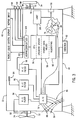
- the present invention will be described in the context of the exemplary integrated motor and diagnostic system 10 shown in FIGURE 1.
- the integrated motor and diagnostic system 10 generally includes a motor and diagnostic unit 12, a supervisory computer 14, a central paging system 16, and a remote operator pager 18.
- the motor and diagnostic unit 12 is preferably connected to the supervisory computer 14 through a communication link 20.
- the supervisory computer 14 is connected to the central paging system 16 through a commercial communication link 22.
- the central paging system 16 generally includes a local switchboard 24 and a remote broadcast tower 26 for generating an RF communication link signal 28 for delivery of alphanumeric messages or other signals or information from the supervisory computer 14 through the commercial communication link 22 and in turn to the remote operator pager 18. In that manner, an operator may be alerted to the condition of the motor and diagnostic unit 12 from a remote location.
- the motor and diagnostic unit includes an electric motor 30 having an output shaft 32 connected to a load 34.
- the electric motor 30 receives power from a remote power source (not shown) through a set of power lead wires 36.
- the motor and diagnostic unit 12 includes a diagnostic apparatus 40 integrated into the electric motor 30.
- the diagnostic apparatus 40 provides an operator with a display device 42 for visually displaying various operating conditions of the motor 30.
- the diagnostic apparatus 40 includes a set of discrete motor condition display indicia including a fault indicia 44, a caution indicia 46 and a normal operation indicia 48.
- the motor and diagnostic unit 12 includes a communication port 50 for interfacing the diagnostic apparatus 40 with the supervisory computer 14 via the communication link 20.
- the link 20 preferably adheres to the RS232C standard for communicating command and parameter information.
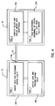
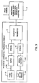
- FIGURE 2 shows a function block schematic representation of the system illustrated in FIGURE 1 including the motor and diagnostic unit 12 connected to the load 34 through the output shaft 32 comprising the electric motor 30.
- the diagnostic apparatus 40 is connected to the supervisory computer 14 via a communication link 20 through the communication port 50 provided in the diagnostic apparatus 40.
- the supervisory computer 14 is connected to the central paging system 16 through a commercial communication link 22.
- the supervisory computer 14 includes an internal modem whereby communication with the central paging system 16 is via standard commercial telephone system using standard dial-up techniques.
- the alphanumeric pager 18 is illustrated.
- the diagnostic apparatus 40 includes a plurality of functional subsystems including a signal communicating unit 54 having a pair of subsystems namely, the communication port 50 described above and, in addition, a man machine interface 52, commonly referred to in the art as an "MMI".
- the communication port 50 and the man machine interface 52 collectively form the signal communicating unit 54.
- a processor unit 56 executes various diagnostic algorithms stored in an algorithm memory 60 and performs various diagnostic calculations utilizing a data memory 54.
- An interface to the motor power lead wires 36 is provided by a motor power connection interface 62.
- an interface is provided to a plurality of embedded sensors which would be described below through an embedded sensor interface 64.
- power is provided to the processor unit and to other components forming the diagnostic apparatus 40 from a control and sensor power unit 66.
- FIGURE 3 is a schematic representation of the motor and diagnostic unit 12 shown in its preferred application wherein the diagnostic apparatus 40 is integrated within a three phase induction motor 30.
- the induction motor illustrated includes a load bearing 70 on a front end thereof and a fan bearing 72 on the back end thereof.
- the output shaft 32 connects the load 34 to the motor 30.
- the other end of the output shaft connects a fan 74 to the motor 30.
- the fan bearing 72 is on the same end of the motor as is the fan 74.
- the load bearing 70 is on the same end of the motor as is the load 34.
- FIGURE 3 is a cut away sectional view of the motor exposing a stator tooth 76 of the induction motor having an air gap flux sensor 80 connected thereto for purposes described in greater detail immediately below.
- the air gap flux sensor 80 is connected to the processor unit 56 via an analog to digital converter 78.
- the analog to digital converter converts the analog signals generated by the plurality of sensors including the air gap flux sensor 80 into a digital value for ready use by the processor unit 56.
- Other analog sensors connected to the processor unit 56 via the analog to digital converter 78 include a fan bearing temperature sensor 82, a stator temperature sensor 84, a load bearing temperature sensor 86, a set of motor current sensors 88, a set of motor voltage sensors 90, and a vibration sensor 92.
- the fan bearing temperature sensor 82, the stator temperature sensor 84, and the load bearing temperature sensor 86 are each preferably bi-metallic thermocouple-type sensors for generating an analog voltage proportional to the temperature at the thermocouple lead.
- Each of the temperature sensors are preferably embedded into the target apparatus such as by drilling a hole into the stator core for providing a space to lodge the stator temperature sensor 84. After the stator temperature sensor 84 is lodged into the hole provided therefore in the stator, a suitable epoxy material is disposed into the hole to fill the void providing a good mechanical and thermal connection between the stator temperature sensor 84 and the stator core into which the sensor is embedded.
- each of the bearing temperature sensors 82, 86 are preferably embedded into their respective bearing components. Alternatively, the temperature sensors may be mounted into the motor end brackets near the bearing components.
- the thermocouple temperature sensors 82, 84, 86 are connected to the analog to digital converter 78 through the filter devices 94, 96, 98.
- Each of the filters 94, 96, 98 provide a buffer to smooth any transience that might be experienced by the thermocouple temperature sensors.
- the buffer proves an RC time constant large enough to mask high frequency noise on the thermocouple inputs.
- the analog to digital converter 78 includes a set of motor current sensors 88 and a set of motor voltage sensors 90. Each of these sets of sensors are connected directly to the power lead wires 36 connecting the electric motor 30 to a source of power.
- the motor current sensors 88 are arranged as current transformers on each power line to generate a voltage proportional to the current flowing through the respective power lead wire.
- each of the motor voltage sensors 90 preferably includes a voltage division circuit such as a resistor bridge circuit for providing an analog voltage signal to the analog to digital converter 72 which is within the operating range of the converter.
- the voltage conditioned by the divider circuit remains proportional to the incoming power voltage on the power lead wires 36.
- the air gap flux sensor 80 is illustrated as being wrapped around a stator tooth 76 of the stator of the electric motor 30.
- the air gap flux sensor 80 provides a voltage proportional to the flux experienced at the stator tooth.
- One or more stator teeth may be selected to provide inputs along the axial length of the stator of the motor or circumferentially around the stator, or both. In some applications, it may be desirable to arrange multiple flux sensors or, alternatively, to monitor only the peak inputs from the multiple sensors.
- a vibration sensor 92 is mechanically connected to the casing of the motor 30 to provide a voltage signal proportional to the amount of vibration experienced by the motor. As illustrated, the vibration sensor 92 is connected to the motor casings at a central location. However, one or more vibration sensors may be disposed about the various internal and/or external surfaces of the motor to provide one or more vibration signals. The analog signals from the vibration sensors are converted to digital signals by the A/D mechanism 78 for use by the processor unit 56.
- the processor unit 56 executes various diagnostic algorithms from programs stored in an algorithm memory 60. Further, the processor unit 56 utilizes a data memory 58 to perform various calculations and to store variables.
- a universal asynchronous receiver and transmitter 100 commonly referred to in the art as "UART" is connected to the communication port 50 described above.
- the signal communicating unit 54 includes a keypad and display driver unit 102 and LED driver unit 104.
- the keypad/display driver unit 102 provides suitable signal conditioning a logical interface between the processor unit 56 and the display unit 42.
- the display device 42 is a back lit liquid crystal display having a 2x24 character display.
- the LED driver unit 104 provides a suitable logical interface and signal conditioning and the processor unit 56 and the set of display indicia on the diagnostic apparatus 40 including the fault indicia LED 44, the caution indicia LED 46, and the normal operation indicia LED 48.
- Both the motor and diagnostic unit 12 and the supervisory computer 14 execute a respective set of instructions and logical operations in order to effect the motor diagnostic functions according to the present invention.
- the motor and diagnostic unit 12 may be operated independent of the supervisory computer 14 such as when the communication link 20 is disconnected or during other conditions where the supervisory computer 14 is not necessary.
- the supervisory computer is adapted to interface a plurality of motor and diagnostic units with one or more central paging systems.
- a plurality of diagnostic units may be connected to a plurality of supervisory computers which are in turn connected to a plurality of central paging systems.
- the singular case/toplogy will be used to explain the invention.
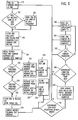
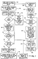
- the motor and diagnostic unit 12 executes a set of logical operations which may generally be grouped into a first task 200 and a second task 202.
- the first task 200 comprises those operations which sample data and determine the health of the electric motor 30.
- the second task 202 comprises those operations which display the collected and computed data and in addition, those tasks which process keypad input and output information.
- An operating system task (not shown) in the motor and diagnostic unit 12 operates generally to call the first task 200 and then, upon a return from task one, the operating system calls task two 202. Thus, the operating system in the motor and diagnostic unit 12 calls the tasks 200, 202 in an alternating fashion.
- the supervisory computer 14 includes an operating system as well (not shown) which includes the basic functions necessary to operate the supervisory computer 14 including a display unit, a keyboard, disk drives and a modem.
- the supervisory computer is PC based and therefore the operating system is preferably one of the commercially available systems such as DOS, Windows, or Windows 95.
- the operating system within the supervisory computer 14 periodically calls task three 204 which generally comprises those operations which compute various parameter values and display motor data on the supervisory computer in a graphical form.
- a fourth task 206 in the supervisory computer 14 is selectively launched by the third task 204 in the supervisory computer 14 when it becomes necessary to page a human operator such as a maintenance engineer with textual information or to send other data indicative of a faulty motor or for other reasons which may require the attention of the human operator.
- the fourth task 206 includes the programming necessary to interface the supervisory computer 14 with the central paging system 16 via a modem or the like in the supervisory computer 14.
- each of the plurality of sensors is polled for their values by the processor unit 56 and the AID converter 78.
- all of the thermocouple sensors are polled as well as the air gap flux sensor and the voltage and current sensors.
- a flag (not shown) in the data memory 58 is inspected to determine whether multiple samples of raw data are required to be polled. In the event that multiple samples of raw data are required as determined by the flag in the memory, a plurality of raw samples are polled by the processor unit and A/D converter in step 214. A second flag in the data memory 58 is inspected to determine whether 256 or 512 samples are taken. In either case, the multiple raw sample data is polled at 1 KHZ into the data memory 58.
- the first task 200 immediately transfers control to step 216 whereat the plurality of sensor value data obtained at step 212 is first filtered through the RC filters 94, 96, 98 or through software means and then manipulated in order to calculate root mean squared RMS values for motor vibration, motor voltage, motor current and flux parameter values.
- the RMS values are for the various motor parameters including vibration, voltage, current and flux values are determined according to well known techniques. The RMS values for each of the parameters are stored in the data memory 58 of the motor and diagnostic unit 12.
- the previously stored threshold values include ranges for motor fault conditions, a range for a motor caution condition, and a range for a normal operating condition.
- Each of the vibration, voltage, current and flux parameters are assigned a range of fault, caution, and normal operation threshold values in the data memory 58 such as through the keypad and display device 42 in a manner described below.
- step 220 the calculated RMS values for vibration, voltage, current and flux parameters are compared against the previously stored fault threshold values for same. If any of the calculated RMS parameters exceed their respective fault threshold values, a message text is retrieved in step 222 from the data memory 58 and in turn displayed on the input and display device 42. As an added precaution and in order to announce the fault condition in a more apparent manner, the fault indicia LED 44 is illuminated in step 224. If only a single parameter indicates a motor fault, the task may selectively monitor only that particular faulty parameter ignoring the other raw data sensor inputs. A benefit is that a greater level of resolution is obtainable.
- step 226 the calculated RMS values for vibration, voltage, current and flux parameters are compared against previously stored caution threshold values. If any of the calculated RMS values for vibration, voltage, current or flux exceed the previously determined caution threshold values, a textual message is retrieved from the data memory 58 and the retrieved message as well as the calculated RMS value exceeding the caution is displayed on the input and display device 42. As with the fault condition, in order to more emphatically emphasize the caution condition, the caution indicia LED 46 is illuminated in step 230.
- each of the fault and caution indicia LEDs 44, 46 are cleared in step 232. In that event, the normal operation indicia LED 48 is illuminated. Further, in the event that no faults or caution conditions are found to exist, a motor running message is displayed on the input and display device 42 at step 234.
- the first task 200 determines at step 236 whether the supervisory computer 14 is connected to the motor and diagnostic unit 12 via the communication link 20 at step 236. If it is determined that the supervisory computer is connected to the motor and diagnostic unit and further that the supervisory computer is requesting one or more sensor parameter values at step 236, the motor and diagnostic unit 12 transmits the requested sensor value data to the supervisory computer at step 238. In that event, the motor and diagnostic unit transmits the calculated RMS values for vibration, voltage, current and flux parameters as well as the status of the fault, caution, and normal operation indicia LEDs.
- step 240 the first task 200 determines whether the supervisory computer 14 has lodged a request for the raw data collected at step 212. If such a request has been lodged, it is determined in step 242 whether 256 samples are requested. If the smaller sample collection is requested, it is transmitted to the supervisory computer at step 244. However, in the event that the larger data set is requested, the raw sample data is transmitted from the data memory 58 of the motor and diagnostic unit to the supervisory computer at step 246.
- the operating system within the motor and diagnostic unit alternately calls the first task 200 and the second task 202.
- the second task 202 shown in FIGURE 6 is then executed by the motor and diagnostic unit.
- the motor and diagnostic unit determines in step 250 whether the status of the keypad input on the input and display device has changed since the previous execution of the second task. In the event that the status has changed, it is determined in step 252 whether any of the fault or caution threshold values stored in the data memory 58 are to be changed. If not, the requested data is displayed on the input and display device 42 at step 254.
- the new value is read at step 256 and entered into the data memory 58 at step 258.
- operator requested data is displayed on the input and display device 42 and, further, new threshold parameter data is entered into the data memory 58 of the motor and diagnostic unit 12 through the input and display device 42.
- a request code is transmitted to the motor and diagnostic unit at step 300 requesting one or more data types or sets of parameter data from the data memory 58.
- the supervisory computer 14 reads the data from the motor and diagnostic unit transmitted via the communication link 20.
- the data includes motor parameter data and text messages as well as the status of the fault, caution and normal operation indicia LEDs.
- FIGURE 8 illustrates the preferred data types and further, illustrates the preferred data characteristics communicated between the motor and diagnostic unit 12 and the supervisory computer 14.
- step 304 of the third task 204 determines whether a failure or fault condition exists by inspecting the status of the transmitted fault indicia information (red LED item or yellow LED item in FIGURE 8). If a fault condition is determined to be present in step 306, the supervisory computer 14 retrieves a recommendation message in step 308 from a memory location (not shown). The retrieved recommendation message is displayed on a screen connected to the supervisory computer. After displaying the recommendation message on the screen, it is next determined in step 310 whether a remote text paging is requested as determined by a flag (not shown) previously stored in the supervisory computer.
- a pager message is constructed in step 314 primarily from the text received from the motor and diagnostic unit.
- the pager message is transmitted through the operating system of the supervisory computer and by launching the fourth task 206 to transmit the page request to the central paging system 16 via the commercial communication link 22.
- the paging request is executed by the fourth task 206 as a background process.
- the fourth task executing in the background preferably includes intelligence to selectively transmit the fault message to the appropriate personnel. In that regard, serious fault messages may be transmitted to a supervisory maintenance operator.
- step 318 the supervisory computer displays the message intended to be transmitted to the remote operator pager 18 on a screen of the supervisory computer.
- step 306 if it is determined that a fault is not present based upon the data transmitted from the motor and diagnostic unit, the supervisory computer computes at step 320, a phase imbalance vector including phase magnitude and direction, in order to display a polar plot of the phase voltage and current on a display screen of the supervisory computer. If it is determined in step 322 that multiple current samples were not requested from the motor and diagnostic unit, graphical representations of the fault, caution and normal operation indicia LEDs are illuminated on a display screen of the supervisory computer in step 324. Further, in step 326, a textual message as well as the raw parameter data values are displayed on a display screen of the supervisory computer. Lastly, a plot of the temperature, current, and/or voltage values are displayed on the display unit of the supervisory computer in step 328.
- step 322 If, in step 322, it is determined that multiple current samples were requested, additional data is requested from the motor and diagnostic unit in 128 byte segments in step 330. A fast fourier transform FFT is next calculated in step 332. In addition, a complete chaos return map is computed in step 334 using the requested data in 128 byte segments. Lastly, in step 336, one or more of the current waive form, fast fourier transform, and chaos map is displayed on a display unit of the supervisory computer 14.
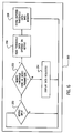
- FIGURE 9 illustrates the present invention in an application extending the diagnosis to include condition-based maintenance of machinery which is system-wide in scope and includes effective condition monitoring and analysis.
- An electric motor 30' receives power from a power system 29 through a set of power lead wires 36'.
- the motor 30' is connected to a load 34' which may be any piece of driven equipment.
- the article of driven equipment or load 34' is in turn connected to other pieces of equipment in a plant and/or process 35.
- a plurality of motor sensors 81 are connected to the motor 30' in a manner described above with respect to the temperatue sensors, the vibration sensor and the current and voltage sensors.
- a plurality of load sensors 83 are connected to the article of driven equipment or load 34'.
- the plurality of motor sensors 81 and the plurality of load sensors 83 are each in turn connected to a diagnostics and prognostics apparatus 13.
- the diagnostics and prognostics apparatus 13 is in turn connected to a higher level maintenance planning or integrated control system 15.
- the diagnostics and prognostics apparatus 13 utilized various analytic techniques such as those which generally fall under the category of current signature analysis which has been shown to detect certain mechanical problems such as bearing failure, rotor problems and electrical insulation breakdown. Powerful filtering and other signal processing and classification algorithms are used by the diagnostic and prognostic apparatus 13 to relate sample sensor information to a plant model for root cause analysis and lifetime prediction. Both qualitative and quantitative motor, driven equipment, and system models are utilized.
- the prognostication performed in the apparatus 13 of the future state of the system is in terms of both physical condition such as stator insulation and estimate of degradation rates and operation impact as a function of degradation. This prognostication no only protects equipment and insures operational readiness, it also allows integrated motor control centers to adjust system usage for optimum machinery system performance or to achieve targeted machinery life.
- the prognostication of system degradation executed in the unit 13 allows maintenance planning to proceed in a efficient manner to provide optimum plant system utilization.
- Several analytical methods are implemented in the unit 13 to accurately perform machinery diagnostics and prognostics.
- the system illustrated in FIGURE 9 includes pattern recognition routines, signal classification algorithms, and models (both qualitative and quantitative) of the machine components and the machinery in its entirety. It is contemplated that all of these techniques and combinations be used in the system described in detail above and shown in FIGS. 1-8.
- the invention provides a method and apparatus for real-time electric motor diagnostics and condition monitoring. While the motor is energized, dynamic operating parameters are determined and a notification signal is generated if predetermined criterion are satisfied.
- the diagnostic apparatus is integrated with the motor and includes a set of sensors, a processing unit, a memory and an output interface for communicating alarms, warnings and calculated operating parameter values or the like to a display device and to an external supervisor having wireless paging capability to alert a remote operator or maintenance personnel.
- the processing unit calculates a general class of derived motor operating parameters such as over-temperature, over-voltage, over-current, excessive vibration, and phase imbalance.
- the processing unit modifies certain data acquisition parameters as necessary to effect an alternative data acquisition strategy which would more likely lead to data dispositive of the condition of the motor.
Landscapes
- Physics & Mathematics (AREA)
- General Physics & Mathematics (AREA)
- Control Of Electric Motors In General (AREA)
- Tests Of Circuit Breakers, Generators, And Electric Motors (AREA)
Applications Claiming Priority (2)
| Application Number | Priority Date | Filing Date | Title |
|---|---|---|---|
| US08/745,167 US5917428A (en) | 1996-11-07 | 1996-11-07 | Integrated motor and diagnostic apparatus and method of operating same |
| US745167 | 2000-12-19 |
Publications (3)
| Publication Number | Publication Date |
|---|---|
| EP0841574A2 true EP0841574A2 (de) | 1998-05-13 |
| EP0841574A3 EP0841574A3 (de) | 1999-07-07 |
| EP0841574B1 EP0841574B1 (de) | 2008-06-11 |
Family
ID=24995534
Family Applications (1)
| Application Number | Title | Priority Date | Filing Date |
|---|---|---|---|
| EP19970119524 Expired - Lifetime EP0841574B1 (de) | 1996-11-07 | 1997-11-07 | Diagnosegerät für einen elektrischen Motor |
Country Status (4)
| Country | Link |
|---|---|
| US (1) | US5917428A (de) |
| EP (1) | EP0841574B1 (de) |
| DE (1) | DE69738758D1 (de) |
| TW (1) | TW371818B (de) |
Cited By (22)
| Publication number | Priority date | Publication date | Assignee | Title |
|---|---|---|---|---|
| GB2338848A (en) * | 1998-06-25 | 1999-12-29 | Csi Technology Inc | Monitoring the history and status of a machine |
| FR2787621A1 (fr) * | 1998-12-18 | 2000-06-23 | Atea | Procede et dispositif d'evaluation des conditions de fonctionnement d'une installation |
| GB2349020A (en) * | 1999-04-17 | 2000-10-18 | Interface Inf Syst Ltd | Monitoring condition of a machine |
| GB2358302A (en) * | 1999-10-12 | 2001-07-18 | Csi Technology Inc | Integrated electric motor operational condition monitor |
| GB2361792A (en) * | 2000-04-25 | 2001-10-31 | Hara Kenneth O | In-line interface box for alarm system |
| EP1218754A4 (de) * | 1999-09-16 | 2004-09-22 | Delphi Tech Inc | Strom-Drehmoment-Vergleich zur Plausibilitäts-untersuchung in einer elektrischenMaschine mit permanet Magneten |
| ES2238155A1 (es) * | 2003-10-07 | 2005-08-16 | Appliances Components Companies Spain, S.A. | Unidad de control para compresor. |
| WO2006048471A1 (es) * | 2004-10-26 | 2006-05-11 | Appliances Components Companies Spain, S.A. | Unidad de control para compresor |
| US7301296B1 (en) * | 2001-07-23 | 2007-11-27 | Rockwell Automation Technologies, Inc. | Integrated control and diagnostics system |
| DE102006032974A1 (de) | 2006-07-17 | 2008-01-31 | Siemens Ag | Elektrische Maschine und elektrischer Antrieb mit einer derartigen elektrischen Maschine |
| EP1298511B2 (de) † | 2001-09-27 | 2009-11-18 | Reliance Electric Technologies, LLC | Integrierte Steuerung und Diagnose für ein motorbetriebenes System unter Verwendung von Schwingungs-, Druck-, Temperatur-, Geschwindigkeits-, und/oder Stromanalyse |
| GB2484960A (en) * | 2010-10-28 | 2012-05-02 | Kevin Kitching | Smart motor disconnection switch |
| EP2515194A3 (de) * | 2007-03-09 | 2013-01-16 | Regal-Beloit Corporation | Verfahren und System zur Aufzeichnung von Betriebsinformationen eines elektronisch kommutierten Motors |
| US8777138B2 (en) | 2009-01-18 | 2014-07-15 | Techtronic Floor Care Technology Limited | Overload fault condition detection system for article destruction device |
| CN105158688A (zh) * | 2015-09-06 | 2015-12-16 | 周子亮 | 机电设备故障定位及报警保护装置 |
| EP1717932B1 (de) * | 2004-02-17 | 2017-04-05 | Mitsubishi Denki Kabushiki Kaisha | Verfahren zum Betrieb einer dynamoelektrischen Maschine |
| DE102017200014A1 (de) * | 2017-01-02 | 2018-07-05 | Siemens Aktiengesellschaft | Elektromotor |
| PL422414A1 (pl) * | 2017-07-31 | 2019-02-11 | ABB Spółka z ograniczoną odpowiedzialnością | Zespół czujników do badania maszyn elektrycznych z obudową z tworzyw sztucznych |
| EP3454156A1 (de) * | 2017-09-06 | 2019-03-13 | Tomm Aldridge | Verfahren und vorrichtung zum überwachen und automatischen melden von elektromotor- und transformatorbedingungen |
| CN112147509A (zh) * | 2020-09-22 | 2020-12-29 | 邵阳学院 | 一种防尘效果好的电机故障监测报警装置 |
| CN114662573A (zh) * | 2022-03-08 | 2022-06-24 | 国网湖北省电力有限公司电力科学研究院 | 一种台区线变关系错误类型的判断方法 |
| EP4195499A1 (de) * | 2021-12-10 | 2023-06-14 | Abb Schweiz Ag | Elektromotor mit motorklemmenkasten |
Families Citing this family (76)
| Publication number | Priority date | Publication date | Assignee | Title |
|---|---|---|---|---|
| DE19848618A1 (de) * | 1998-10-21 | 2000-06-29 | Siemens Ag | System und Verfahren zur Fernwartung und/oder Ferndiagnose eines Automatisierungssystems mittels E-Mail |
| US6298308B1 (en) * | 1999-05-20 | 2001-10-02 | Reid Asset Management Company | Diagnostic network with automated proactive local experts |
| US6430518B1 (en) * | 1999-08-11 | 2002-08-06 | Fps, Inc. | Method and apparatus for monitoring performance of multiple electrical loads from a single source |
| US6876991B1 (en) | 1999-11-08 | 2005-04-05 | Collaborative Decision Platforms, Llc. | System, method and computer program product for a collaborative decision platform |
| US6262550B1 (en) * | 1999-12-17 | 2001-07-17 | General Electric Company | Electrical motor monitoring system and method |
| US6792321B2 (en) | 2000-03-02 | 2004-09-14 | Electro Standards Laboratories | Remote web-based control |
| US6957172B2 (en) * | 2000-03-09 | 2005-10-18 | Smartsignal Corporation | Complex signal decomposition and modeling |
| US6636817B2 (en) | 2000-09-20 | 2003-10-21 | Seagate Technology Llc | Method and apparatus for enhanced mechanical signature analysis |
| US6859739B2 (en) * | 2001-01-19 | 2005-02-22 | Smartsignal Corporation | Global state change indicator for empirical modeling in condition based monitoring |
| US6799148B2 (en) * | 2001-05-03 | 2004-09-28 | Invensys Systems, Inc. | Electronic mail based remote historian and system |
| US6847854B2 (en) * | 2001-08-10 | 2005-01-25 | Rockwell Automation Technologies, Inc. | System and method for dynamic multi-objective optimization of machine selection, integration and utilization |
| US7797062B2 (en) * | 2001-08-10 | 2010-09-14 | Rockwell Automation Technologies, Inc. | System and method for dynamic multi-objective optimization of machine selection, integration and utilization |
| US9729639B2 (en) * | 2001-08-10 | 2017-08-08 | Rockwell Automation Technologies, Inc. | System and method for dynamic multi-objective optimization of machine selection, integration and utilization |
| US8417360B2 (en) * | 2001-08-10 | 2013-04-09 | Rockwell Automation Technologies, Inc. | System and method for dynamic multi-objective optimization of machine selection, integration and utilization |
| US20090210081A1 (en) * | 2001-08-10 | 2009-08-20 | Rockwell Automation Technologies, Inc. | System and method for dynamic multi-objective optimization of machine selection, integration and utilization |
| US20090204237A1 (en) * | 2001-08-10 | 2009-08-13 | Rockwell Automation Technologies, Inc. | System and method for dynamic multi-objective optimization of machine selection, integration and utilization |
| US8914300B2 (en) * | 2001-08-10 | 2014-12-16 | Rockwell Automation Technologies, Inc. | System and method for dynamic multi-objective optimization of machine selection, integration and utilization |
| US6640196B1 (en) * | 2001-08-16 | 2003-10-28 | Reliance Electric Technologies, Llc | System and method for motor fault detection by space vector angular fluctuation |
| WO2004031906A2 (en) * | 2002-09-30 | 2004-04-15 | United States Of America As Represented By The Administrator Of The National Aeronotics And Space Administration | Tributary analysis monitoring system |
| DE10305368A1 (de) * | 2003-02-10 | 2004-08-19 | Siemens Ag | Elektrische Maschine mit Temperaturüberwachung |
| EP1706801A1 (de) * | 2004-01-23 | 2006-10-04 | GSI Group Corporation | System und verfahren zur diagnostizierung einer steuerung in einem motorsystem mit begrenzter drehung |
| US7298282B2 (en) * | 2004-04-26 | 2007-11-20 | Hamilton Sundstrand Corporation | Health monitoring method and system for a permanent magnet device |
| US6856113B1 (en) | 2004-05-12 | 2005-02-15 | Cube Investments Limited | Central vacuum cleaning system motor control circuit mounting post, mounting configuration, and mounting methods |
| US7355520B2 (en) * | 2004-07-29 | 2008-04-08 | A.O. Smith Corporation | Motor diagnostic indicator |
| CA2580282C (en) | 2004-09-17 | 2014-04-15 | Cube Investments Limited | Cleaner handle and cleaner handle housing sections |
| US7258083B2 (en) * | 2005-08-31 | 2007-08-21 | Caterpillar Inc. | Integrated cooling system |
| US7949483B2 (en) * | 2005-09-30 | 2011-05-24 | Rockwell Automation Technologies, Inc. | Integration of intelligent motor with power management device |
| US8732895B2 (en) | 2005-10-07 | 2014-05-27 | Cube Investments Limited | Central vacuum cleaner multiple vacuum source control |
| US7690075B2 (en) | 2005-10-07 | 2010-04-06 | Cube Investments Limited | Central vacuum cleaner control, unit and system with contaminant sensor |
| US7958594B2 (en) | 2005-10-07 | 2011-06-14 | Cube Investments Limited | Central vacuum cleaner cross-controls |
| US7900315B2 (en) * | 2005-10-07 | 2011-03-08 | Cube Investments Limited | Integrated central vacuum cleaner suction device and control |
| CA2530781A1 (en) * | 2005-12-14 | 2007-06-14 | Peter F. Werner | Electrical component monitoring system |
| US8275577B2 (en) | 2006-09-19 | 2012-09-25 | Smartsignal Corporation | Kernel-based method for detecting boiler tube leaks |
| US7642806B2 (en) * | 2006-10-13 | 2010-01-05 | General Atomics | Test apparatus, system, and method with a magnetic feature |
| US8311774B2 (en) | 2006-12-15 | 2012-11-13 | Smartsignal Corporation | Robust distance measures for on-line monitoring |
| BRPI0702369A2 (pt) * | 2007-05-29 | 2009-01-20 | Whirlpool Sa | sistema e mÉtodo de diagnàstico atravÉs da captaÇço de ondas mecÂnicas em sistemas de refrigeraÇço e/ou eletrodomÉsticos |
| US7646308B2 (en) * | 2007-10-30 | 2010-01-12 | Eaton Corporation | System for monitoring electrical equipment and providing predictive diagnostics therefor |
| US8401822B2 (en) | 2010-04-20 | 2013-03-19 | Eaton Corporation | System, wellness circuit and method of determining wellness of a rotating electrical apparatus |
| DE102010029819B4 (de) * | 2010-06-08 | 2016-09-01 | Delta Electronics, Inc. | Frühwarnvorrichtung zur Funktionsfähigkeitserkennung eines Servomotors und Verfahren zum Betreiben derselben |
| EP2413105B1 (de) | 2010-07-29 | 2017-07-05 | Power Monitors, Inc. | Verfahren und Vorrichtung für ein Nachfragemanagement-Überwachungssystem |
| US10060957B2 (en) | 2010-07-29 | 2018-08-28 | Power Monitors, Inc. | Method and apparatus for a cloud-based power quality monitor |
| US8450984B2 (en) | 2010-10-29 | 2013-05-28 | General Electric Company | Diagnosis and prognosis of rotor thermal sensitivity |
| CN102670093A (zh) * | 2011-03-16 | 2012-09-19 | 深圳市联创三金电器有限公司 | 实时显示运行工况的厨房器械 |
| US9071110B2 (en) * | 2012-10-16 | 2015-06-30 | Eht International Inc. | Abnormality detection method and apparatus |
| WO2015034512A2 (en) | 2013-09-06 | 2015-03-12 | Ge Intelligent Platforms, Inc. | Apparatus and method for model adaptation |
| US9375841B1 (en) * | 2014-05-28 | 2016-06-28 | Google Inc. | Robotic devices with ambient indications of joint status |
| JP6440385B2 (ja) * | 2014-06-10 | 2018-12-19 | キヤノン株式会社 | ロボットアーム、表示装置およびロボットシステム |
| US10804770B2 (en) | 2015-06-01 | 2020-10-13 | Prime Datum Development Company, Llc | Line replaceable unit (LRU) sensor systems for motors and other machines |
| US10145897B2 (en) * | 2015-06-30 | 2018-12-04 | Texas Instruments Incorporated | Motor winding fault detection circuits and methods to detect motor winding faults |
| KR101768457B1 (ko) * | 2016-01-27 | 2017-08-16 | 주식회사 노바테크 | 독립 전원형 산업설비 예지보전 시스템 및 방법 |
| US9836949B2 (en) * | 2016-02-22 | 2017-12-05 | Waygum, Inc. | Generating recommended maintenance steps for industrial machines based on historical interaction data with a mobile application |
| US10181774B2 (en) * | 2016-04-06 | 2019-01-15 | Regal Beloit America, Inc. | NFC antenna for communicating with a motor and method of manufacturing and using same |
| US10983507B2 (en) | 2016-05-09 | 2021-04-20 | Strong Force Iot Portfolio 2016, Llc | Method for data collection and frequency analysis with self-organization functionality |
| US11327475B2 (en) | 2016-05-09 | 2022-05-10 | Strong Force Iot Portfolio 2016, Llc | Methods and systems for intelligent collection and analysis of vehicle data |
| US11774944B2 (en) | 2016-05-09 | 2023-10-03 | Strong Force Iot Portfolio 2016, Llc | Methods and systems for the industrial internet of things |
| US20180284755A1 (en) | 2016-05-09 | 2018-10-04 | StrongForce IoT Portfolio 2016, LLC | Methods and systems for data storage in an industrial internet of things data collection environment with large data sets |
| DE102017209367A1 (de) * | 2016-12-06 | 2018-06-07 | Robert Bosch Gmbh | Elektromotor mit Sensorsignalverarbeitung |
| JP6339707B1 (ja) * | 2017-01-23 | 2018-06-06 | ファナック株式会社 | モータ振動要因判定システム |
| US20200004220A1 (en) * | 2017-02-24 | 2020-01-02 | Siddhant SARUP | Method and apparatus for performing an automatic health checkup for a cnc turning center |
| CN106849517A (zh) * | 2017-04-20 | 2017-06-13 | 哈尔滨理工大学 | 智能电机系统 |
| US11007101B2 (en) * | 2017-05-02 | 2021-05-18 | Liko Research & Development Ab | Adaptive compensation of wear in person lifting assemblies |
| US10191482B1 (en) * | 2017-07-19 | 2019-01-29 | Regal Beloit America, Inc. | Motor controller and methods of monitoring motor status |
| US11397428B2 (en) | 2017-08-02 | 2022-07-26 | Strong Force Iot Portfolio 2016, Llc | Self-organizing systems and methods for data collection |
| US10880624B2 (en) | 2017-09-13 | 2020-12-29 | Regal Beloit America, Inc. | Systems and methods for wirelessly communicating within electric motor systems |
| WO2019060859A1 (en) * | 2017-09-25 | 2019-03-28 | Johnson Controls Technology Company | INPUT CURRENT CONTROL OF A VARIABLE SPEED DRIVE |
| DE202017006515U1 (de) | 2017-12-20 | 2018-01-19 | Ronny Tschannerl | Motor-Monitoring-Modul für einen Elektromotor |
| CN113169698A (zh) * | 2018-11-29 | 2021-07-23 | 日本电产株式会社 | 电动机单元、电动机动作显示系统以及电动机动作显示装置 |
| JP7218173B2 (ja) * | 2018-12-26 | 2023-02-06 | 株式会社マキタ | 電動作業機 |
| CN112327199B (zh) * | 2020-11-16 | 2022-09-30 | 宇能电气有限公司 | 一种多功能便携式航空电源模拟起动测试台 |
| CN113074942A (zh) * | 2021-03-31 | 2021-07-06 | 国网北京市电力公司 | 监测装置、轴承座、气泵及变压器 |
| US11411474B1 (en) | 2021-11-17 | 2022-08-09 | Beta Air, Llc | Systems and methods for monitoring health of a motor |
| US12203990B2 (en) | 2021-11-17 | 2025-01-21 | Beta Air Llc | Systems and methods for monitoring health of a motor |
| JP7754036B2 (ja) * | 2022-09-16 | 2025-10-15 | トヨタ自動車株式会社 | 電動車両における予兆検知装置 |
| DE202023104808U1 (de) * | 2023-08-24 | 2024-11-26 | Paul Müller GmbH & Co. KG Unternehmensbeteiligungen | Einheit zur Datenerfassung und -verarbeitung für einen Elektromotor einer Maschine, Elektromotor und Maschine hiermit |
| TWI900057B (zh) * | 2024-06-13 | 2025-10-01 | 晶豪科技股份有限公司 | 應用於伺服馬達的控制器以及伺服馬達的控制方法 |
| CN121434583A (zh) * | 2025-12-31 | 2026-01-30 | 中国重汽集团济南动力有限公司 | 一种电驱桥温升预警与寿命预测方法及系统 |
Family Cites Families (15)
| Publication number | Priority date | Publication date | Assignee | Title |
|---|---|---|---|---|
| US4063112A (en) * | 1975-02-07 | 1977-12-13 | Robert Francis Dumbeck | Induction motor load monitor and control apparatus |
| US4194178A (en) * | 1975-02-07 | 1980-03-18 | Rexnord Inc. | Electric motor with internal wireless load monitor |
| US4101831A (en) * | 1976-04-12 | 1978-07-18 | Rexnord Inc. | Load monitoring apparatus and method |
| US4236092A (en) * | 1978-06-08 | 1980-11-25 | Copeland Corporation | Compressor motor protection |
| DE3021689A1 (de) * | 1980-06-10 | 1981-12-17 | Metabowerke GmbH & Co, 7440 Nürtingen | Ueberlastsicherung fuer den motor, insbesondere eines elektrohandwerkzeugs |
| US4965513A (en) * | 1986-09-30 | 1990-10-23 | Martin Marietta Energy Systems, Inc. | Motor current signature analysis method for diagnosing motor operated devices |
| GB2215148B (en) * | 1988-02-18 | 1992-04-08 | Fenner Co Ltd J H | A monitoring system |
| US4978909A (en) * | 1988-11-14 | 1990-12-18 | Martin Marietta Energy Systems, Inc. | Demodulation circuit for AC motor current spectral analysis |
| US5400246A (en) * | 1989-05-09 | 1995-03-21 | Ansan Industries, Ltd. | Peripheral data acquisition, monitor, and adaptive control system via personal computer |
| US5257190A (en) * | 1991-08-12 | 1993-10-26 | Crane Harold E | Interactive dynamic realtime management system for powered vehicles |
| US5473229A (en) * | 1992-05-27 | 1995-12-05 | General Electric Company | Interface between programmable electronically commutated motor and personal computer and method of operation |
| US5521482A (en) * | 1993-06-29 | 1996-05-28 | Liberty Technologies, Inc. | Method and apparatus for determining mechanical performance of polyphase electrical motor systems |
| US5416725A (en) * | 1993-08-18 | 1995-05-16 | P.C. Sentry, Inc. | Computer-based notification system having redundant sensor alarm determination and associated computer-implemented method for issuing notification of events |
| US5485491A (en) * | 1994-03-31 | 1996-01-16 | Westinghouse Electric Corporation | Online diagnostic system for rotating electrical apparatus |
| US5488281A (en) * | 1994-09-28 | 1996-01-30 | Allen-Bradley Company, Inc. | Method and apparatus for predicting winding failure using zero crossing times |
-
1996
- 1996-11-07 US US08/745,167 patent/US5917428A/en not_active Expired - Lifetime
-
1997
- 1997-11-07 DE DE69738758T patent/DE69738758D1/de not_active Expired - Lifetime
- 1997-11-07 EP EP19970119524 patent/EP0841574B1/de not_active Expired - Lifetime
- 1997-11-07 TW TW086116611A patent/TW371818B/zh not_active IP Right Cessation
Cited By (37)
| Publication number | Priority date | Publication date | Assignee | Title |
|---|---|---|---|---|
| GB2338848B (en) * | 1998-06-25 | 2000-11-01 | Csi Technology Inc | Machine monitor with tethered sensors |
| GB2338848A (en) * | 1998-06-25 | 1999-12-29 | Csi Technology Inc | Monitoring the history and status of a machine |
| FR2787621A1 (fr) * | 1998-12-18 | 2000-06-23 | Atea | Procede et dispositif d'evaluation des conditions de fonctionnement d'une installation |
| GB2349020A (en) * | 1999-04-17 | 2000-10-18 | Interface Inf Syst Ltd | Monitoring condition of a machine |
| EP1218754A4 (de) * | 1999-09-16 | 2004-09-22 | Delphi Tech Inc | Strom-Drehmoment-Vergleich zur Plausibilitäts-untersuchung in einer elektrischenMaschine mit permanet Magneten |
| GB2358302A (en) * | 1999-10-12 | 2001-07-18 | Csi Technology Inc | Integrated electric motor operational condition monitor |
| US7538512B2 (en) | 1999-12-15 | 2009-05-26 | Rockwell Automation Technologies, Inc. | Integrated control and diagnostics systems |
| GB2361792A (en) * | 2000-04-25 | 2001-10-31 | Hara Kenneth O | In-line interface box for alarm system |
| US7301296B1 (en) * | 2001-07-23 | 2007-11-27 | Rockwell Automation Technologies, Inc. | Integrated control and diagnostics system |
| EP1298511B2 (de) † | 2001-09-27 | 2009-11-18 | Reliance Electric Technologies, LLC | Integrierte Steuerung und Diagnose für ein motorbetriebenes System unter Verwendung von Schwingungs-, Druck-, Temperatur-, Geschwindigkeits-, und/oder Stromanalyse |
| ES2238155A1 (es) * | 2003-10-07 | 2005-08-16 | Appliances Components Companies Spain, S.A. | Unidad de control para compresor. |
| ES2238155B1 (es) * | 2003-10-07 | 2006-11-01 | Appliances Components Companies Spain, S.A. | Unidad de control para compresor. |
| EP1717932B1 (de) * | 2004-02-17 | 2017-04-05 | Mitsubishi Denki Kabushiki Kaisha | Verfahren zum Betrieb einer dynamoelektrischen Maschine |
| WO2006048471A1 (es) * | 2004-10-26 | 2006-05-11 | Appliances Components Companies Spain, S.A. | Unidad de control para compresor |
| DE102006032974A1 (de) | 2006-07-17 | 2008-01-31 | Siemens Ag | Elektrische Maschine und elektrischer Antrieb mit einer derartigen elektrischen Maschine |
| DE102006032974B4 (de) | 2006-07-17 | 2018-08-02 | Siemens Aktiengesellschaft | Elektrischer Antrieb mit einer elektrischen Maschine |
| US10069451B2 (en) | 2007-03-09 | 2018-09-04 | Regal Beloit America,Inc. | Methods and systems for recording operating information of an electric motor |
| US10910986B2 (en) | 2007-03-09 | 2021-02-02 | Regal Beloit America, Inc. | Methods and systems for recording operating information of an electronically commutated motor |
| US11469704B2 (en) | 2007-03-09 | 2022-10-11 | Regal Beloit America, Inc. | Methods and systems for recording operating information of an electronically commutated motor |
| US8749927B2 (en) | 2007-03-09 | 2014-06-10 | Regal Beloit America, Inc. | Methods and systems for recording operating information of an electric motor |
| US9236819B2 (en) | 2007-03-09 | 2016-01-12 | Regal Beloit America, Inc. | Methods and systems for recording operating information of an electric motor |
| EP2515194A3 (de) * | 2007-03-09 | 2013-01-16 | Regal-Beloit Corporation | Verfahren und System zur Aufzeichnung von Betriebsinformationen eines elektronisch kommutierten Motors |
| US9621080B2 (en) | 2007-03-09 | 2017-04-11 | Regal Beloit America, Inc. | Methods and systems for recording operating information of an electronically commutated motor |
| US10447193B2 (en) | 2007-03-09 | 2019-10-15 | Regal Beloit America, Inc. | Methods and systems for recording operating information of an electric motor |
| US10005084B2 (en) | 2009-01-18 | 2018-06-26 | Staples Brands Inc. | Overload fault condition detection system for article destruction device |
| US8777138B2 (en) | 2009-01-18 | 2014-07-15 | Techtronic Floor Care Technology Limited | Overload fault condition detection system for article destruction device |
| GB2485446A (en) * | 2010-10-28 | 2012-05-16 | Kevin Kitching | Motor monitoring and control |
| GB2484960A (en) * | 2010-10-28 | 2012-05-02 | Kevin Kitching | Smart motor disconnection switch |
| CN105158688B (zh) * | 2015-09-06 | 2018-01-12 | 周子亮 | 机电设备故障定位及报警保护装置 |
| CN105158688A (zh) * | 2015-09-06 | 2015-12-16 | 周子亮 | 机电设备故障定位及报警保护装置 |
| DE102017200014A1 (de) * | 2017-01-02 | 2018-07-05 | Siemens Aktiengesellschaft | Elektromotor |
| PL422414A1 (pl) * | 2017-07-31 | 2019-02-11 | ABB Spółka z ograniczoną odpowiedzialnością | Zespół czujników do badania maszyn elektrycznych z obudową z tworzyw sztucznych |
| EP3454156A1 (de) * | 2017-09-06 | 2019-03-13 | Tomm Aldridge | Verfahren und vorrichtung zum überwachen und automatischen melden von elektromotor- und transformatorbedingungen |
| CN112147509A (zh) * | 2020-09-22 | 2020-12-29 | 邵阳学院 | 一种防尘效果好的电机故障监测报警装置 |
| EP4195499A1 (de) * | 2021-12-10 | 2023-06-14 | Abb Schweiz Ag | Elektromotor mit motorklemmenkasten |
| WO2023104593A1 (en) * | 2021-12-10 | 2023-06-15 | Abb Schweiz Ag | Electric motor with a motor terminal box |
| CN114662573A (zh) * | 2022-03-08 | 2022-06-24 | 国网湖北省电力有限公司电力科学研究院 | 一种台区线变关系错误类型的判断方法 |
Also Published As
| Publication number | Publication date |
|---|---|
| DE69738758D1 (de) | 2008-07-24 |
| EP0841574B1 (de) | 2008-06-11 |
| EP0841574A3 (de) | 1999-07-07 |
| TW371818B (en) | 1999-10-11 |
| US5917428A (en) | 1999-06-29 |
Similar Documents
| Publication | Publication Date | Title |
|---|---|---|
| US5917428A (en) | Integrated motor and diagnostic apparatus and method of operating same | |
| US6260004B1 (en) | Method and apparatus for diagnosing a pump system | |
| KR101409986B1 (ko) | 진동모니터링 결함진단장치 | |
| AU2006201477B2 (en) | Methods and systems for diagnosing machinery | |
| EP1291663B1 (de) | System und Verfahren zur Erkennung von Motorfehlern basiert auf Raumzeigerwinkelfluktuation | |
| US8248215B2 (en) | Dynamic condition monitoring system with integrated web server | |
| GB2485446A (en) | Motor monitoring and control | |
| KR100369613B1 (ko) | 변전기기 예방진단시스템 | |
| KR20140130539A (ko) | 원심 압축기들에 대한 실시간 성능 저하 경고를 위한 방법 및 시스템 | |
| US20030200060A1 (en) | On-line rotating equipment monitoring device | |
| KR100522342B1 (ko) | 설비 기기 진단 시스템, 관리 장치 및 진단 장치 | |
| US9913006B1 (en) | Power-efficient data-load-efficient method of wirelessly monitoring rotating machines | |
| EP3716469B1 (de) | Diagnosevorrichtung für geräteverschleiss | |
| KR20090001432A (ko) | 인터넷 기반 온라인 상태 모니터링 시스템 | |
| US20050143957A1 (en) | Condition monitoring system for machines equipped with a machine control system and including rotating machine elements | |
| JP4048467B2 (ja) | 電気機器の遠隔監視診断システム | |
| CA2407566C (en) | Method for controlling machines and an information system for operating a machine | |
| JPH10283024A (ja) | 各種プラントの監視・診断方法 | |
| KR20020051322A (ko) | 회전기의 다채널 진동감시장치 | |
| CN108151795B (zh) | 用于配置状态监测装置的方法及系统 | |
| JP4761930B2 (ja) | 超音波式振動計測システムおよび超音波式振動計測方法 | |
| EP4277116A1 (de) | Verfahren und systeme zur überwachung einer elektrischen maschine | |
| EP1637896A2 (de) | Diagnose einer elektrischen Maschine durch Überwachung des magnetischen Flusses der Maschine mittels einer flussempfindlichen Beschichtung | |
| JP2002099320A (ja) | 回転機械の診断方法及び診断システム | |
| WO2023195093A1 (ja) | 電動機の状態診断装置、状態診断方法および異常予兆推論装置 |
Legal Events
| Date | Code | Title | Description |
|---|---|---|---|
| PUAI | Public reference made under article 153(3) epc to a published international application that has entered the european phase |
Free format text: ORIGINAL CODE: 0009012 |
|
| AK | Designated contracting states |
Kind code of ref document: A2 Designated state(s): DE FR GB |
|
| AX | Request for extension of the european patent |
Free format text: AL;LT;LV;MK;RO;SI |
|
| PUAL | Search report despatched |
Free format text: ORIGINAL CODE: 0009013 |
|
| AK | Designated contracting states |
Kind code of ref document: A3 Designated state(s): AT BE CH DE DK ES FI FR GB GR IE IT LI LU MC NL PT SE |
|
| AX | Request for extension of the european patent |
Free format text: AL;LT;LV;MK;RO;SI |
|
| 17P | Request for examination filed |
Effective date: 19991213 |
|
| AKX | Designation fees paid |
Free format text: DE FR GB |
|
| 17Q | First examination report despatched |
Effective date: 20040714 |
|
| GRAP | Despatch of communication of intention to grant a patent |
Free format text: ORIGINAL CODE: EPIDOSNIGR1 |
|
| RTI1 | Title (correction) |
Free format text: DIAGNOSTIC APPARATUS FOR AN ELECTRIC MOTOR |
|
| GRAS | Grant fee paid |
Free format text: ORIGINAL CODE: EPIDOSNIGR3 |
|
| GRAA | (expected) grant |
Free format text: ORIGINAL CODE: 0009210 |
|
| AK | Designated contracting states |
Kind code of ref document: B1 Designated state(s): DE FR GB |
|
| REG | Reference to a national code |
Ref country code: GB Ref legal event code: FG4D |
|
| REF | Corresponds to: |
Ref document number: 69738758 Country of ref document: DE Date of ref document: 20080724 Kind code of ref document: P |
|
| PLBE | No opposition filed within time limit |
Free format text: ORIGINAL CODE: 0009261 |
|
| STAA | Information on the status of an ep patent application or granted ep patent |
Free format text: STATUS: NO OPPOSITION FILED WITHIN TIME LIMIT |
|
| 26N | No opposition filed |
Effective date: 20090312 |
|
| PGFP | Annual fee paid to national office [announced via postgrant information from national office to epo] |
Ref country code: DE Payment date: 20091127 Year of fee payment: 13 |
|
| PGFP | Annual fee paid to national office [announced via postgrant information from national office to epo] |
Ref country code: GB Payment date: 20091125 Year of fee payment: 13 Ref country code: FR Payment date: 20091201 Year of fee payment: 13 |
|
| GBPC | Gb: european patent ceased through non-payment of renewal fee |
Effective date: 20101107 |
|
| REG | Reference to a national code |
Ref country code: FR Ref legal event code: ST Effective date: 20110801 |
|
| PG25 | Lapsed in a contracting state [announced via postgrant information from national office to epo] |
Ref country code: DE Free format text: LAPSE BECAUSE OF NON-PAYMENT OF DUE FEES Effective date: 20110531 |
|
| REG | Reference to a national code |
Ref country code: DE Ref legal event code: R119 Ref document number: 69738758 Country of ref document: DE Effective date: 20110601 Ref country code: DE Ref legal event code: R119 Ref document number: 69738758 Country of ref document: DE Effective date: 20110531 |
|
| PG25 | Lapsed in a contracting state [announced via postgrant information from national office to epo] |
Ref country code: FR Free format text: LAPSE BECAUSE OF NON-PAYMENT OF DUE FEES Effective date: 20101130 |
|
| PG25 | Lapsed in a contracting state [announced via postgrant information from national office to epo] |
Ref country code: GB Free format text: LAPSE BECAUSE OF NON-PAYMENT OF DUE FEES Effective date: 20101107 |