EP0841534A2 - Vorrichtung zum Erzeugen kartennormierter Bilder - Google Patents
Vorrichtung zum Erzeugen kartennormierter Bilder Download PDFInfo
- Publication number
- EP0841534A2 EP0841534A2 EP97117792A EP97117792A EP0841534A2 EP 0841534 A2 EP0841534 A2 EP 0841534A2 EP 97117792 A EP97117792 A EP 97117792A EP 97117792 A EP97117792 A EP 97117792A EP 0841534 A2 EP0841534 A2 EP 0841534A2
- Authority
- EP
- European Patent Office
- Prior art keywords
- image
- image information
- aircraft
- reading
- image memory
- Prior art date
- Legal status (The legal status is an assumption and is not a legal conclusion. Google has not performed a legal analysis and makes no representation as to the accuracy of the status listed.)
- Withdrawn
Links
- 230000015654 memory Effects 0.000 claims abstract description 27
- 230000007246 mechanism Effects 0.000 claims abstract description 14
- 238000001454 recorded image Methods 0.000 claims abstract description 5
- 230000009466 transformation Effects 0.000 claims description 6
- 238000010606 normalization Methods 0.000 claims description 5
- 238000010894 electron beam technology Methods 0.000 claims description 3
- 230000005693 optoelectronics Effects 0.000 claims description 3
- 230000009467 reduction Effects 0.000 claims description 3
- 230000008859 change Effects 0.000 claims description 2
- 230000001360 synchronised effect Effects 0.000 claims description 2
- 238000011144 upstream manufacturing Methods 0.000 claims description 2
- 238000000034 method Methods 0.000 description 3
- 230000008569 process Effects 0.000 description 3
- 230000003595 spectral effect Effects 0.000 description 3
- 238000002329 infrared spectrum Methods 0.000 description 2
- 230000003287 optical effect Effects 0.000 description 2
- 238000003860 storage Methods 0.000 description 2
- 229930002875 chlorophyll Natural products 0.000 description 1
- 235000019804 chlorophyll Nutrition 0.000 description 1
- ATNHDLDRLWWWCB-AENOIHSZSA-M chlorophyll a Chemical compound C1([C@@H](C(=O)OC)C(=O)C2=C3C)=C2N2C3=CC(C(CC)=C3C)=[N+]4C3=CC3=C(C=C)C(C)=C5N3[Mg-2]42[N+]2=C1[C@@H](CCC(=O)OC\C=C(/C)CCC[C@H](C)CCC[C@H](C)CCCC(C)C)[C@H](C)C2=C5 ATNHDLDRLWWWCB-AENOIHSZSA-M 0.000 description 1
- 238000009826 distribution Methods 0.000 description 1
- 238000005516 engineering process Methods 0.000 description 1
- 230000001788 irregular Effects 0.000 description 1
- 239000011159 matrix material Substances 0.000 description 1
- 238000004091 panning Methods 0.000 description 1
- 238000004088 simulation Methods 0.000 description 1
- 239000002689 soil Substances 0.000 description 1
- 229910000679 solder Inorganic materials 0.000 description 1
- 230000009897 systematic effect Effects 0.000 description 1
- 230000002123 temporal effect Effects 0.000 description 1
- 238000001931 thermography Methods 0.000 description 1
- 238000000844 transformation Methods 0.000 description 1
- 238000001429 visible spectrum Methods 0.000 description 1
- 230000000007 visual effect Effects 0.000 description 1
Images

Classifications
-
- G—PHYSICS
- G01—MEASURING; TESTING
- G01C—MEASURING DISTANCES, LEVELS OR BEARINGS; SURVEYING; NAVIGATION; GYROSCOPIC INSTRUMENTS; PHOTOGRAMMETRY OR VIDEOGRAMMETRY
- G01C11/00—Photogrammetry or videogrammetry, e.g. stereogrammetry; Photographic surveying
- G01C11/02—Picture taking arrangements specially adapted for photogrammetry or photographic surveying, e.g. controlling overlapping of pictures
Definitions
- the invention relates to a device for generating card-standardized means at least one electronic camera, in particular a video camera Pictures according to the preamble of claim 1.
- Such a device is preferably found in the area of unmanned observation aircraft, for example for observation drones, use.
- Unmanned people equipped with electronic video cameras of different spectral ranges Aircraft are used, for example, for civil and military surveillance of areas used.
- the cameras can display the visible spectrum in black and white or in color cover the near infrared spectrum as well as the far infrared spectrum.
- the latter cameras are called thermal imaging cameras.
- Each of these aircraft has one or more of such cameras on these are stationary relative to the aircraft or relative to it arranged.
- the focal lengths of the camera lenses are either constant (fixed focus lenses) or adjustable (varifocal lenses).
- Such aircraft provide detailed images both for the human eye visible as well as invisible conditions.
- the latter include for example, clear temperature distributions in the form of thermal images or an im Chlorophyll content changes vegetation as a result of reflection in the near infrared range.
- the known devices are disadvantageous in that the assignment of the respective Images of a special map section are difficult because of the direction of view of the cameras due to the movement of the Aircraft is changeable.
- An observer had to have picture distortions as a result of one Undo oblique vision and be clear about the direction in which you are looking.
- Prepared when using multiple cameras with different image opening angles it is also very difficult for an observer to see the details of the shot shown in to put their different proportions in relation to each other and each other assign.
- the invention has for its object to a device of the type mentioned create, with the help of a map-standardized image even with spectrally different Cameras can be manufactured.
- the boundary conditions are in the read-out address mechanism designed as a process computer during the recording, in particular the signal clock, the spatial position and the Panning angle of the camera is taken into account, so that depending on these sizes It is possible to produce a reading pulse which, in comparison to the scanning grid of the specified Image information has a geometrically modified reading grid. That geometrically The changed reading grid of the reading pulse is inserted into the sought by means of a signal converter card-normalized image converted.
- the images are advantageously video images and scanning grids and readout grids line-shaped television grid. This allows you to take the pictures you want electronic cameras in the form of video cameras or television cameras are used.
- the image memory is an analog optoelectronic one Image memory, preferably an image converter or television standard converter, or a digital electronic image memory
- the writing and reading of the Image information in the case of the analog image memory by electron beams through electronic or electromagnetic deflection according to the scanning and reading grids are performed, and in the case of digital image storage according to mathematical Address operations are carried out.
- Detent changes depending on the current geometric configurations of a temporal addressing process taken into account.
- the aforementioned mathematical address operations by electronic-digital devices.
- the at least one camera is advantageously on an aircraft, preferably on an unmanned surveillance drone; attached, the pictures are aerial and done reading out the image information taking into account the spatial position of the aircraft, in particular the azimuth, pitch and roll angle, the swivel angle, in particular the Longitudinal and transverse angle, the at least one camera relative to the aircraft and the geodetic coordinates of the location of the aircraft and the height of the perpendicular Normal zero (NN).
- N perpendicular Normal zero
- the signal converter is a video image synthesizer. This builds in from the image information read from the image memory card-named image and outputs it for display.
- the Synchronization and scaling device when using several, in particular spectrally different cameras upstream of the image memory and associated with this synchronization and scaling device provided the image information recorded by the cameras on a uniform image scale normalized, mixed and synchronized with respect to the signal clock, the Synchronization and scaling device preferably through the normalization analog means, such as changing the size of the scanning grid, or by digital means, such as a linear transformation of the registered addresses in terms of enlargement or reduction.
- the normalization analog means such as changing the size of the scanning grid
- digital means such as a linear transformation of the registered addresses in terms of enlargement or reduction.
- the map-standardized image is advantageously on for the purpose of covering with a map a vertical and north-facing line of sight. This is a match, i.e. a cover, with a corresponding map on simple Way.
- an aircraft in the case shown an observation drone, in which Air space above a floor 2, which is shown for the sake of simplicity
- the underside of the aircraft 1 is near the bow 3 of the aircraft, the space point P, which is located vertically above the solder point L arranged on the ground.
- On the Soil 2 is a geodetic coordinate network K according to a conventional map representation placed in such a way that the viewing direction to the vanishing point to the north, i.e. to point N, points. It can therefore be assumed that in Fig. 1 east to the right in the figure, west to the left and south are below.
- the right-angled video image corresponds to floor 2 an object field 9 in the form of an irregular square with the corner points 5, 6, 7 and 8 around point M.
- the corner points 5 to 8 of this item field are through Rays 10 to 13 marked to point P.
- the location of point M as well as the The size and orientation of the object field 9 are determined by the current spatial position of the aircraft 1 and the current swivel angle of the camera, further by the current field of view angle or the current focal length of the lens of the camera.
- the video image corresponds to any viewing direction from space point P of the aircraft to the ground 2.
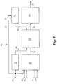
- the device 14 shown in FIG. 2 for generating card-normalized images it is possible to use the currently recorded video images, e.g. from the in Fig. 1 shown object field 9 to produce an image, for example, a look points to the recorded object field from a spatial point P ', which is perpendicular above the point M and at the same height above sea level (normal zero) as the point P in space is arranged, the line of sight also being in the north direction N '.
- the device 14 is for Generate card-standardized images using two electronic video cameras (not shown in more detail), whose video output signals 15, 16 and their each Signals 20, 21 describing the current field of view angle with a synchronization and Scaling device 22 are connected.
- This synchronization and scaling device 22 brings; if necessary, the signals from the two cameras on the same TV clock, so it synchronizes, for example, phase-shifted clocks and also different frequencies of the cameras.
- the device 22 also allows one Standardization or scaling of the images of the cameras to a uniform one Magnification, so that the images of one camera, for example, enlarged or the Images from the other camera are reduced.
- the synchronization and scaling device 22 therefore takes into account different spectral ranges and visual field angles of cameras installed on aircraft 1. Provided that the image format of the one camera image is Image format of the other camera image falls below that in the image concerned missing marginal areas filled in black.
- the device 14 has a write address mechanism provided with the signal clock 23 24 for generating a registration clock 25 with which the synchron mixed and scaled signal 26 at the output of the synchronization and Scaling device 22 is written into an image memory 27.
- the signal 26 contains the recorded image information in the form of a scanning grid.
- the write address mechanism 24 serves to assign the image information to one specific memory location in the image memory 27, the write-in clock 25 sets, for example storage of image information line by line.
- the device 14 has a delivery address mechanism 30
- Reading the image information from the image memory 27 taking into account the Signal clock 23 and the geometric configurations, in particular the spatial position and the pivot angle of the cameras, in the form of a combined signal 31 by means of a Geometrically modified readout grid having reading clock 32 on the readout address mechanism 30 is preferably a process computer in which in addition to the signal clock other boundary conditions can be entered when taking the picture.
- the read-out address mechanism 30 is also referred to as a readout grid generator, since it is a television-synchronous one Readout grid is generated.
- the read-out address mechanism 30 serves the stored image information in a modified manner in the form of a geometrically modified readout grid, i.e. in the form of standardized image information 33, read out from the image memory 27.
- the device 14 contains a signal converter 34, for example a video image synthesizer for converting the read image information 33 into one the signal 35 representing the card-normalized image.
- the signal 35 for example a Video signal, contains the data required for the card-standardized video image Information so that a so-called card coverage between the latter Video image and the geodetic coordinate network K (see. Fig. 1) is possible.
- the pictures taken with the camera or cameras are video pictures and Scanning grid and reading grid line-shaped television grid.
- the image memory 27 is on analog optoelectronic image memory, for example an image converter or television standard converter, or a digital electronic image memory. Registered mail and In the case of an analog image memory, the image information is read out by Electron beams generated by electronic or electromagnetic deflection according to the Scanning, readout grids are performed, and in the case of a digital image memory mathematical address operations.
- FIG. 1 that takes place in space point P on the aircraft 1, for example one unmanned observation drone, camera arranged aerial photos on the normalization the signals characterizing the aerial picture are carried out with the aid of the read-out address mechanism 30 taking into account the spatial position of the aircraft 1, i.e. especially the azimuth, Pitch and roll angle, the swivel angle, in particular the longitudinal and Transverse angle, the camera relative to the aircraft and the geodetic coordinates of the Space points P of the aircraft 1 and the height of the plumb point L above sea level.
- the spatial position of the aircraft i.e. especially the azimuth, Pitch and roll angle, the swivel angle, in particular the longitudinal and Transverse angle, the camera relative to the aircraft and the geodetic coordinates of the Space points P of the aircraft 1 and the height of the plumb point L above sea level.
- the camera provided on the aircraft 1 in the spatial point P observes the object field 9 on the ground at an oblique angle ⁇ (angle MPL) against the vertical and in a direction of the optical axis 4 (image perpendicular) rotated by an azimuth angle ⁇ relative to the north direction N or N ' 2.
- the image points of the original image recorded by the camera are described by image center-centered, Cartesian coordinates x original , y original in this image plane, for example the plane of the flat electronic scanning sensor.
- the focal length of the lens is f.
- the synchronization and scaling device 22 can standardize by analog Means, preferably a change in size of the scanning grid, or by digital means, preferably a linear transformation of the registration addresses with respect to a Enlargement or reduction.
- the individual components of the Device 14 according to the invention can be in analog, digital or hybrid technology be executed.
Landscapes
- Engineering & Computer Science (AREA)
- Multimedia (AREA)
- Physics & Mathematics (AREA)
- General Physics & Mathematics (AREA)
- Radar, Positioning & Navigation (AREA)
- Remote Sensing (AREA)
- Image Processing (AREA)
- Closed-Circuit Television Systems (AREA)
- Processing Or Creating Images (AREA)
Abstract
Description
- Fig. 1
- eine schematische, perspektivische Ansicht einer geometrischen Anordnung bei einer Luftbildaufnahme mit Hilfe eines Fluggerätes, und
- Fig. 2
- schematische Darstellung einer Vorrichtung zum Erzeugen kartennormierter, mittels wenigstens einer elektronischen Kamera aufgenommener Bilder.
Claims (8)
- Vorrichtung zum Erzeugen kartennormierter, mittels wenigstens einer elektronischen Kamera, insbesondere einer Videokamera, aufgenommener Bilder,
gekennzeichnet durchein Schreib-Adreßwerk (24) zum Erzeugen eines Einschreibtaktes (25),einen Bildspeicher (27), in den die aufgenommene, in Form eines Abtastrasters vorliegende Bildinformation mittels des Einschreibtaktes (25) einschreibbar ist,ein Auslese-Adreßwerk (30) zum Auslesen der Bildinformation aus dem Bildspeicher (27) unter Berücksichtigung des Signaltaktes (23) und der geometrischen Konfigurationen, insbesondere der Raumlage und der Schwenkwinkel der wenigstens einen Kamera, mittels eines ein geometrisch verändertes Ausleseraster aufweisenden Lesetaktes (32), undeinen Signalwandler (34) zum Unwandeln der ausgelesenen Bildinformation (33) in ein das kartennormierte Bild darstellendes Signal (35). - Vorrichtung nach Anspruch 1, dadurch gekennzeichnet, daß die Bilder Videobilder sind und daß Abtastraster sowie Ausleseraster zeilenförmige Fernsehraster sind.
- Vorrichtung nach Anspruch 1 oder 2, dadurch gekennzeichnet, daß der Bildspeicher (27) ein analoger optoelektronischer Bildspeicher, vorzugsweise ein Bildwandler oder Fernseh-Normwandler, oder ein digitaler elektronischer Bildspeicher ist, wobei das Einschreiben und Auslesen der Bildinformation im Falle eines analogen Bildspeichers durch Elektronenstrahlen, die durch elektronische oder elektromagnetische Ablenkung gemäß den Abtast-, Ausleserastern geführt sind, und im Falle eines digitalen Bildspeichers gemäß mathematischer Adreßoperationen erfolgt.
- Vorrichtung nach einem der Ansprüche 1 bis 3, dadurch gekennzeichnet, daß die wenigstens eine Kamera an einem Fluggerät (1), vorzugsweise an einer unbemannten Beobachtungsdrohne, angebracht ist, die Bilder Luftbilder sind und das Auslesen der Bildinformation unter Berücksichtigung der Raumlage des Fluggerätes (1), insbesondere des Azimut-, Nick- und Rollwinkels, der Schwenkwinkel, insbesondere des Längs- und Querwinkels, der wenigstens einen Kamera relativ zum Fluggerät (1), der geodätischen Koordinaten des Raumpunktes (P) des Fluggerätes (1) und der Höhe des Lotpunktes (L) über Normal Null erfolgt.
- Vorrichtung nach einem der vorhergehenden Ansprüche, dadurch gekennzeichnet, daß der Signalwandler (34) ein Videobild-Synthetisator ist.
- Vorrichtung nach einem der vorhergehenden Ansprüche, dadurch gekennzeichnet, daß bei Verwendung mehrerer, insbesondere spektral unterschiedlicher Kameras eine dem Bildspeicher (27) vorgeschaltete und mit diesem verbundene Synchronisierungs- und Skalierungseinrichtung (22) vorgesehen ist, welche die von den Kameras aufgenommene Bildinformation auf einen einheitlichen Abbildungsmaßstab normiert, mischt und hinsichtlich des Signaltaktes (23) synchronisiert.
- Vorrichtung nach Anspruch 6, dadurch gekennzeichnet, daß die Synchronisierungs- und Skalierungseinrichtung (22) die Normierung durch analoge Mittel, vorzugsweise eine Größenveränderung des Abtastrasters, oder durch digitale Mittel, vorzugsweise eine lineare Transformation der Einschreibadressen hinsichtlich einer Vergrößerung oder Verkleinerung, herbeiführt.
- Vorrichtung nach einem der vorhergehenden Ansprüche, dadurch gekennzeichnet, daß das kartennormierte Bild zwecks Deckung mit einer Landkarte auf eine senkrechte und nach Norden hin orientierte Blickrichtung ausgerichtet ist.
Applications Claiming Priority (2)
| Application Number | Priority Date | Filing Date | Title |
|---|---|---|---|
| DE1996145981 DE19645981C2 (de) | 1996-11-07 | 1996-11-07 | Vorrichtung zum Erzeugen kartennormierter Bilder |
| DE19645981 | 1996-11-07 |
Publications (2)
| Publication Number | Publication Date |
|---|---|
| EP0841534A2 true EP0841534A2 (de) | 1998-05-13 |
| EP0841534A3 EP0841534A3 (de) | 1999-07-14 |
Family
ID=7810963
Family Applications (1)
| Application Number | Title | Priority Date | Filing Date |
|---|---|---|---|
| EP97117792A Withdrawn EP0841534A3 (de) | 1996-11-07 | 1997-10-14 | Vorrichtung zum Erzeugen kartennormierter Bilder |
Country Status (2)
| Country | Link |
|---|---|
| EP (1) | EP0841534A3 (de) |
| DE (1) | DE19645981C2 (de) |
Families Citing this family (3)
| Publication number | Priority date | Publication date | Assignee | Title |
|---|---|---|---|---|
| DE29906968U1 (de) | 1999-04-19 | 1999-08-26 | Prangley, Roger, 86836 Graben | Vorrichtung zur geophysikalischen Erkundung von Arealen |
| DE10132929B4 (de) * | 2001-07-06 | 2006-06-01 | Funkwerk Plettac Electronic Gmbh | Verfahren und Vorrichtung zur Steuerung von Schwenk-Neige-Bewegungen einer Kamera |
| DE102008012751B4 (de) | 2008-03-05 | 2010-02-25 | Wolfgang Folger | Verfahren zur Erstellung von Abbildungen von über das Internet recherchierten Zielobjekten |
Family Cites Families (4)
| Publication number | Priority date | Publication date | Assignee | Title |
|---|---|---|---|---|
| US4600945A (en) * | 1983-03-31 | 1986-07-15 | Rca Corporation | Digital video processing system with raster distortion correction |
| GB2149258B (en) * | 1983-11-04 | 1987-03-11 | Ferranti Plc | Image correction system |
| US5467271A (en) * | 1993-12-17 | 1995-11-14 | Trw, Inc. | Mapping and analysis system for precision farming applications |
| US5596494A (en) * | 1994-11-14 | 1997-01-21 | Kuo; Shihjong | Method and apparatus for acquiring digital maps |
-
1996
- 1996-11-07 DE DE1996145981 patent/DE19645981C2/de not_active Expired - Fee Related
-
1997
- 1997-10-14 EP EP97117792A patent/EP0841534A3/de not_active Withdrawn
Also Published As
| Publication number | Publication date |
|---|---|
| DE19645981A1 (de) | 1998-05-14 |
| EP0841534A3 (de) | 1999-07-14 |
| DE19645981C2 (de) | 1999-07-01 |
Similar Documents
| Publication | Publication Date | Title |
|---|---|---|
| DE69515087T2 (de) | Verfahren und Vorrichtung zur hemisphärischen Bildaufnahme | |
| DE69232663T2 (de) | Rundumsichtausrichtungssystem mit bewegungsloser kamera | |
| DE3708683C2 (de) | Verfahren zur Bestimmung von Lageänderungen einer bewegten Bildsensorplattform | |
| EP0326128B1 (de) | Verfahren und Einrichtung zur Fernerkundung der Erde | |
| DE60213526T2 (de) | Verfahren und System zur Verbesserung des Situationsbewusstseins von Kommando-Kontrolleinheiten | |
| DE69430012T2 (de) | Auf einem luftfahrzeug angebrachter integrierter fotoapparat | |
| DE3043710C2 (de) | ||
| EP2464098B1 (de) | Umfeld-Darstellungsvorrichtung sowie ein Fahrzeug mit einer derartigen Umfeld-Darstellungsvorrichtung und Verfahren zur Darstellung eines Panoramabildes | |
| EP1301825B1 (de) | Kamerasystem mit mindestens zwei ersten und zweiten kameras | |
| DE3486295T2 (de) | Bildverzerrungskorrektursystem für elektro-optische Bildsensoren. | |
| DE3219032A1 (de) | Stereophotogrammetrisches aufnahme- und auswerteverfahren sowie auswertevorrichtung | |
| DE19851000A1 (de) | Projektionsanordnung mit einem Projektor und einem Ablenkspiegel | |
| DE102007030786A1 (de) | Vermessungsgerät | |
| DE202017104934U1 (de) | Mehrstufiges Kameraträgersystem für die stereoskope Bildaufnahme | |
| EP0310791B1 (de) | Vorrichtung zur Aufnahme einer Szene, insbesondere zwecks deren Wiedergabe auf dem Bildschirm eines Bildschirmgeräts | |
| DE69102724T2 (de) | Verfahren zum Einstellen der stereoskopischen Konvergenz in einer stereoskopischen, bilderzeugenden Vorrichtung. | |
| DE112004002767T5 (de) | Reflexionssperre für Panoramadisplay | |
| DE69633589T2 (de) | Verfahren und Gerät zur Verarbeitung von visuellen Informationen | |
| DE19815106A1 (de) | Verfahren zum Messen von Kamera- und Linseneigenschaften zur Kameranachführung | |
| DE102004017730B4 (de) | Verfahren zur Rotationskompensation sphärischer Bilder | |
| DE102019008472B4 (de) | Multilinsen-Kamerasystem und Verfahren zur hyperspektralen Aufnahme von Bildern | |
| DE69618887T2 (de) | Asphärische Elemente für Infrarot-Abbildungssystem | |
| DE19645981C2 (de) | Vorrichtung zum Erzeugen kartennormierter Bilder | |
| DE102005046735A1 (de) | Verfahren zur rechnergestützten Ermittlung einer Position in einer Landkarte, Navigationsvorrichtung und Mobilfunktelefon | |
| DE69512487T2 (de) | Sensoreinrichtung zur Erderfassung für einen Satelliten oder Ähnliches mit einer pyroelektrischen Detektormatrix |
Legal Events
| Date | Code | Title | Description |
|---|---|---|---|
| PUAI | Public reference made under article 153(3) epc to a published international application that has entered the european phase |
Free format text: ORIGINAL CODE: 0009012 |
|
| AK | Designated contracting states |
Kind code of ref document: A2 Designated state(s): AT BE CH DE DK ES FI FR GB GR IE IT LI LU MC NL PT SE |
|
| AX | Request for extension of the european patent |
Free format text: AL;LT;LV;RO;SI |
|
| PUAL | Search report despatched |
Free format text: ORIGINAL CODE: 0009013 |
|
| AK | Designated contracting states |
Kind code of ref document: A3 Designated state(s): AT BE CH DE DK ES FI FR GB GR IE IT LI LU MC NL PT SE |
|
| AX | Request for extension of the european patent |
Free format text: AL;LT;LV;RO;SI |
|
| RIC1 | Information provided on ipc code assigned before grant |
Free format text: 6G 01C 11/02 A, 6G 06T 3/00 B |
|
| AKX | Designation fees paid | ||
| REG | Reference to a national code |
Ref country code: DE Ref legal event code: 8566 |
|
| STAA | Information on the status of an ep patent application or granted ep patent |
Free format text: STATUS: THE APPLICATION IS DEEMED TO BE WITHDRAWN |
|
| 18D | Application deemed to be withdrawn |
Effective date: 20000115 |