EP0841239B1 - Starres Rohr mit Rückschlagventil für einen Hydraulikkreislauf - Google Patents
Starres Rohr mit Rückschlagventil für einen Hydraulikkreislauf Download PDFInfo
- Publication number
- EP0841239B1 EP0841239B1 EP97440102A EP97440102A EP0841239B1 EP 0841239 B1 EP0841239 B1 EP 0841239B1 EP 97440102 A EP97440102 A EP 97440102A EP 97440102 A EP97440102 A EP 97440102A EP 0841239 B1 EP0841239 B1 EP 0841239B1
- Authority
- EP
- European Patent Office
- Prior art keywords
- rigid
- rigid tube
- return valve
- recess
- tube
- Prior art date
- Legal status (The legal status is an assumption and is not a legal conclusion. Google has not performed a legal analysis and makes no representation as to the accuracy of the status listed.)
- Expired - Lifetime
Links
- 210000000056 organ Anatomy 0.000 claims description 13
- 210000002445 nipple Anatomy 0.000 claims description 9
- 238000002788 crimping Methods 0.000 claims description 8
- 230000000284 resting effect Effects 0.000 claims 4
- 230000037431 insertion Effects 0.000 claims 1
- 238000003780 insertion Methods 0.000 claims 1
- 239000011324 bead Substances 0.000 description 8
- 239000012530 fluid Substances 0.000 description 7
- 230000004308 accommodation Effects 0.000 description 2
- 239000011248 coating agent Substances 0.000 description 1
- 238000000576 coating method Methods 0.000 description 1
- 230000000694 effects Effects 0.000 description 1
- 238000003754 machining Methods 0.000 description 1
- 238000004519 manufacturing process Methods 0.000 description 1
Images
Classifications
-
- B—PERFORMING OPERATIONS; TRANSPORTING
- B62—LAND VEHICLES FOR TRAVELLING OTHERWISE THAN ON RAILS
- B62D—MOTOR VEHICLES; TRAILERS
- B62D5/00—Power-assisted or power-driven steering
- B62D5/06—Power-assisted or power-driven steering fluid, i.e. using a pressurised fluid for most or all the force required for steering a vehicle
- B62D5/062—Details, component parts
Definitions
- the invention relates to a rigid pipe or a flexible pipe fitted a rigid tube for a hydraulic circuit, such as a system motor vehicle steering assistance.
- the invention will find its application whenever it is appropriate to install a non-return valve in a hydraulic circuit.
- the invention will be of particular utility in the automotive industry when it comes to designing a steering assistance system.
- Such a system is composed of a number of organs such that a pump, a valve, a cylinder and rigid tubes or pipes flexible connecting these different organs.
- this check valve is often arranged immediately to the entry or exit of one of the organs of the assistance system of management. It can also be placed in a valve holder interposed at, for example, a connection hose hydraulic.
- a motor vehicle steering assistance device comprises tubes inside which circulates a hydraulic fluid.
- the connection between two of these tubes is made at by means of a valve holder comprising a well for receiving a tube which is fitted with a nut connection system intended for cooperate with a thread formed inside said well.
- a housing for the reception of the non-return valve.
- the present invention proposes to provide a solution advantageous to the above problems.
- the invention relates to a rigid tube intended to be connected to a flexible hose and / or any part of a hydraulic circuit, in particular an assistance system motor vehicle steering, which hydraulic system comprises a non-return valve, characterized in that it comprises along its length and internally, a form-fitting housing for the reception of said non-return valve.
- the configuration of the organs of the assistance system of steering just like the tube connection systems to the level of these organs are completely independent of characteristics of the non-return valve.
- everything particularly to a nut connection system can advantageously be substituted a so-called connection system fast flanged. It will be observed, in this regard, that a mounting with a nut is generally less suitable for a possible robotization, unlike assembly systems whose assembly operations break down into simple movements and unidirectional.
- the invention relates to a rigid tube 1 forming part of a circuit any hydraulic system, for example an assistance system motor vehicle steering.
- this rigid tube 1 can be connected to a flexible hose and / or to any member of the hydraulic circuit.
- an assistance system direction it usually breaks down into a pump, a regulation valve, and a hydraulic cylinder.
- the use of the object of the present invention is justified when there is reason to control the flow of a fluid inside a tube. Such a problem is encountered when one wishes to control a Unidirectional fluid flow, especially in the case of a return of fluid during a feedback from the assistance system of direction. This can be achieved through the use of a valve non-return 2 arranged on the path of the fluid.
- the rigid tube 1 has along its length and internally, a housing 3 of adjusted shape for the reception of said non-return valve 2.
- Said housing 3 can be in various forms depending on the type of achievement considered, in particular in the form of a annular groove 4, as visible in Figures 1 and 2, hence This results in a bulge 5 on the surface of the rigid tube 1.
- the housing 3 is delimited axially and on the one hand and on the other by at least one radial shoulder 6A, 6B. Between these shoulders 6A, 6B takes position the non-return valve 2.
- this non-return valve 2 can still be immobilized in the housing 3 via suitable means for example using an O-ring, a spring washer or other.
- Said housing 3 can also be presented, quite simply, under shape of a portion of the rigid tube 1 whose internal section is strictly adjusted to the external section of the non-return valve 2 authorizing its mounting in force.
- this accommodation 3 can be arranged in a place any along the rigid tube 1 and preferably on a rectilinear section of the latter. This therefore allows locate said non-return valve 2 along the rigid tube 1 of so as to avoid possible discomfort or in a position determined for obtaining an optimal acoustic behavior of the assembly in which this rigid tube 1 is integrated.
- Said rigid tube 1 can be provided, at its end 7, with means connection 8 intended to cooperate with one of the members 9 of the hydraulic circuit which, in the case of a particular application to a steering assistance system, comes in the form a pump, a valve or a jack. This is pictured schematically and partially in Figure 4.
- the means of connection 8 are of the screw-nut type as known in the art prior.
- This system is in the form of a nut 10 mounted on the end 7 of the rigid tube 1 which includes a bead 14 on which this nut 10 rests.
- This presents to one of its ends a threaded end 11 intended to cooperate with a threaded housing, not shown, formed, for example, on one of the organs 9 of the hydraulic circuit.
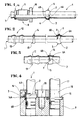
- FIG 2 shows an alternative embodiment of the device previous in which the rigid tube 1 always comprises, on its length, a housing 3 intended to receive, identically to the solution shown in Figure 1, the non-return valve 2.
- This housing 3 can advantageously be arranged at a distance any of the end 7 of said tube 1.
- this rigid tube 1 has a crimping system 12 in the form of a nipple 13 which represents the male part to be crimped, for example, in a pipe flexible.
- Said nipple 13 can be shaped as it is known in the prior art, in particular in French patent n ° 2675880.
- this nipple 13 has a bead 14 defining a shoulder 15 against which bears the end of the socket completing this crimping system 12.
- Figure 3 is a view similar to Figure 2 in which the rigid tube 1 is equipped with an identical crimping system 12.
- the housing 3 intended to receive the valve non-return 2 corresponds to the bead 14 constituting the shoulder 15 against which the socket of the crimping system 12 is intended to support.
- the housing 3, defined inside the rigid tube 1 and receiving the non-return valve 2, can contribute to the connection of the end of this rigid tube 1 on one of the organs 9 of the circuit hydraulics, including the steering assistance system. This is particularly the case when the housing 3 defines a bead 14A on the surface of this rigid tube 1.
- the housing 3 defines a bead 14A on the surface of this rigid tube 1.
- on such a bead 14A can bear a flange attachment 16 which is screwed onto member 9.
- the rigid tube 1 is immobilized in rotation by compared to said flange 16 allows, advantageously, during the mounting the assembly on member 9, positioning said tube rigid 1 angularly relative to the latter. This allows offer a device ready to be positioned without requiring adjustment later on the vehicle assembly line.
- FIG. 4 shows two rigid tubes 1, 17, connected to member 9, the first, 1, integrating the valve non-return 2 and comprising the fixing flange 16 ensuring, simultaneously, maintaining the two tubes 1, 17 on this member 9.
- Such a flange 16 has a lateral projection 18 at the level which is cut to the dimensions adjusted to the section of the second rigid tube 17. In this way, this flange 16 can be engaged on this second rigid tube 17, at the rear of a shoulder 19 fitted to the latter, once the latter is connected to the member 9, at the same time of mounting the first rigid tube 1 on this last.
- the housing 3 intended to receive the non-return valve 2 can be arranged indifferently on the first rigid tube 1 or on the second rigid tube 17. Consequently, said valve non-return 2 as well as the bead 14A defined by said housing 3, can be arranged on any one of these two tubes. Also, the fixing flange 16 bearing on said bead 14A, can be indifferently immobilized on the first tube rigid 1 or the other 17.
- these two tubes can be held in position by via a single fixing screw 20 passing through the flange fastening 16 and coming to cooperate with the member 9.
- the implementation of the invention is not only easy but considerably facilitates the design and assembly of a hydraulic circuit such as a steering assistance system incorporating a non-return valve.
Landscapes
- Engineering & Computer Science (AREA)
- Chemical & Material Sciences (AREA)
- Combustion & Propulsion (AREA)
- Transportation (AREA)
- Mechanical Engineering (AREA)
- Fluid-Pressure Circuits (AREA)
- Power Steering Mechanism (AREA)
- Valves And Accessory Devices For Braking Systems (AREA)
- Rigid Pipes And Flexible Pipes (AREA)
- Quick-Acting Or Multi-Walled Pipe Joints (AREA)
- Check Valves (AREA)
Claims (11)
- Steifes Rohr (1) zur Verbindung mit einem biegsamen Rohr und/oder irgendeinem Organ eines Hydraulikkreises, nämlich eines Hilfskraft-Lenkungssystems eines Kraftfahrzeugs, welcher Hydraulikkreis eine Rückschlagklappe (2) umfaßt, dadurch gekennzeichnet, daß es in seinem Innneren und über seine Länge einen Hohlraum (3) einer zum Aufnehmen der genannten Rückschlagklappe (2) angepaßten Form umfaßt.
- Steifes Rohr (1) nach Anspruch 1, dadurch gekennzeichnet, daß die Rückschlagklappe (2) im Hohlraum (3) mittels zwei Ansätze (6A, 6B), die diesen letzten achsial begrenzen, festgeklemmt wird.
- Steifes Rohr (1) nach Anspruch 1, dadurch gekennzeichnet, daß die Rückschlagklappe (2) im Hohlraum (3) über geeignete Mittel, wie einen O-ring, eine Federscheibe oder dergleichen, festgeklemmt wird.
- Steifes Rohr (1) nach Anspruch 1, dadurch gekennzeichnet, daß die Rückschlagklappe (3) als ein Teil des Steifes Rohres (1) ausgestaltet ist, dessen innerer Querschnitt dem äußeren Querschnitt der Rückschlagklappe (2) genau angepaßt ist, was ihre gezwungene Montage erlaubt.
- Steifes Rohr (1) nach irgendeinem der vorgehenden Ansprüche, dadurch gekennzeichnet, daß der Hohlraum (3) zur Aufnahme der Rückschlagklappe (2) an irgendeiner Stelle entlang den genannten steifen Rohr (1), vorzugsweise auf einem geradlinigen Abschnitt dieses letzten, vorgesehen ist.
- Steifes Rohr (1) nach irgendeinem der Ansprüche 1 bis 4, umfassend an einem Ende ein Fassungssystem (12), das als ein Nippel (13) ausgestaltet ist, der einen Wulst (14) aufweist, der einen Ansatz (15) definiert, an den eine Büchse, die dieses Fassungssystem (12) ergänzt, anlehnen kann, dadurch gekennzeichnet, daß der Hohlraum (3) zur Aufnahme der Rückschlagklappe (2) dem Wulst (14) entspricht, der den Ansatz (15) bildet, an den die genannte Büchse des Fassungssystems (12) anlehnen können muß.
- Steifes Rohr (1) nach irgendeinem der Ansprüche 1 bis 4, dadurch gekennzeichnet, daß der Hohlraum (3), der die Rückschlagklappe (2) aufnimmt, an der Oberfläche des steifen Rohres (1) einen Wulst (14A) definiert, an den ein Befestigungsflansch (16) anlehnen kann.
- Steifes Rohr (1) nach Anspruch 7, dadurch gekennzeichnet, daß der Befestigungsflansch (16) drehfest an dem steifen Rohr (1) befestigt ist.
- Steifes Rohr (1) nach Anspruch 7 oder 8, dadurch gekennzeichnet, daß es während der Herstellung des Hohlraums (3) für die Rückschlagklappe (2) im Befestigungsflansch (16) eingewalzt wird, um den genannten Befestigungsflansch (16) drehfest an dem genannten steifen Rohr (1) zu befestigen.
- Anwendung des steifen Rohres (1), wie dieses in den vorgehenden Ansprüchen gekennzeichnet ist, für ein Hilfskraft-Lenkungssystem eines Kraftfahrzeugs, in dem eine Rückschlagklappe (2) integriert ist.
- Anwendung des steifen Rohres (1), wie dieses in den Ansprüchen 1 bis 9 gekennzeichnet ist, für ein Hilfskraft-Lenkungssystem, das ein Organ (9), wie eine Pumpe, ein Ventil oder eine Winde, umfaßt, an dem ein erstes steifes Rohr (1) und ein zweites steifes Rohr (17) angeschlossen sind, wobei das erste steife Rohr (1) an dessen Oberfläche einen Wulst (14A) umfaßt, der dem Hohlraum (3) zur Aufnahme der Rückschlagklappe (2) entspricht, wobei an diesem ersten steifen Rohr (1) außerdem ein Befestigungsflansch (16) drehfest befestigt ist, der an den Wulst (14A) anlehnt und einen seitlichen Auswuchs (18) umfaßt, der mit einem Ausschnitt versehen ist, dessen Abmessungen dem Querschnitt des zweiten steifen Rohres (17) angepaßt sind, was das Aufstecken dieses Befestigungsflansches (16) auf diesen zweiten steifen Rohr (17) erlaubt, hinter einem Ansatz (19), mit dem dieses letzte versehen ist, und zwar während der Verbindung dieser steifen Rohre (1) und (17) mit dem Organ (9) des genannten Hilfskraft-Lenkungssystems.
Applications Claiming Priority (2)
| Application Number | Priority Date | Filing Date | Title |
|---|---|---|---|
| FR9613920 | 1996-11-12 | ||
| FR9613920A FR2755743B1 (fr) | 1996-11-12 | 1996-11-12 | Tube rigide pour circuit hydraulique comportant un clapet anti-retour |
Publications (2)
| Publication Number | Publication Date |
|---|---|
| EP0841239A1 EP0841239A1 (de) | 1998-05-13 |
| EP0841239B1 true EP0841239B1 (de) | 2002-03-27 |
Family
ID=9497638
Family Applications (1)
| Application Number | Title | Priority Date | Filing Date |
|---|---|---|---|
| EP97440102A Expired - Lifetime EP0841239B1 (de) | 1996-11-12 | 1997-11-07 | Starres Rohr mit Rückschlagventil für einen Hydraulikkreislauf |
Country Status (6)
| Country | Link |
|---|---|
| EP (1) | EP0841239B1 (de) |
| AT (1) | ATE215035T1 (de) |
| DE (1) | DE69711325T2 (de) |
| ES (1) | ES2174206T3 (de) |
| FR (1) | FR2755743B1 (de) |
| PT (1) | PT841239E (de) |
Cited By (1)
| Publication number | Priority date | Publication date | Assignee | Title |
|---|---|---|---|---|
| DE102008064537A1 (de) | 2008-12-19 | 2010-06-24 | Dr. Ing. H.C. F. Porsche Aktiengesellschaft | Fluidleitung |
Families Citing this family (5)
| Publication number | Priority date | Publication date | Assignee | Title |
|---|---|---|---|---|
| FR2790239B1 (fr) * | 1999-02-26 | 2001-05-04 | Hutchinson | Procede de montage d'un clapet anti-retour dans un systeme hydraulique, en particulier un systeme de direction assistee pour vehicule automobile |
| JP4663867B2 (ja) * | 1999-11-09 | 2011-04-06 | ティッセンクルップ プレスタ シュテアーテク ゲゼルシヤフト ミツト ベシュレンクテル ハフツング | 油圧サ─ボ操向装置用の操向ダンパ─ |
| CN105042223A (zh) * | 2015-08-28 | 2015-11-11 | 安徽江淮汽车股份有限公司 | 一种转向器与转动管的连接机构 |
| FR3124566B1 (fr) | 2021-06-25 | 2023-05-12 | Hutchinson | Dispositif de raccordement fluidique et vanne inserable anti-retour pour vehicule |
| FR3124567B1 (fr) | 2021-06-25 | 2026-02-06 | Hutchinson | Dispositif de raccordement fluidique et vanne inserable anti-retour pour vehicule |
Family Cites Families (3)
| Publication number | Priority date | Publication date | Assignee | Title |
|---|---|---|---|---|
| DE2927039A1 (de) * | 1979-07-04 | 1981-01-15 | Zahnradfabrik Friedrichshafen | Hydraulische hilfskraftlenkung |
| US4673051A (en) * | 1986-03-10 | 1987-06-16 | General Motors Corporation | Power steering gear with two-way check valve |
| US5531287A (en) * | 1995-03-27 | 1996-07-02 | Chrysler Corporation | Power steering system with vibration and noise suppression |
-
1996
- 1996-11-12 FR FR9613920A patent/FR2755743B1/fr not_active Expired - Fee Related
-
1997
- 1997-11-07 EP EP97440102A patent/EP0841239B1/de not_active Expired - Lifetime
- 1997-11-07 DE DE69711325T patent/DE69711325T2/de not_active Expired - Lifetime
- 1997-11-07 PT PT97440102T patent/PT841239E/pt unknown
- 1997-11-07 ES ES97440102T patent/ES2174206T3/es not_active Expired - Lifetime
- 1997-11-07 AT AT97440102T patent/ATE215035T1/de not_active IP Right Cessation
Cited By (1)
| Publication number | Priority date | Publication date | Assignee | Title |
|---|---|---|---|---|
| DE102008064537A1 (de) | 2008-12-19 | 2010-06-24 | Dr. Ing. H.C. F. Porsche Aktiengesellschaft | Fluidleitung |
Also Published As
| Publication number | Publication date |
|---|---|
| ES2174206T3 (es) | 2002-11-01 |
| DE69711325D1 (de) | 2002-05-02 |
| DE69711325T2 (de) | 2002-11-07 |
| PT841239E (pt) | 2002-08-30 |
| EP0841239A1 (de) | 1998-05-13 |
| FR2755743B1 (fr) | 1998-12-31 |
| ATE215035T1 (de) | 2002-04-15 |
| FR2755743A1 (fr) | 1998-05-15 |
Similar Documents
| Publication | Publication Date | Title |
|---|---|---|
| EP1064489B1 (de) | Steck-kupplung für rohre | |
| EP1351848B1 (de) | Hauptzylinder und pneumatische stellgliedvorrichtung für ein bremssystem | |
| FR2742079A1 (fr) | Ajutage d'apport de liquide sur un outil rotatif | |
| EP4094003B1 (de) | Vorrichtung zum verbinden eines rohrförmigen elements | |
| FR2806771A1 (fr) | Ressort pneumatique comportant un amortisseur d'oscillations variable en fonction de la pression de support | |
| FR2839136A1 (fr) | Dispositif de raccordement etanche, en particulier pour un circuit d'admission d'air de moteur de vehicule automobile | |
| FR3087516A1 (fr) | Dispositif de raccordement instantane. | |
| EP0841239B1 (de) | Starres Rohr mit Rückschlagventil für einen Hydraulikkreislauf | |
| EP0501852B1 (de) | Vorrichtung zur Befestigung eines rohrförmigen Organs auf einem Rohrende eines Kupplungsteils, insbesondere eines Kraftfahrzeuges | |
| WO2000079172A1 (fr) | Dispositif de raccord etanche pour conduit de fluide, en particulier pour vehicule automobile | |
| FR2787549A1 (fr) | Element tubulaire de conduite comportant une partie longitudinale rigide et une partie longitudinale souple en une seule piece | |
| FR2475475A1 (fr) | Projecteur de vehicule comportant un bloc optique a dispositif perfectionne pour le montage dans la carrosserie ou dans un boitier | |
| FR3124567A1 (fr) | Dispositif de raccordement fluidique et vanne inserable anti-retour pour vehicule | |
| FR2617569A1 (fr) | Element de liaison entre un conduit et un composant | |
| FR2630188A3 (fr) | Canalisation pour liquide sous pression, en particulier pour vehicule | |
| FR2528942A1 (fr) | Assemblage par emboitement | |
| FR2818730A1 (fr) | Embout femelle pour coupleur | |
| FR2924193A1 (fr) | Raccord etanche et procede de montage d'un tel reccord | |
| FR2668240A1 (fr) | Dispositif de raccordement de deux tuyaux de part et d'autre d'un element de cloison. | |
| FR2750193A1 (fr) | Bague d'etancheite d'un arbre d'entrainement d'essuie-vitre | |
| EP0751337A1 (de) | Schalldämpfer für einen hydraulischen Schlauch | |
| FR2848962A1 (fr) | Dispositif de commande de frein a maitre-cylindre | |
| FR3098886A1 (fr) | Dispositif de raccordement fluidique de type cartouche | |
| FR2855240A1 (fr) | Procede et systeme pour raccorder de maniere etanche un embout tubulaire dans la paroi d'un conduit de transport d'un fluide | |
| WO2023285512A1 (fr) | Dispositif de fixation d'un élément sur une partie d'un véhicule automobile |
Legal Events
| Date | Code | Title | Description |
|---|---|---|---|
| PUAI | Public reference made under article 153(3) epc to a published international application that has entered the european phase |
Free format text: ORIGINAL CODE: 0009012 |
|
| AK | Designated contracting states |
Kind code of ref document: A1 Designated state(s): AT DE ES FR GB IT PT SE AT DE ES FR GB IT PT SE |
|
| AX | Request for extension of the european patent |
Free format text: AL;LT;LV;MK;RO;SI |
|
| 17P | Request for examination filed |
Effective date: 19980707 |
|
| AKX | Designation fees paid |
Free format text: AT DE ES FR GB IT PT SE |
|
| RBV | Designated contracting states (corrected) |
Designated state(s): AT DE ES FR GB IT PT SE |
|
| RBV | Designated contracting states (corrected) |
Designated state(s): AT DE ES FR GB IT PT SE |
|
| 17Q | First examination report despatched |
Effective date: 19991213 |
|
| GRAG | Despatch of communication of intention to grant |
Free format text: ORIGINAL CODE: EPIDOS AGRA |
|
| GRAG | Despatch of communication of intention to grant |
Free format text: ORIGINAL CODE: EPIDOS AGRA |
|
| GRAH | Despatch of communication of intention to grant a patent |
Free format text: ORIGINAL CODE: EPIDOS IGRA |
|
| GRAH | Despatch of communication of intention to grant a patent |
Free format text: ORIGINAL CODE: EPIDOS IGRA |
|
| REG | Reference to a national code |
Ref country code: GB Ref legal event code: IF02 |
|
| GRAA | (expected) grant |
Free format text: ORIGINAL CODE: 0009210 |
|
| AK | Designated contracting states |
Kind code of ref document: B1 Designated state(s): AT DE ES FR GB IT PT SE |
|
| REF | Corresponds to: |
Ref document number: 215035 Country of ref document: AT Date of ref document: 20020415 Kind code of ref document: T |
|
| REF | Corresponds to: |
Ref document number: 69711325 Country of ref document: DE Date of ref document: 20020502 |
|
| REG | Reference to a national code |
Ref country code: PT Ref legal event code: SC4A Free format text: AVAILABILITY OF NATIONAL TRANSLATION Effective date: 20020531 |
|
| REG | Reference to a national code |
Ref country code: ES Ref legal event code: FG2A Ref document number: 2174206 Country of ref document: ES Kind code of ref document: T3 |
|
| PLBE | No opposition filed within time limit |
Free format text: ORIGINAL CODE: 0009261 |
|
| STAA | Information on the status of an ep patent application or granted ep patent |
Free format text: STATUS: NO OPPOSITION FILED WITHIN TIME LIMIT |
|
| 26N | No opposition filed |
Effective date: 20021230 |
|
| PGFP | Annual fee paid to national office [announced via postgrant information from national office to epo] |
Ref country code: SE Payment date: 20091106 Year of fee payment: 13 Ref country code: ES Payment date: 20091201 Year of fee payment: 13 Ref country code: DE Payment date: 20091105 Year of fee payment: 13 Ref country code: AT Payment date: 20091111 Year of fee payment: 13 |
|
| PGFP | Annual fee paid to national office [announced via postgrant information from national office to epo] |
Ref country code: PT Payment date: 20091103 Year of fee payment: 13 |
|
| PGFP | Annual fee paid to national office [announced via postgrant information from national office to epo] |
Ref country code: IT Payment date: 20091113 Year of fee payment: 13 Ref country code: GB Payment date: 20091104 Year of fee payment: 13 Ref country code: FR Payment date: 20091203 Year of fee payment: 13 |
|
| REG | Reference to a national code |
Ref country code: PT Ref legal event code: MM4A Free format text: LAPSE DUE TO NON-PAYMENT OF FEES Effective date: 20110509 |
|
| REG | Reference to a national code |
Ref country code: SE Ref legal event code: EUG |
|
| GBPC | Gb: european patent ceased through non-payment of renewal fee |
Effective date: 20101107 |
|
| PG25 | Lapsed in a contracting state [announced via postgrant information from national office to epo] |
Ref country code: PT Free format text: LAPSE BECAUSE OF NON-PAYMENT OF DUE FEES Effective date: 20110509 |
|
| REG | Reference to a national code |
Ref country code: FR Ref legal event code: ST Effective date: 20110801 |
|
| PG25 | Lapsed in a contracting state [announced via postgrant information from national office to epo] |
Ref country code: AT Free format text: LAPSE BECAUSE OF NON-PAYMENT OF DUE FEES Effective date: 20101107 |
|
| REG | Reference to a national code |
Ref country code: DE Ref legal event code: R119 Ref document number: 69711325 Country of ref document: DE Effective date: 20110601 Ref country code: DE Ref legal event code: R119 Ref document number: 69711325 Country of ref document: DE Effective date: 20110531 |
|
| PG25 | Lapsed in a contracting state [announced via postgrant information from national office to epo] |
Ref country code: SE Free format text: LAPSE BECAUSE OF NON-PAYMENT OF DUE FEES Effective date: 20101108 Ref country code: DE Free format text: LAPSE BECAUSE OF NON-PAYMENT OF DUE FEES Effective date: 20110531 |
|
| PG25 | Lapsed in a contracting state [announced via postgrant information from national office to epo] |
Ref country code: FR Free format text: LAPSE BECAUSE OF NON-PAYMENT OF DUE FEES Effective date: 20101130 |
|
| PG25 | Lapsed in a contracting state [announced via postgrant information from national office to epo] |
Ref country code: GB Free format text: LAPSE BECAUSE OF NON-PAYMENT OF DUE FEES Effective date: 20101107 |
|
| PG25 | Lapsed in a contracting state [announced via postgrant information from national office to epo] |
Ref country code: IT Free format text: LAPSE BECAUSE OF NON-PAYMENT OF DUE FEES Effective date: 20101107 |
|
| REG | Reference to a national code |
Ref country code: ES Ref legal event code: FD2A Effective date: 20120110 |
|
| PG25 | Lapsed in a contracting state [announced via postgrant information from national office to epo] |
Ref country code: ES Free format text: LAPSE BECAUSE OF NON-PAYMENT OF DUE FEES Effective date: 20101108 |