EP0841030A1 - Bouilloire - Google Patents
Bouilloire Download PDFInfo
- Publication number
- EP0841030A1 EP0841030A1 EP97308995A EP97308995A EP0841030A1 EP 0841030 A1 EP0841030 A1 EP 0841030A1 EP 97308995 A EP97308995 A EP 97308995A EP 97308995 A EP97308995 A EP 97308995A EP 0841030 A1 EP0841030 A1 EP 0841030A1
- Authority
- EP
- European Patent Office
- Prior art keywords
- vessel
- plate
- flange
- liquid heating
- sealing
- Prior art date
- Legal status (The legal status is an assumption and is not a legal conclusion. Google has not performed a legal analysis and makes no representation as to the accuracy of the status listed.)
- Withdrawn
Links
Images

Classifications
-
- A—HUMAN NECESSITIES
- A47—FURNITURE; DOMESTIC ARTICLES OR APPLIANCES; COFFEE MILLS; SPICE MILLS; SUCTION CLEANERS IN GENERAL
- A47J—KITCHEN EQUIPMENT; COFFEE MILLS; SPICE MILLS; APPARATUS FOR MAKING BEVERAGES
- A47J27/00—Cooking-vessels
- A47J27/21—Water-boiling vessels, e.g. kettles
- A47J27/21008—Water-boiling vessels, e.g. kettles electrically heated
- A47J27/21041—Water-boiling vessels, e.g. kettles electrically heated with heating elements arranged outside the water vessel
Definitions
- the present invention relates to liquid heating vessels and in particular to portable liquid heating vessels having metal bodies, such as metal kettles and 'wasserkochers'.
- a heating element is brazed or otherwise fixedly mechanically connected to the vessel base.
- the element is mounted to a plate which is itself mounted as the base of the vessel body, for example by being rolled over a flange provided on the vessel body.
- the problem with such arrangements is that the element is normally attached to the vessel base quite early in its construction, before the vessel body is polished, before controls etc. are mounted to the vessel and before final testing. If the element is found to be faulty at this final testing stage, then it cannot be removed from the vessel base, and the whole vessel must be scrapped. Clearly this is extremely expensive. Furthermore, if the element should fail in the field, there is no way in which it can be removed and replaced, and a potentially expensive purchase must be replaced.
- the present invention seeks to mitigate the above problems, and from a first aspect comprises a liquid heating vessel comprising a metal vessel body, a heating element provided on the underside of a metal plate which closes the bottom of the vessel, the vessel and the plate having respective sealing flanges, with sealing means arranged between the sealing flanges, the vessel being provided with a plurality of tongues extending from the vessel sealing flange, which tongues clamp the heater plate to the vessel and compress the sealing means between the sealing flanges.
- a heater plate is clamped in the base of a liquid heating vessel by means of a plurality of spaced clamping tongues associated with a sealing flange on the vessel. Not only does this provide an extremely satisfactory way in which to mount the heater plate in the first instance, but it means that, if necessary, it may be removed by deforming back the clamping tongues. A new plate may then be positioned and clamped using the tongues, thereby saving the cost of having potentially to replace the whole vessel.
- the metal plate may be, for example, a stainless steel plate.
- the plate may have been treated or coated on its vessel facing side to improve its appearance or corrosion resistance.
- the seal may be arranged so to be compressed radially or axially of the vessel, or in a combination of these directions.
- the plate may comprise a peripheral L-shaped or U-shaped flange for receiving the a seal.
- the seal may have a diameter which is slightly smaller than the outer diameter of the plate flange on which it is received.
- One of the flanges, most preferably that of the vessel base may be inclined, so as to compress the seal in two directions upon fastening of the plate to the base.
- the sealing flange provided on the vessel has the shape of an inverted L.
- the plate may have a number of slots to receive the clamping tongues of the vessel, and which also serve to locate the plate relative to the vessel.
- the vessel sealing flange is preferably formed on a portion of the vessel base spaced radially inwardly of the bottom of the vessel wall.
- the region of the vessel base on which the vessel sealing flange is formed may be an integrally formed part of the vessel, or a separate component, e.g. a mounting ring, which is itself fixedly mounted to the vessel, for example by welding. This may facilitate manufacture of the vessel as a whole.
- the heating element may be a conventional sheathed coil element, but preferably it is a thick film heating element.
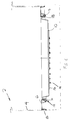
- a liquid heating vessel 2 comprises a stainless steel vessel body wall 4, a stainless steel mounting ring 6 fixedly secured to the bottom 8 of the vessel wall, for example by welding, and a stainless steel element carrier plate 10 releasably fastened to the mounting ring 6 through releasable fastening means indicated generally by 12.
- a seal 13 is compressed between the carrier plate 10 and the mounting ring 6.
- the element carrier plate 10 is covered by a base cover 15, shown schematically in dotted lines.
- the plate 10 carries a thick film printed element 14 which is laid down onto an ceramic insulating layer 16 provided on the underside of the plate 10.
- a thick film printed element 14 which is laid down onto an ceramic insulating layer 16 provided on the underside of the plate 10.
- Such elements are well known and will not be described further.
- the carrier plate 10 is of a type similar to that described in WO 96/18331, and comprises a peripheral U-shaped groove 18, having an inner wall 20, an outer wall 22 and a base wall 24.
- a series of six circumferentially equispaced slots 26 is formed in the outer and base walls 22,24 of the groove 18, the slots being of sufficient circumferential width to accommodate fastening tongues 30 provided on the mounting ring 6 as will be described further below.
- the mounting ring 6 comprises a radially outer flange 32 for engagement with and attachment to the vessel wall 4, and a radially inner flange 34 for mounting the element carrier plate 10.
- the flanges are joined by a web 36.
- the innermost diameter D I of the flange 34 is slightly larger than the diameter Do of the inner wall 20 of the peripheral groove 18 of the carrier plate.
- the flange 34 is inclined radially outwardly away from the web 36, to define an included angle of about 60° therebetween.
- Six circumferentially equispaced fastening tongues 30 extend from the lower end 38 of the flange 34 for engagement with the slots 26 in the groove 18 of the carrier plate 10.
- the tongues 30 and the slots 26 together constitute the releasable fastening means 12, as will be described further below.
- the mounting ring 6 is attached to the vessel wall 4 by suitable means, such as welding.
- the seal 13 is then pushed into the groove 18 of the carrier plate 10.
- the seal 13 is preferably an O ring seal, having a diameter slightly smaller than that of the groove inner diameter D O , so that it will be stretched and will stay in position on the inner wall 20 of the groove 18.
- the carrier plate 10 is then brought together with the mounting ring 6, as shown in Figure 2, with the tongues 30 of the ring 6 extending through and beyond the slots 26 in the groove 18.
- the seal 13 is sandwiched between the inclined flange 34 of the mounting ring 6 and the inner and base walls 20,24 of the groove 18 of the carrier plate 10.
- the tongues 30 are bent over in the direction of arrow A thereby fastening the carrier plate 10 firmly in position and fully compressing the seal 13.
- the vessel 2 may then be polished, and have other operations performed on it, and if it is found necessary to replace the element at any subsequent time, the carrier plate 10 may easily be removed simply by bending back the tongues 30 and disengaging the carrier plate 10 therefrom.
- the tongues 30 are easily accessible from under the vessel base making this a very straightforward operation.
- a replacement element may then be fitted in the manner described above.
- the invention provides in its preferred embodiments a metallic liquid heating vessel having an electric heating element provided on the underside of a base part of the vessel, the base part being releasably fastened to the vessel.
- the base part can be easily removed and a replacement fitted to avoid the need for replacing the whole vessel.
- the element may be of any type, for example a conventional sheathed element bonded, brazed, crimped or pressed onto the carrier, possibly through a thermal diffuser plate.
- Figure 4 shows an alternative flange formation in which the inner edge of the ring is folded back on itself to form a flange 48 having a double thickness portion 50 and a generally vertical portion 52 on the end of which are formed the fastening tongues 54.
- the seal 13 will be trapped substantially between the double thickness portion 50 of the flange and the base wall 24 of the groove 18.
- the carrier plate 10 need not be mounted to a separate mounting ring 6, but could be mounted directly to a part of the base of a vessel or to the bottom of a wall of the vessel, if the base or the vessel wall were suitably formed.
- the preferred plate described above may also be used in applications for fitting to plastic vessels, as described in W096/18331, since the slots formed in the peripheral groove are formed outwardly of the sealing surfaces of the groove.
Landscapes
- Engineering & Computer Science (AREA)
- Food Science & Technology (AREA)
- Cookers (AREA)
- Resistance Heating (AREA)
- Electric Stoves And Ranges (AREA)
Applications Claiming Priority (2)
| Application Number | Priority Date | Filing Date | Title |
|---|---|---|---|
| GB9623421A GB2319449B (en) | 1996-11-08 | 1996-11-08 | Liquid heating vessels |
| GB9623421 | 1996-11-08 |
Publications (1)
| Publication Number | Publication Date |
|---|---|
| EP0841030A1 true EP0841030A1 (fr) | 1998-05-13 |
Family
ID=10802744
Family Applications (1)
| Application Number | Title | Priority Date | Filing Date |
|---|---|---|---|
| EP97308995A Withdrawn EP0841030A1 (fr) | 1996-11-08 | 1997-11-10 | Bouilloire |
Country Status (3)
| Country | Link |
|---|---|
| EP (1) | EP0841030A1 (fr) |
| CN (1) | CN2393026Y (fr) |
| GB (1) | GB2319449B (fr) |
Cited By (4)
| Publication number | Priority date | Publication date | Assignee | Title |
|---|---|---|---|---|
| EP0951853A1 (fr) | 1998-11-25 | 1999-10-27 | Pi-Design Ag | Machine pour la préparation des boissons chaudes et méthode pour la préparation des boissons chaudes en utilisant cette même machine |
| WO2000048494A1 (fr) * | 1999-02-18 | 2000-08-24 | Moulinex S.A. | Bouilloire electrique a plaque metallique chauffante |
| US6536331B2 (en) | 1998-11-25 | 2003-03-25 | Pi-Design Ag | Device and method for preparing hot beverages |
| EP1649792A3 (fr) * | 2004-10-21 | 2006-09-06 | Strix Limited | Bouilloire |
Families Citing this family (3)
| Publication number | Priority date | Publication date | Assignee | Title |
|---|---|---|---|---|
| GB9823342D0 (en) * | 1998-10-23 | 1998-12-23 | Otter Controls Ltd | Improvements relating to electric water heating vessels |
| GB2359235A (en) * | 2000-02-01 | 2001-08-15 | Strix Ltd | Heater mounting in liquid heating apparatus |
| GB2369037A (en) * | 2000-11-16 | 2002-05-22 | Strix Ltd | Appliances for heating liquids and foodstuffs |
Citations (6)
| Publication number | Priority date | Publication date | Assignee | Title |
|---|---|---|---|---|
| GB661901A (en) * | 1949-02-16 | 1951-11-28 | Best Products Ltd | Improvements in and relating to electric kettles |
| US3218435A (en) * | 1963-09-26 | 1965-11-16 | Myron B Mandziak | Electric kettles |
| GB2066052A (en) * | 1979-11-22 | 1981-07-08 | Gen Electric Canada | Electric kettle reservoir assembly |
| EP0574310A1 (fr) * | 1992-06-11 | 1993-12-15 | Seb S.A. | Plaque chauffante pour récipient chauffant, notamment pour bouilloire |
| GB2291324A (en) * | 1994-07-07 | 1996-01-17 | Pifco Ltd | Kettle for boiling small quantities of water using a non-flat bottom |
| WO1996018331A1 (fr) * | 1994-12-13 | 1996-06-20 | Strix Limited | Recipients de chauffage de liquide |
Family Cites Families (4)
| Publication number | Priority date | Publication date | Assignee | Title |
|---|---|---|---|---|
| GB450882A (en) * | 1935-02-16 | 1936-07-27 | Neville Wallace Gilbert | Improvements in or relating to electrically-heated hot-plates and utensils |
| GB2143031B (en) * | 1983-06-30 | 1987-04-23 | Still & Sons Ltd W M | Hot water dispenser |
| DE3711637A1 (de) * | 1987-04-07 | 1988-10-27 | Ego Elektro Blanc & Fischer | Elektro-heizgefaess |
| US5453596A (en) * | 1994-05-31 | 1995-09-26 | Verveniotis; Nick | Portable food warmer/server |
-
1996
- 1996-11-08 GB GB9623421A patent/GB2319449B/en not_active Expired - Fee Related
-
1997
- 1997-11-08 CN CN97220285U patent/CN2393026Y/zh not_active Expired - Fee Related
- 1997-11-10 EP EP97308995A patent/EP0841030A1/fr not_active Withdrawn
Patent Citations (6)
| Publication number | Priority date | Publication date | Assignee | Title |
|---|---|---|---|---|
| GB661901A (en) * | 1949-02-16 | 1951-11-28 | Best Products Ltd | Improvements in and relating to electric kettles |
| US3218435A (en) * | 1963-09-26 | 1965-11-16 | Myron B Mandziak | Electric kettles |
| GB2066052A (en) * | 1979-11-22 | 1981-07-08 | Gen Electric Canada | Electric kettle reservoir assembly |
| EP0574310A1 (fr) * | 1992-06-11 | 1993-12-15 | Seb S.A. | Plaque chauffante pour récipient chauffant, notamment pour bouilloire |
| GB2291324A (en) * | 1994-07-07 | 1996-01-17 | Pifco Ltd | Kettle for boiling small quantities of water using a non-flat bottom |
| WO1996018331A1 (fr) * | 1994-12-13 | 1996-06-20 | Strix Limited | Recipients de chauffage de liquide |
Cited By (7)
| Publication number | Priority date | Publication date | Assignee | Title |
|---|---|---|---|---|
| EP0951853A1 (fr) | 1998-11-25 | 1999-10-27 | Pi-Design Ag | Machine pour la préparation des boissons chaudes et méthode pour la préparation des boissons chaudes en utilisant cette même machine |
| WO2000030513A1 (fr) | 1998-11-25 | 2000-06-02 | Pi-Design Ag | Appareil et procede permettant de preparer des boissons chaudes |
| US6178874B1 (en) | 1998-11-25 | 2001-01-30 | Pi-Design Ag | Device for preparing hot beverages and method for preparing hot beverages using the device |
| US6536331B2 (en) | 1998-11-25 | 2003-03-25 | Pi-Design Ag | Device and method for preparing hot beverages |
| WO2000048494A1 (fr) * | 1999-02-18 | 2000-08-24 | Moulinex S.A. | Bouilloire electrique a plaque metallique chauffante |
| FR2789868A1 (fr) * | 1999-02-18 | 2000-08-25 | Moulinex Sa | Bouilloire electrique a plaque metallique chauffante |
| EP1649792A3 (fr) * | 2004-10-21 | 2006-09-06 | Strix Limited | Bouilloire |
Also Published As
| Publication number | Publication date |
|---|---|
| GB2319449B (en) | 2000-11-29 |
| GB2319449A (en) | 1998-05-20 |
| CN2393026Y (zh) | 2000-08-23 |
| GB9623421D0 (en) | 1997-01-08 |
Similar Documents
| Publication | Publication Date | Title |
|---|---|---|
| KR100352327B1 (ko) | 조리기구 | |
| AU679100B2 (en) | Cooking vessel with suppressed deformation of the bottom | |
| US3569672A (en) | Low thermal mass, plate surface heating unit | |
| AU713887B2 (en) | Device for protecting the rims in openings in shaped bodies made of glass ceramic, glass or ceramic | |
| EP0841030A1 (fr) | Bouilloire | |
| US4008845A (en) | Method of positive and non-positive cold-joining | |
| US7326885B2 (en) | Hot plate with stainless steel top | |
| US3845273A (en) | Composite metal plate surface heating unit | |
| EP1651009A3 (fr) | Dispositifs chauffants destinés à des récipients chauffants des liquides | |
| WO2002001992A1 (fr) | Amelioration de recipients a chauffage electrique | |
| US5026970A (en) | Cooking appliances | |
| EP1090534B1 (fr) | Cuiseurs pour liquides | |
| RU98114999A (ru) | Устройство крепления деталей бытового электроприбора | |
| EP1649791A3 (fr) | Elément chauffant pour bouilloire | |
| GB2364890A (en) | Securing planar heating element in liquid heating vessel | |
| US3137786A (en) | Container and electrical heater means | |
| EP0765625A1 (fr) | Améliorations pour ou concernant Woks | |
| US5079408A (en) | Drip pan | |
| CN107345674B (zh) | 电磁炉盘板固定结构、金属连接件固定工艺、电磁炉盘板固定工艺及电磁炉 | |
| US4378412A (en) | Protective ring covers for stoves | |
| JPH0453508A (ja) | 加熱調理器 | |
| JP3152165B2 (ja) | 組込み式加熱調理器 | |
| US5996573A (en) | Insert for top casting of barbecue grill | |
| US4305613A (en) | Microwave utensil handle | |
| US1174032A (en) | Electric heater. |
Legal Events
| Date | Code | Title | Description |
|---|---|---|---|
| PUAI | Public reference made under article 153(3) epc to a published international application that has entered the european phase |
Free format text: ORIGINAL CODE: 0009012 |
|
| AK | Designated contracting states |
Kind code of ref document: A1 Designated state(s): BE DE FR GB |
|
| AX | Request for extension of the european patent |
Free format text: AL;LT;LV;MK;RO;SI |
|
| 17P | Request for examination filed |
Effective date: 19980703 |
|
| 17Q | First examination report despatched |
Effective date: 19980803 |
|
| GRAG | Despatch of communication of intention to grant |
Free format text: ORIGINAL CODE: EPIDOS AGRA |
|
| AKX | Designation fees paid |
Free format text: BE DE FR GB |
|
| RBV | Designated contracting states (corrected) |
Designated state(s): BE DE FR GB |
|
| GRAG | Despatch of communication of intention to grant |
Free format text: ORIGINAL CODE: EPIDOS AGRA |
|
| GRAH | Despatch of communication of intention to grant a patent |
Free format text: ORIGINAL CODE: EPIDOS IGRA |
|
| STAA | Information on the status of an ep patent application or granted ep patent |
Free format text: STATUS: THE APPLICATION IS DEEMED TO BE WITHDRAWN |
|
| 18D | Application deemed to be withdrawn |
Effective date: 20000106 |
|
| REG | Reference to a national code |
Ref country code: HK Ref legal event code: WD Ref document number: 1010823 Country of ref document: HK |