EP0840274B1 - Displaying halftone images - Google Patents
Displaying halftone images Download PDFInfo
- Publication number
- EP0840274B1 EP0840274B1 EP97304671A EP97304671A EP0840274B1 EP 0840274 B1 EP0840274 B1 EP 0840274B1 EP 97304671 A EP97304671 A EP 97304671A EP 97304671 A EP97304671 A EP 97304671A EP 0840274 B1 EP0840274 B1 EP 0840274B1
- Authority
- EP
- European Patent Office
- Prior art keywords
- pixels
- image
- intensity level
- pixel
- corrective
- Prior art date
- Legal status (The legal status is an assumption and is not a legal conclusion. Google has not performed a legal analysis and makes no representation as to the accuracy of the status listed.)
- Expired - Lifetime
Links
Images






















Classifications
-
- G—PHYSICS
- G09—EDUCATION; CRYPTOGRAPHY; DISPLAY; ADVERTISING; SEALS
- G09G—ARRANGEMENTS OR CIRCUITS FOR CONTROL OF INDICATING DEVICES USING STATIC MEANS TO PRESENT VARIABLE INFORMATION
- G09G3/00—Control arrangements or circuits, of interest only in connection with visual indicators other than cathode-ray tubes
- G09G3/20—Control arrangements or circuits, of interest only in connection with visual indicators other than cathode-ray tubes for presentation of an assembly of a number of characters, e.g. a page, by composing the assembly by combination of individual elements arranged in a matrix no fixed position being assigned to or needed to be assigned to the individual characters or partial characters
- G09G3/22—Control arrangements or circuits, of interest only in connection with visual indicators other than cathode-ray tubes for presentation of an assembly of a number of characters, e.g. a page, by composing the assembly by combination of individual elements arranged in a matrix no fixed position being assigned to or needed to be assigned to the individual characters or partial characters using controlled light sources
- G09G3/30—Control arrangements or circuits, of interest only in connection with visual indicators other than cathode-ray tubes for presentation of an assembly of a number of characters, e.g. a page, by composing the assembly by combination of individual elements arranged in a matrix no fixed position being assigned to or needed to be assigned to the individual characters or partial characters using controlled light sources using electroluminescent panels
- G09G3/32—Control arrangements or circuits, of interest only in connection with visual indicators other than cathode-ray tubes for presentation of an assembly of a number of characters, e.g. a page, by composing the assembly by combination of individual elements arranged in a matrix no fixed position being assigned to or needed to be assigned to the individual characters or partial characters using controlled light sources using electroluminescent panels semiconductive, e.g. using light-emitting diodes [LED]
-
- G—PHYSICS
- G09—EDUCATION; CRYPTOGRAPHY; DISPLAY; ADVERTISING; SEALS
- G09G—ARRANGEMENTS OR CIRCUITS FOR CONTROL OF INDICATING DEVICES USING STATIC MEANS TO PRESENT VARIABLE INFORMATION
- G09G3/00—Control arrangements or circuits, of interest only in connection with visual indicators other than cathode-ray tubes
- G09G3/20—Control arrangements or circuits, of interest only in connection with visual indicators other than cathode-ray tubes for presentation of an assembly of a number of characters, e.g. a page, by composing the assembly by combination of individual elements arranged in a matrix no fixed position being assigned to or needed to be assigned to the individual characters or partial characters
- G09G3/2007—Display of intermediate tones
- G09G3/2018—Display of intermediate tones by time modulation using two or more time intervals
- G09G3/2022—Display of intermediate tones by time modulation using two or more time intervals using sub-frames
- G09G3/2037—Display of intermediate tones by time modulation using two or more time intervals using sub-frames with specific control of sub-frames corresponding to the least significant bits
-
- G—PHYSICS
- G09—EDUCATION; CRYPTOGRAPHY; DISPLAY; ADVERTISING; SEALS
- G09G—ARRANGEMENTS OR CIRCUITS FOR CONTROL OF INDICATING DEVICES USING STATIC MEANS TO PRESENT VARIABLE INFORMATION
- G09G3/00—Control arrangements or circuits, of interest only in connection with visual indicators other than cathode-ray tubes
- G09G3/20—Control arrangements or circuits, of interest only in connection with visual indicators other than cathode-ray tubes for presentation of an assembly of a number of characters, e.g. a page, by composing the assembly by combination of individual elements arranged in a matrix no fixed position being assigned to or needed to be assigned to the individual characters or partial characters
- G09G3/2007—Display of intermediate tones
- G09G3/2018—Display of intermediate tones by time modulation using two or more time intervals
- G09G3/2022—Display of intermediate tones by time modulation using two or more time intervals using sub-frames
-
- G—PHYSICS
- G09—EDUCATION; CRYPTOGRAPHY; DISPLAY; ADVERTISING; SEALS
- G09G—ARRANGEMENTS OR CIRCUITS FOR CONTROL OF INDICATING DEVICES USING STATIC MEANS TO PRESENT VARIABLE INFORMATION
- G09G3/00—Control arrangements or circuits, of interest only in connection with visual indicators other than cathode-ray tubes
- G09G3/20—Control arrangements or circuits, of interest only in connection with visual indicators other than cathode-ray tubes for presentation of an assembly of a number of characters, e.g. a page, by composing the assembly by combination of individual elements arranged in a matrix no fixed position being assigned to or needed to be assigned to the individual characters or partial characters
- G09G3/2007—Display of intermediate tones
- G09G3/2018—Display of intermediate tones by time modulation using two or more time intervals
- G09G3/2022—Display of intermediate tones by time modulation using two or more time intervals using sub-frames
- G09G3/2033—Display of intermediate tones by time modulation using two or more time intervals using sub-frames with splitting one or more sub-frames corresponding to the most significant bits into two or more sub-frames
-
- G—PHYSICS
- G09—EDUCATION; CRYPTOGRAPHY; DISPLAY; ADVERTISING; SEALS
- G09G—ARRANGEMENTS OR CIRCUITS FOR CONTROL OF INDICATING DEVICES USING STATIC MEANS TO PRESENT VARIABLE INFORMATION
- G09G2320/00—Control of display operating conditions
- G09G2320/02—Improving the quality of display appearance
- G09G2320/0247—Flicker reduction other than flicker reduction circuits used for single beam cathode-ray tubes
-
- G—PHYSICS
- G09—EDUCATION; CRYPTOGRAPHY; DISPLAY; ADVERTISING; SEALS
- G09G—ARRANGEMENTS OR CIRCUITS FOR CONTROL OF INDICATING DEVICES USING STATIC MEANS TO PRESENT VARIABLE INFORMATION
- G09G2320/00—Control of display operating conditions
- G09G2320/02—Improving the quality of display appearance
- G09G2320/0261—Improving the quality of display appearance in the context of movement of objects on the screen or movement of the observer relative to the screen
-
- G—PHYSICS
- G09—EDUCATION; CRYPTOGRAPHY; DISPLAY; ADVERTISING; SEALS
- G09G—ARRANGEMENTS OR CIRCUITS FOR CONTROL OF INDICATING DEVICES USING STATIC MEANS TO PRESENT VARIABLE INFORMATION
- G09G2320/00—Control of display operating conditions
- G09G2320/02—Improving the quality of display appearance
- G09G2320/0266—Reduction of sub-frame artefacts
-
- G—PHYSICS
- G09—EDUCATION; CRYPTOGRAPHY; DISPLAY; ADVERTISING; SEALS
- G09G—ARRANGEMENTS OR CIRCUITS FOR CONTROL OF INDICATING DEVICES USING STATIC MEANS TO PRESENT VARIABLE INFORMATION
- G09G2320/00—Control of display operating conditions
- G09G2320/10—Special adaptations of display systems for operation with variable images
- G09G2320/106—Determination of movement vectors or equivalent parameters within the image
-
- G—PHYSICS
- G09—EDUCATION; CRYPTOGRAPHY; DISPLAY; ADVERTISING; SEALS
- G09G—ARRANGEMENTS OR CIRCUITS FOR CONTROL OF INDICATING DEVICES USING STATIC MEANS TO PRESENT VARIABLE INFORMATION
- G09G3/00—Control arrangements or circuits, of interest only in connection with visual indicators other than cathode-ray tubes
- G09G3/20—Control arrangements or circuits, of interest only in connection with visual indicators other than cathode-ray tubes for presentation of an assembly of a number of characters, e.g. a page, by composing the assembly by combination of individual elements arranged in a matrix no fixed position being assigned to or needed to be assigned to the individual characters or partial characters
- G09G3/22—Control arrangements or circuits, of interest only in connection with visual indicators other than cathode-ray tubes for presentation of an assembly of a number of characters, e.g. a page, by composing the assembly by combination of individual elements arranged in a matrix no fixed position being assigned to or needed to be assigned to the individual characters or partial characters using controlled light sources
- G09G3/28—Control arrangements or circuits, of interest only in connection with visual indicators other than cathode-ray tubes for presentation of an assembly of a number of characters, e.g. a page, by composing the assembly by combination of individual elements arranged in a matrix no fixed position being assigned to or needed to be assigned to the individual characters or partial characters using controlled light sources using luminous gas-discharge panels, e.g. plasma panels
- G09G3/2803—Display of gradations
Definitions
- the present invention relates to a method of and an apparatus for displaying halftone images in frames each divided into subframes, and more particularly, to a method of and an apparatus for displaying halftone images on a gas discharge display panel without halftone disturbance or false color contours.
- the matrix display panels include gas discharge panels, DMDs (digital micromirror devices), EL (electro luminescence) display panels, fluorescent display panels, and liquid crystal display panels.
- gas discharge panels such as plasma display panels are considered to be most advantageous for direct-view large HDTV (high-quality television) displays because they are simple and easy to form as a large screen, emit light by themselves, provide high display quality, and achieve high-speed response.
- a memory-type gas discharge panel displays a halftone image in frames, and the frames are generated at a frequency of, for example, 60 Hz, and each frame consists of N subframes to provide intensity levels 2° to 2 N-1 .
- the subframes of each frame are turned on/off, and the human eye sees the sum of the intensity levels of the ON subframes as the intensity level of the frame due to the persistence characteristic of the human eye.
- the number of intensity levels realized in each frame with combinations of the subframes is 2 N .
- the related art a method of, and an apparatus for, displaying halftone images by adding a corrective pulse that turns on or off a corresponding subframe to adjust an intensity level is proposed.
- This related art is advantageous in that it realizes a given intensity level on the human eye, and thus the halftone image is visible without disturbance if it is seen away from the display.
- the related art is effective to stabilize still and moving images.
- it is unsatisfactory on fast-moving images.
- a method of displaying a dynamic halftone image on a display panel comprising pixels by dividing each frame of the image into subframes and by turning on and off the subframes, comprising the steps of: comparing original display signals of two consecutive frames in order to find continuous groups of pixels in a horizontal line and continuous groups of pixels in a vertical line, in each of which pixel groups the pixels simultaneously display a first.specific intensity level in one frame and a second, different specific intensity level in the next frame; counting the number of pixels in each of the two pixel groups found in the comparing step; determining the pixel group to which corrective pulses are to be added by selecting the one of the two pixel groups for which the counted number is smaller; detecting the respective emission statuses of pixels adjacent on both sides of the said selected pixel group in the said two frames; selecting corrective pulses to be applied to the pixels of the selected pixel group to turn on/off corresponding subframes to enable/disable corresponding intensity levels, the said correct
- a display apparatus for displaying a dynamic halftone image on a display panel comprising pixels by dividing each frame of the image into subframes and by turning on and off the subframes, comprising: comparing means for comparing original display signals of two consecutive frames in order to find continuous groups of pixels in a horizontal line and continuous groups of pixels in a vertical line, in each of which pixel groups the pixels simultaneously display a first specific intensity level in one frame and a second, different specific intensity level in the next frame; counting means for counting the number of pixels in each of the two pixel groups found by the comparing means; determining means for determining the pixel group to which corrective pulses are to be added, by selecting the one of the two pixel groups for which the counted number is smaller; detecting means for detecting the respective emission statuses of pixels adjacent on both sides of the said selected pixel group in the said two frames; selecting means for selecting corrective pulses to be applied to the pixels of the selected pixel group to turn on/off corresponding sub
- Preferred embodiments of the present invention thus allow fast-moving halftone images to be displayed on a screen without halftone disturbance or false color contours.
- a memory-type gas discharge panel displays a halftone image in frames.
- the frames are generated at a frequency of, for example, 60 Hz, and each frame consists of N subframes SF0 to SF(N-1) to provide intensity levels 2° to 2 N-1 , respectively.
- the subframes of each frame are turned on/off, and the human eye sees the sum of the intensity levels of the ON subframes as the intensity level of the frame due to the persistence characteristic of the human eye.
- the number of intensity levels realized in each frame with combinations of the subframes is 2 N .
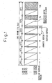
- Figure 1 shows a frame consisting of eight subframes SF0 to SF7.
- the subframe SF0 represents a lowest intensity level and corresponds to a least significant bit b0 in display data.
- the subframe SF7 represents a highest intensity level and corresponds to a most significant bit b7 in the display data.
- Figure 2 shows the ON/OFF states of subframes in frames to display intensity levels 127 and 128.
- the frame to display intensity level 127 turns on the subframes SF0 to SF6 and off the subframe SF7.
- the frame to display intensity level 128 turns off the subframes SF0 to SF6 and on the subframe SF7.
- Japanese Unexamined Patent Publication (Kokai) No. 3-14.5691 arranges the subframes of each frame in order of SF0, SF2, SF4, SF6, SF7, SF5, SF3, and SF1.
- Japanese Unexamined Patent Publication (Kokai) No. 5-1276,12 describes that dividing a frame into subframes sometimes causes rough, low-quality dynamic images, and proposes an improved frame dividing technique.
- This technique employs a unit for doubling a frame frequency if a given frame frequency is less than 70 Hz.
- Each frame under the doubled frame frequency has at least one normal-bit subframe including a highest-intensity-level subframe and at least one under-bit subframe.
- the technique displays a static image with every two frames representing an intensity level, and a dynamic image with every frame representing an intensity level. This technique creates display data for the doubled frames according to input display data.
- Figure 3 shows a first frame displaying intensity level 31 and a second frame displaying intensity level 32 among the frequency-doubled frames.
- subframes 31a and 32a provide an identical intensity level
- subframes 31b and 32b provide another identical intensity level.
- These subframes are normal-bit subframes.
- the other subframes are under-bit subframes.
- each frame consists of six subframes that are arranged in order of SF5, SF4, SF3, SF2, SF1, and SF0.
- Figures 4 to 6 show different types of halftone disturbance according to a prior art and Fig. 7 shows a dark part formed between intensity levels 31 and 32 during a right scroll.
- a vertical blue line is displayed with the subframe SF5 being turned on, and the blue line is scrolled from the right to the left.
- the blue line is scrolled at a speed of a pixel per frame, the human eye sees as if it is smoothly moving even over red and green subpixels that emit no light actually.
- each pixel consists of a red subpixel, a green subpixel, and a blue subpixel.
- the smooth movement is visible even when the blue line is moved at a speed of several pixels per frame. This phenomenon of the human eye seeing a smooth movement is called an "apparent motion" or " ⁇ motion” in psychology.
- the vertical blue line is displayed with the subframes SF5 and SF4 being turned on and is scrolled from the right to the left at a speed of a pixel per frame.
- the human eye sees as if the subframes SF5 and SF4 are spatially separated from each other.
- the subframe SF5 is turned on in a blue subpixel, the human eye sees as if it is moving over red and green subpixels.
- Figures 6 shows a vertical blue line displayed with the subframes SF5 to SF0 being turned on and scrolled from the right to the left at a speed of two pixels per frame. Due to the extended intervals of two pixels, the human eye sees faster movements of the subframes. When the subframe SF4 is turned on about 2 msec after the subframe SF5, the subframe SF5 is ahead of SF4 on the human eye. Namely, the human eye sees the subframes spreading for a distance corresponding to a frame period.
- each frame actually emit light in a single pixel, it appears to the human eye as if they emit light in different pixels when a dynamic image is displayed. In this case, an intensity level assigned to a given frame is not displayed as the sum of the subframes, thereby causing halftone disturbance.
- Figures 7 to 9 show dark and bright parts that appear between specific intensity levels in a single-color halftone image that is being scrolled.
- each frame consists of six subframes. SF5 to SF0 that are arranged in descending order of the intensity levels thereof. A blue halftone image is displayed with the intensity level thereof gradually increasing from the left to the right and is scrolled to the right. A dark part appears between specific intensity levels that involve quite different numbers of ON subframes.
- Such dark part is produced between, for example, intensity levels 31 and 32, 15 and 16, or 7 and 8.
- Fig. 7 the image is moved at a speed of two pixels per frame, and a dark part appears between intensity level 31, which is realized by turning on the subframes SF4 to SF0, and intensity level 32, which is realized by turning on the subframe SF5 only.
- the dark part occurs because the subframes are spatially separated from one another in the human eye.
- the dark part of Fig. 7 extends for one pixel composed of red (R), green (G), and blue (B) subpixels.
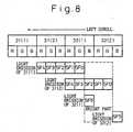
- Figure 8 shows the same image as that of Fig. 7 but scrolled to the left. In this case, a bright part is observed between intensity levels 31 and 32.
- Figure 9 shows an image involving opposite intensity levels to those of Fig. 7 .
- the image is scrolled to the right like Fig. 7 .
- a bright part appears between intensity levels 31 and 32.
- the image when displaying a dynamic image with single color or with the same subframes being turned on in each subpixel of a given pixel, the image may involve a dark or bright part.
- the image When displaying a dynamic image with different subframes being turned on in the subpixels of a given pixel, the image may involve false color contours.
- each frame consists of subframes SF0 to SF7 with the subframe SF0 providing a lowest intensity level and the subframe SF7 providing a highest intensity level.
- Figure 10A shows a dynamic image scrolling from the left to the right at a speed of a pixel per frame
- Fig. 10B shows a dynamic image scrolling from the right to the left at a speed of a pixel per frame.
- an ordinate represents time t
- an abscissa represents spatial positions x.
- Reference marks 1F to 4F represent frames.
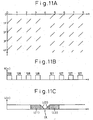
- Figures 11A to 11C correspond to Fig. 10A and show a problem occurring when the image is moved from the left to the right.
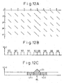
- Figures 12A to 12C correspond to Fig. 10B and show a problem occurring when the image is moved from the right to the left.
- the image of Fig. 10A includes consecutive pixels that display intensity levels 128 and 127.
- the image is moved from the left to the right at a speed of a pixel per frame. Due to the apparent motion, a coordinate origin on the retina of the human eye moves along a dotted line ROR.
- the image of Fig. 10A is observed as shown in Fig. 11A if coordinates on the retina are fixed.
- the image of Fig. 10B includes consecutive pixels that display intensity levels 128 and 127.
- the image is moved from the right to the left at a speed of a pixel per frame.
- a coordinate origin on the retina moves along a dotted line ROL.
- the image of Fig. 10B is observed as shown in Fig. 12A if coordinates on the retina are fixed.
- Intensity level 127 is realized by turning on the subframes SF0 to SF6 and off the subframe SF7.
- Intensity level 128 is realized by turning off the subframes SF0 to SF6 and on the subframe SF7. For the sake of simplicity, each pixel has no area in Figs. 11A and 12A .
- intensity levels K(x) at positions x on the retina have a gap between intensity levels 128 and 127 as shown in Fig. 11B .
- stimulus L(x) on the retina drops to form a valley as shown in Fig. 11C .
- intensity levels K(x) at positions x on the retina are continuous as shown in Fig. 12B
- stimulus L(x) on the retina shows a peak between intensity levels 128 and 127 as shown in Fig. 12C .
- FIGS 13A to 13I explain the method proposed in this related art.
- Figure 13A shows the emission intensity I(t) of a pixel that displays intensity level 127 and then 128.
- An abscissa represents time.
- Frames 1F and 2F display intensity level 127, and frames 3F and 4F display intensity level 128.
- Figure 13B shows stimulus P(t) on the retina of the human eye in response to the emission intensity I(t).
- the stimulus P(t) periodically changes between P1 and P2 while the pixel is displaying intensity level 127.
- the stimulus drops below P2.
- the stimulus again oscillates between P1 and P2.
- Figure 13C shows visual intensity B(t) that is an integral of the stimulus P(t) for an afterimage time. If S1 ⁇ S2, ⁇ S3, no disturbance is observed in the halftone image. The example of Fig. 13C does not satisfy this condition. As a result, a dark part is observed between intensity levels 127 and 128. If ⁇ S is added to S2 to realize S1 ⁇ S2 + ⁇ S ⁇ S3, no disturbance is observed in the halftone image.
- a corrective pulse (equalizing pulse) EP as shown in Fig. 13D.
- Figure 13E shows stimulus P(t) on the retina due to the corrective pulse EP that turns on a corresponding subframe.
- Figure 13F shows visual intensity B(t) due to the corrective pulse EP.
- Figures 13G, 13H, and 13I show emission intensity I(t), stimulus P(t) on the retina, and visual intensity B(t), respectively, due to the corrective pulse EP.
- the corrective pulse EP reduces disturbance in the visual intensity.
- the corrective pulse EP may be negative (EPS) to reduce the intensity level.
- Figure 14 shows a circuit for inserting a corrective pulse for adjusting an intensity level according to the related art.
- the circuit has a frame memory 310 and an addition circuit 400.
- the frame memory provides a delay of a vertical synchronous period.
- the addition circuit 400 has a tester 410 and an adder 420.
- the tester 410 has a comparator 410a and a lookup table 410b, which maybe a ROM.
- the comparator 410a compares each bit in a frame n with a corresponding bit in the next frame n+1.
- the comparator 410a provides +1 for any bit that shows a change from ON to OFF, -1 for any bit that shows a change from OFF to ON; and 0 for any bit that is unchanged.
- the lookup table 410b provides a corrective pulse in response to the output of the comparator 410a.
- This corrective pulse may be positive, negative, or nil.
- the adder 420 adds the corrective pulse to original data 210 and provides corrected display data 220.
- the related art is advantageous in that it realizes a given intensity level on the human eye.
- the total of S2+ ⁇ S is nearly equal to S1 or S3 although there is a temporal fluctuation therein. Accordingly, the halftone image is visible without disturbance if it is seen away from the display.
- the related art is effective to stabilize still and moving images. However, it is unsatisfactory on fast-moving images.
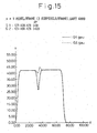
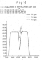
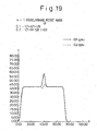
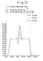
- Figures 15 to 22 show results of simulations of moving an image on a screen at different speeds.
- Figures 15 and 19 move the image leftward and rightward at a pixels pre frame, Figs 16 and 20 at 3 pixels per frame, Figs. 17 and 21 at 4 pixels per frame, and Figs. 18 and 22 at 5 pixels per frame.
- a left half of the displayed image has intensity level 127, and a right half thereof has intensity level 128.
- a continuous line is without a corrective pulse, and a dotted line is with a corrective pulse according to the related art.
- An ordinate represents intensity and an abscissa positions on the retina.
- a dot-dash line is with a corrective pulse according to the present invention.
- Figs. 15 and 19 the image is moved at a slow speed of a pixel per frame. Each pixel consists of three subpixels.
- a positive or negative corrective pulse according to the related art is sufficient to prevent halftone disturbance. If no corrective pulse is applied, negative disturbance of Fig. 15 or positive disturbance of Fig. 19 will occur. The corrective pulses cancel these disturbances.
- Figure 23A corresponds to Fig. 1 and shows a technique of displaying an image with separate addressing and sustain periods.
- Figure 23B shows a technique of displaying an image with distributed addressing and sustain periods.
- Figure 24 shows a display according to the present invention.
- the display 100 is connected to an inserter 200 for inserting a corrective pulse for adjusting an intensity level.
- the display 100 has a display panel 102, an x-decoder 131, an x-driver 132, a y-decoder 141, a y-driver 142, and a controller 105 for controlling the x- and y-drivers 131 and 141.
- a frame of an image is divided into subframes and is displayed on the display panel 102.
- Each subframe is made of an addressing period and a sustain period.
- the display 100 may be a plasma display, a DMD (digital micromirror device), an EL (electro luminescence) panel, or any other display that divides a frame into subframes.
- the inserter 200 is characteristic to the present invention.
- the inserter 200 adds a corrective pulse for adjusting an intensity level to original display data 210 and provides the display 100 with corrected display data 220.
- Embodiments of the present invention allow the total intensity level achieved by corrective pulses applied to pixels to be maintained and corrective pulses to average the intensity levels of the pixels to be individually weighted. Moreover, the halftone disturbance can be minimized without changing brightness.
- Figures 25 to 28B show a method of displaying a halftone image according to an embodiment of the present invention.
- the embodiment adds weighted positive corrective pulses to original display data.
- the embodiment divides each frame of an image into eight subframes SF0 to SF7.
- Fig. 25 an image is moved to the left at a speed of 3 pixels per frame.
- An ordinate represents time t and frames 1F, 2F, 3F, and so on, and an abscissa represents horizontal positions of pixels A, B, C, and so on, on the display panel.
- the display panel is monochrome.
- each pixel consists of red, green, and blue subpixels. The area of each pixel is sufficiently small.
- Each vertical line in Fig. 25 indicates the light emission state of a pixel.
- pixels A to C and P are OFF, pixels D to I display intensity level 127, and pixels J to O display intensity level 128.
- the pixels D to I emit light
- the pixels J to O emit light
- the pixels A to F display intensity level 127
- the pixels G to L display intensity level 128.
- the pixels A to F emit light
- the pixels G to L emit light.
- each stripe consists of six pixels of intensity level 127, and the right half thereof consists of six pixels of intensity level 128.
- the stripes move to the left at three pixels per frame. Although the stripes are displayed.intermittently, the human eye sees that the stripes are smoothly moving, and the center of the retina follows the stripes.
- Figure 26A shows retina positions x on an abscissa.
- the eye follows it. Accordingly, pixels projected on the retina move to the right.
- each pixel projected on the retina moves along an oblique line.
- Intensity level 127 is on the left side
- intensity level 128 is on the right side.
- Figure 26B shows stimulus on the retina.
- the stimulus is calculated by integrating light emission for a frame period of 0.5F to 1.5F. The same is applied to Figs. 27A to 28B .
- a dark part DP appears between intensity levels 127 and 128.
- the pixels G, H, and I change from 127 to 128 in intensity level between the first and second frames, to produce a frame period DD that emits no light. This is the dark part DP.
- Figure 27A shows the related art, which applies a corrective pulse EPA to each of the pixels G, H, and I.
- the corrective pulse EPA may correspond to intensity level 63.
- Figure 27B shows an improvement in the stimulus on the retina due to the corrective pulse EPA on the pixels G, H, and I. Comparison of Figs. 26B and 27B tells the effect of the related art. A dark part in intensity level 127 and a bright part in intensity level 128 cancel each other to make disturbance negligible if the image is seen away from the display panel.
- Figures 28A and 28B show an example of the present invention employing weighted positive corrective pulses.
- a corrective pulse EPA1 corresponding to intensity level 127 is applied to the pixel G, a corrective pulse EPA2 corresponding to intensity level 63 to the pixel H, and a corrective pulse EPA3 corresponding to intensity level 0 to the pixel I.
- Figure 29 shows the corrective pulses of Figs. 28A and 28B overlaid on the image shown in Fig. 25 .
- Figure 30 shows waveforms to realize the light emission of Fig. 29 .
- the corrective pulse EPA1 realizes intensity level 127 by turning on the subframes SF0 to SF6 and is applied to the pixel G when the intensity level thereof changes from 127 to 128.
- the corrective pulse EPA2 realizes intensity level 63 by turning on the subframes SF0 to SF5 and is applied to the pixel H when the intensity level thereof changes from 127 to 128.
- These corrective pulses EPA1 and EPA2 are hatched in Fig. 30 .
- the corrective pulse EPA3 corresponding to intensity level 0 is applied to the pixel I when the intensity level thereof changes from 127 to 128.
- the corrective pulse EPA3 actually does nothing to the pixel I. In this way, the present invention prevents disturbance in the halftone image.
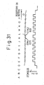
- Figure 31 shows vertically compressed patterns between 0.5F to 1.5F of Figs. 28A and 28B .
- This frame corresponds to any one of frames shown in Figs. 40A to 44 .
- Figures 32A and 32B show weighted corrective pulses according to a modification of the present invention.
- corrective pulses EPA1, EPA2, and EPA3 correspond to intensity levels 95, 95, and 0, respectively, and are applied to the pixels G, H, and I, respectively.
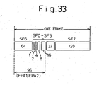
- the subframes are arranged in order of SF6, SF0 to SF5, and SF7. Accordingly, the intensity level 95 of each of the corrective pulses EPA1 and EPA2 is realized by turning on the subframes SF5 and SF0 to SF4. In this way, the subframes may be rearranged according to intensity levels achieved with weighted corrective pulses, which are selected according to given halftones and an image moving speed.
- Figures 34A to 37B show a method of displaying a halftone image according to another embodiment of the present invention. This embodiment employs weighted negative corrective pulses.
- Figures 34A to 36B correspond to Figs. 26A to 28B
- Figs. 37A and 37B correspond to Figs. 32A and 32B .
- Figs. 34A to 37B the halftone image is moving to the left at 3 pixels per frame.
- An ordinate represents time t and frames 1F, 2F, 3F, and the like, and an abscissa represents positions x on the retina of the human eye.
- pixels A to C and P are OFF, pixels D to I display intensity level 128, and pixels J to 0 display intensity level 127.
- the pixels J to O are ON, and in the second half thereof, the pixels D to I are ON.
- the pixels A to F display intensity level 128, and the pixels G to L display intensity level 127. Accordingly, in the first half of the second frame 2F, the pixels G to L are ON, and in the second half thereof, the pixels A to F are ON. These are repeated. If every horizontal line on the display panel displays the pattern of Fig. 34A , the eye will see stripes.
- each stripe consists of six pixels displaying intensity level 128, and the right half thereof consists of six pixels displaying intensity level 127.
- the stripes move to the left at 3 pixels per frame. Although the pixels are turned on discretely in terms of time, the human eye sees that the stripes are moving smoothly, and the center of the retina follows the stripes. When the stripes move to the left, the eye follows them, and therefore, the pixels projected on the retina move to the right.
- the pixels G, H, and I display intensity level 128 in the first frame 1F and then intensity level 127 in the second frame 2F. This means that the pixels G, H, and I are continuously ON in a frame period from 0.5F to 1.5F.
- Figure 34B shows stimulus on the retina integrated for a frame period of 0.5F to 1.5F. The same is applied to Figs. 35A to 37B .
- a bright part BP appears between intensity levels 128 and 127.
- the pixels G, H, and I change their intensity level from 128 to 127 between the frames 1F and 2F, the bright part BP is produced for a frame period.
- To cancel the bright part BP it is necessary to apply negative corrective pulses, contrary to the positive corrective pulses of Figs. 26A and 26B .
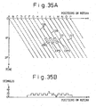
- Figure 35A shows the related art of Japanese Patent Application No. 8-198916 , which applies a negative corrective pulse EPS to each of the pixels G, H, and I.
- the corrective pulse EPS corresponds to intensity level 63.
- FIG. 15 to 18 show an image having a left half of intensity level 127 and a right half of intensity level 128 moving to the left
- Figs. 19 to 22 show the same image moving to the right
- Figs. 19 to 22 show an image having a left half of intensity level 128 and a right half of intensity level 127 moving to the left.
- Figures 36A and 36B show an example of the present invention employing weighted negative corrective pulses.
- a corrective pulse EPS1 corresponding to intensity level -127 is applied to the pixel G, a corrective pulse EPS2 corresponding to intensity level - 63 to the pixel H, and a corrective pulse EPS3 corresponding to intensity level 0 to the pixel I.
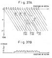
- Figures 37A and 37B show a modification of the embodiment of Figs. 36A and 36B .
- This embodiment applies corrective pulses EPS1, EPS2, and EPS3 corresponding to intensity levels -95, -95, and 0, respectively to the pixels G, H, and I, respectively.
- each pixel takes any one of four cases listed in Table 1: Table 1 Case Move Intensity levels Disturbance Corrective pulses Weighting adjacent to C11 Left 127 - 128 Dark +127, +63, 0 127 C12 Right 127 - 128 Bright 0, -63, -127 128 C13 Left 128 - 127 Bright -127, -63, 0 128 C14 Right 128 - 127 Dark 0, +63, +127 127
- the stripe moves to the left at 3 pixels per frame.
- the left half of the stripe has intensity level 127 and the right half thereof has intensity level 128. If the human eye follows the moving stripe, a dark part will appear between the intensity levels.
- corrective pulses EPA1, EPA2, and EPA3 corresponding to intensity levels +127, +63, and 0 are applied to the pixels that display intensity level 128 so that the pixel beside a pixel of intensity level 127 may receive the corrective pulse EPA1, the second nearest pixel to the intensity-level-127 pixel may receive the corrective pulse EPA2, and the third nearest pixel to the intensity-level-127 pixel may receive the corrective pulse EPA3.
- the stripe image moves to the left at 3 pixels per frame.
- the left half of the stripe has intensity level 128 and the right half thereof has intensity level 127. If the human eye follows the stripe, a bright part appears between the intensity levels.
- corrective pulses EPS1, EPS2, and EPS3 corresponding to intensity levels -127, -63, and 0 are applied to pixels that display intensity level 127 so that the pixel beside a pixel of intensity level 128 may receive the corrective pulse EPA1, the second nearest pixel to the intensity-level-128 pixel may receive the corrective pulse EPA2, and the third nearest pixel to the intensity-level-128 pixel may receive the corrective pulse EPA3.
- the cases C12 and C14 will be understood from the cases C13 and C11.
- the intensity level of pixels changes from 127 to 128 to produce a dark part between the intensity levels.
- positive corrective pulses EPA1, EPA2, and EPA3 are used.
- the absolute values of the corrective pulses are, for example, 0, 63, and 127.
- the corrective pulse having the largest absolute value is applied to a pixel of intensity level 128 beside a pixel whose intensity level is unchanged at 127.
- the intensity level of pixels changes from 128 to 127 to produce a bright part between the intensity levels.
- negative corrective pulses EPS1, EPS2, and EPS3 are used.
- the absolute values of the corrective pulses are 0, 63, and 127.
- the corrective pulse having the largest absolute value is applied to a pixel of intensity level 127 beside a pixel whose intensity level is unchanged at 128.
- the image is moved at 3 pixels per frame, and the consecutive three pixels G, H, and I simultaneously change their intensity level from 127 to 128. Accordingly, the three weighted corrective pulses EPA1, EPA2, and EPA3 are applied to the pixels G, H, and I. If the image is moved at n pixels per frame, n corrective pulses will be applied to n pixels.
- a nearest integer is used. For example, if the image is moved at 3.5 pixels per frame, the image is moved by 3 pixels in the first frame, by 4 pixels in the second frame, and by 3 pixels in the third frame, so that the image is moved at an average speed of 3.5 pixels per frame.
- a television signal sampling technique automatically carries out such averaging.
- Table 3 shows weighted corrective pulses for different horizontal speeds ranging from 1 to 7 pixels per frame.
- Figs. 28A and 28B three consecutive pixels display the same intensity level. This corresponds to "300" in Table 3. If the intensity level of the pixels changes from 127 to 128, three positive corrective pulses (+127, +63, 0; 2/1/0) are selected and applied to the pixels G, H, and I. If the intensity level of the three pixels changes from 128 to 127 as shown in Figs. 36A and 36B , three negative corrective pulses (-127, -63, 0) are selected and applied to the pixels G,H, and I. In Table 3, the symbols represent corrective pulses.
- the symbol “2" corresponds to a corrective pulse of intensity level 127
- the symbol “1.5” corresponds to a corrective pulse of intensity level 95
- the symbol “1” corresponds to a corrective pulse of intensity level 63
- the symbol "0" corresponds to a corrective pulse of intensity level 0.
- a pulse set "302" in Table 3 is a modification of a pulse set "301." If the intensity level of the pixels G, H, and I changes from 127 to 128, positive corrective pulses (+95, +95, 0; 1.5/1.5/0) are selected and applied to the pixels as shown in Figs. 32A and 32B . If the intensity level of the pixels changes from 128 to 127, negative corrective pulses (-95, -95, 0) are selected and applied to the pixels as shown in Figs. 37A and 37B . When the image is moved at any one of speeds of 4 to 7 pixels per frame, corrective pulses are selected in Table 3 and are applied to corresponding pixels, to reduce disturbance. The weight of each corrective pulse is not uniquely determined. An optimum weight must be selected in consideration of subframes, etc., as explained with reference to Fig. 33 .
- the present invention removes false contours from an image moving on a display panel, thereby improving the quality of the image.
- the influence of the corrective pulses on a still image will be examined.
- the present invention applies weighted corrective pulses to pixels even when displaying a full-screen halftone still image involving gradually changing intensity levels. It is preferable, however, to apply unweighted corrective pulses to the pixels if the target is a still image because there is no movement on the retina with respect to the still image.
- the present invention inserts weighted corrective pulses to both still and moving images only momentarily when the intensity level of the image changes around a specific value.
- the positions of pixels to which the corrective pulses are applied move on the retina, and therefore, there will be no problem. False contours are visible when they appear at fixed positions on the retina. If they move on the retina, they are not visible. Accordingly, the weighted corrective pulses cause no problem on the still image.
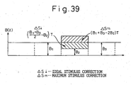
- Figures 38 and 39 relate to a method of determining the corrective pulse which is now the subject of EP04028217.0 , which was divided out of the present application.
- Figures 38A to 39 explain corrective pulses applied to original display data in which Figs. 38A to 38C show an ideal corrective pulse, and Fig. 39 shows an allowable range of a corrective pulse.
- An image on the display is moved at a speed V, which is equal to or larger than 2 pixels per frame. Namely, at least two pixels each involving an intensity level change of Fig. 38A horizontally exist.
- Figure 38A corresponds to Fig. 13A
- Fig. 38B corresponds to Fig. 13C .
- an area 11 shows intensity level 127 with bits b0 to b6 being ON
- an area 13 shows intensity level 128 with a bit b7 being ON
- an area 12 shows a change in intensity level from 127 to 128.
- Figure 38C shows averages B 1 , B 2 , and B 3 calculated by dividing the stimuli B(t) of the areas 11, 12, and 13 of Fig. 38B by a frame period T.
- the stimulus ⁇ S on the retina due to a corrective pulse must satisfy any one of the following expressions: B 1 ⁇ T ⁇ B 2 ⁇ T + ⁇ S ⁇ B 3 ⁇ T B 1 ⁇ T ⁇ B 2 ⁇ T + ⁇ S ⁇ B 3 ⁇ T
- the expression (1) is ideal when the intensity level increases, and the expression (2) is ideal when the intensity level decreases.
- Figs. 27A, 27B , 35A, and 35B applies an identical corrective pulse to each of target pixels (G, H, I).
- the present invention applies weighted corrective pulses corresponding to, for example, intensity levels 127, 63, and 0 to the target pixels (G, H, I), respectively.
- the total intensity level of corrective pulses applied to a target area may be fixed. Namely, the total intensity level of the weighted corrective pulses is equal to that of the related art of Figs. 27A and 27B .
- the sum of stimulus due to the corrective pulses is n ⁇ S. This, however, is not always equal to a calculated value. If the total is nearly equal to the calculated one, the same effect is secured.
- the total intensity level of corrective pulses may be adjusted according to an arrangement of subframes, to suppress disturbance more effectively.
- the stimulus sum ⁇ S on the retina due to the corrective pulses may vary within the range of 0 to a maximum ⁇ Sm, which double the ideal stimulus ⁇ Si. If ⁇ S is out of this range, it will increase the disturbance.
- the stimulus ⁇ S on the retina realized by corrective pulses must satisfy the following if B 2 ⁇ (B 1 + B 3 )/2: 0 ⁇ ⁇ S ⁇ ( B 1 + B 3 - 2 ⁇ B 2 ) T If B 2 ⁇ (B 1 + B 3 ) /2, the stimulus ⁇ S must satisfy the following: 0 ⁇ ⁇ S ⁇ ( B 1 + B 3 - 2 ⁇ B 2 ) T
- Pixels on a display panel are arranged in a square matrix, and the image is moved at 3 pixels per frame toward a lower left part along diagonal lines inclined at 45 degrees.
- Figures 40A to 43 show a method of displaying such a diagonally moving halftone image according to still another embodiment of the present invention.
- Figure 40A shows two-dimensional coordinates fixed on the retina of the human eye.
- the image projected on the retina moves at 3 pixels per frame in an upper right direction along diagonal lines inclined at 45 degrees.
- the left side of a straight line AA has intensity level 127 with bits b0 to b6 being ON, and the right side thereof has intensity level 128 with a bit b7 being ON.
- Figure 40B shows stimulus L on the retina for a pixel line CC.
- each segment indicates light emission at each pixel in each frame.
- the segments correspond to the vertically compressed light emission patterns of Fig. 31 .
- Black and white dots in Fig. 40A represent pixel positions at time 0.
- Pixels P1, P2, P3 display intensity level 127 with bits b0 to b6 being ON to turn on the subframes SF0 to SF6.
- pixels P4, P5, and P6 display intensity level 128 with a bit b7 being ON to turn on the subframe SF7.
- the pixels P4, P5, and P6 display intensity level 127. This means that, on the retina, the pixels P1 to P3 move to the positions of the pixels P4 to P6. As a result, a dark part DD is observed as shown in Figs. 40A and 40B .
- Figure 41 shows corrective pulses applied according to the present invention.
- the corrective pulse EPA1 corresponding to intensity level +127, EPA2 corresponding to intensity level +63, and EPA3 corresponding to intensity level 0 are applied to the pixels P1 to P3.
- Each parenthesized numeral represents a pixel to which a corrective pulse is applied.
- (2) is a pixel such as P1 to which the corrective pulse EPA1 of intensity level +127 is applied
- (1) is a pixel such as P2 to which the corrective pulse EPA2 of intensity level +63 is applied
- (0) is a pixel such as P3 to which the corrective pulse EPA3 of intensity level 0 is applied.
- Figure 42 shows an image diagonally moving at 2 pixels per frame. In this case, corrective pulses of intensity levels +127 and 0 are applied to corresponding pixels.
- Figure 43 shows a modification of Fig. 40A .
- the left side of a straight line AA has intensity level 128 and the right side thereof has intensity level 127.
- This modification corresponds to Figs. 36A and 36B .
- Fig. 43 shows only a row of pixels, there are actually many rows of pixels as shown in Fig. 40A .
- black and white dots represent pixel positions at time 0.
- Reference mark (/2) indicates a pixel such as P1 to which a corrective pulse EPS1 corresponding to intensity level -127 is applied
- (/1) indicates a pixel such as P2 to which a corrective pulse EPS2 corresponding to intensity level -63 is applied
- (0) indicates a pixel such as P3 to which a corrective pulse EPS3 corresponding to intensity level 0 is applied.
- the human eye senses the pixels P1 to P3 moving to the positions of the pixels P4 to P6. Accordingly, the corrective pulses EPS1 to EPS3 are applied to the pixels P1 to P3, respectively.
- the corrective pulses EPS1 and EPS2 cancel original intensity levels as indicated with dotted lines in Fig. 43 , to thereby eliminate a bright part BB appearing between the intensity levels 128 and 127.
- the speed and direction of an image to be displayed are unknown in advance.
- a method of providing weighted corrective pulses for this kind of image will be explained. The method generalizes the moving speed and direction of an image to be displayed and applies weighted corrective pulses to the image.
- the number of consecutive pixels having the same ON/OFF states in the subframe bits b5, b6, and b7 is counted vertically and horizontally, and a smaller one of them is selected.
- Table 3 is referred to, to determine weighted corrective pulses according to the selected number, and the corrective pulses are added to original display data.
- a moving speed expressed in pixels per frame is equal to the number of pixels that show an identical intensity change.
- the corrective pulses of Fig. 41 for the diagonally moving image will be determined according to a technique shown in Table 4.
- Table 4 1 The intensity levels of pixels in a frame n and those in the next frame n+1 are compared with each other. If the seventh bit for a given pixel is OFF in both the frames n and n+1 to indicate intensity level 127, "a" is stored for the pixel in a RAM. If the seventh bit for the pixel is OFF in the frame n to indicate intensity level 127 and ON in the frame n+1 to indicate intensity level 128, "b" is stored for the pixel in the RAM.
- Fig. 40A there are six horizontal and vertical pixels that simultaneously change their intensity level from 127 to 128. Accordingly, "303" in Table 3 for a moving speed of 6 pixels per frame is referred to and +127, +127, +127, 0, 0, and 0, or +127, +127, +63, +63, 0, and 0 are selected for weighted corrective pulses. Any pixel provided with the corrective pulse of +127 is represented with (2), any pixel provided with the corrective pulse of +63 is represented with (1), and any pixel provided with the corrective pulse of 0 is represented with (0).
- the corrective pulses of +127, +127, +127, 0, 0, and 0 are selected, they are applied as shown in Fig. 44 . Although they are slightly different from the example of Fig. 41 , an average of two lines moving diagonally is equal to that of Fig. 41 . If the corrective pulses of +127, +127, +63, +63, 0, and 0 are selected, they are applied as shown in Fig. 41 .
- Table 4 is applicable to select weighted corrective pulses for the diagonally moving image of Fig. 42 .
- Figures 45 and 46 show an image moving diagonally and involving an intensity level change in a different direction.
- the image changes its intensity level along a straight line AA and moves toward a lower left part along a diagonal line inclined at 45 degrees. Accordingly, each pixel moves on the retina toward an upper right part along a diagonal line of 45 degrees.
- ( 2 ), ( 1 ), and (0) are pixels receiving corrective pulses corresponding to intensity levels +127, +63, and 0, respectively.
- the number of pixels having the same ON/OFF states in the subframe bits b7, b6, and b5 is counted in a horizontal direction HH and in a vertical direction VV.
- Fig. 45 there are three pixels in the horizontal direction HH, and six pixels in the vertical direction VV. Accordingly, the smaller number "3" is selected to refer to Table 3 to select weighted corrective pulses.
- the reason why the subframe bits b7, b6, and b5, in particular, b7 and b6 are checked is because they greatly influence halftone disturbance.
- the smaller number "3" guides to "300" in Table 3, and 2/1/0 and 1.5/1.5/0 will be selected from the table. Namely, weighted corrective pulses corresponding to intensity levels 127, 63, and 0, or those corresponding to intensity levels 95, 95, and 0 will be selected. In Fig. 45 , the corrective pulses of 127, 63, and 0 (2/1/0) are selected and added to original display data.
- Figure 46 shows weighted pulses selected according to Table 4 for the pixels of Fig. 45 . There is a slight difference between Figs. 45 and 46 . However, averages of two lines diagonally moving of the two examples are substantially equal to each other.
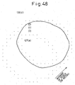
- Figures 47 to 50 show a circular image moving diagonally according to an embodiment of the present invention.
- Fig. 47 the circular image moves toward a lower left part along a diagonal line inclined at 45 degrees.
- the inside of the image has intensity level 127, and the outside thereof has intensity level 128.
- Pixels projected on the retina move toward an upper right part at an angle of 45 degrees.
- Reference marks (2), (1), and (0) are pixels receiving corrective pulses of intensity levels, +127, +63, and 0, respectively.
- Figure 48 shows the movement of the image.
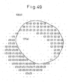
- Figure 49 shows weighted corrective pulses selected for the image of Fig. 47 from an upper row of Table 3.
- the corrective pulses of Fig. 49 are substantially equal to those of Fig. 47 .
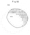
- Figure 50 shows weighted corrective pulses selected for the image of Fig. 47 from a lower row of Table 3. They are substantially equal to those of Fig. 47 .
- Figure 51 shows an image moving in a non-diagonal direction and involving an intensity level change in the moving direction.
- Fig. 51 Pixels of Fig. 51 are provided with weighted corrective pulses according to Table 4 of the present invention.
- the corrective pulses of Fig. 51 resemble those of Fig. 41 .
- the method of Table 4 of the present invention will be explained in detail with reference to Figs. 52 to 60B .
- the method is achievable with circuits or with a program executed by a computer.
- the program consists of routines to be explained below with reference to flowcharts.
- the program is stored in a flexible disk, a hard disk, a CDROM, an MO disk, or any type of nonvolatile memory and is distributed.
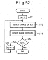
- Figure 52 is a flowchart showing a main routine for carrying out a method according to an embodiment of the present invention.
- Step ST2 carries out a routine of detecting a change in each bit b7 in frames n and n+1. Resultant data of step ST2 is stored in a memory. Step ST3 carries out a routine of correcting false contours.
- Figure 53 shows the details of step ST2 of Fig. 52 .
- the variables i and j are the coordinates of a given pixel on the screen.
- the horizontal coordinate i ranges from 0 to k
- the vertical coordinate j ranges from 0 to m. Namely, the screen has a matrix of k+1 horizontal pixels and m+1 vertical pixels.
- Step ST23 reads, for a pixel (0, 0), a bit b7 (n) from a frame n and a bit b7 (n+1) from the next frame n+1.
- Step ST24 compares (confirms) the bits read in step ST23 with each other, finds a value yij from Table 5, and stores_ the value yij in the memory.
- Table 5 Item (b7 (n) , b7 (n+1) yij Remarks 1 (0, 0) 00 (a) No carry-up or carry-down 2 (0, 1) 01 (b) Carry-up 3 (1, 0) 10 (c) Carry-down 4 (1, 1) 11 (d) No carry-up or carry-down
- Figure 54 is a flowchart showing the details of step ST3 of Fig. 52 . Steps ST35 and ST36 will be explained later with reference to Figs. 55 to 57 and 58 to 60B .
- Step ST33 reads y 00 for a pixel (0, 0) and checks to see if y 00 is b or c. Namely, it checks to see if y 00 specifies carry-up or carry-down. If y 00 is b or c, step ST34 is carried out, and if not, step ST37 is carried out.
- Step ST34 checks the pixel (0, 0) to see if it is provided with a corrective pulse due to the processing of another pixel. If the pixel is provided with the corrective pulse, step ST37 is carried out, and if not, step ST35 detects a movement. Thereafter, step ST36 applies a corrective pulse to the pixel in question, and step ST37 is carried out.
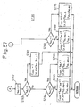
- Figures 55 to 57 show the details of step ST35 of Fig. 54 , in which Fig. 55 shows a subroutine of detecting a horizontal movement, and Figs. 56 and 57 are subroutines of detecting a vertical movement. These subroutines take place when carry-up or carry-down is detected in a given pixel (i, j), i.e., if yij is b or c.
- Step ST412 checks to see if i ⁇ 0 to determine whether or not the present pixel is out of the screen. If i ⁇ 0, step ST415 is carried out, and if not, step ST413 is carried out.
- Step ST413 compares the status yiYs of the present pixel with the status yXsYs of the start pixel. If the statuses are different from each other, step ST414 is carried out, and if they are equal to each other, step ST411 is repeated. These steps are repeated until a different status is found, or until an end of the screen is detected.
- steps ST48 to ST52 calculate a horizontal movement and the statuses of two pixels that sandwich the consecutive pixels.
- step ST53 of Fig. 56 is carried out.
- Step ST54 checks to see if j ⁇ 0 to determine whether or not the present pixel is out of the screen. If not j ⁇ 0, step ST57 is carried out, and if j ⁇ 0, step ST55 is carried out.
- Step ST55 compares the status Y Xsj of the present pixel with the status Y XsYs of the start pixel. If they differ from each other, step ST56 is carried out, and if they are equal to each other, step ST53 is repeated. These steps are repeated until a different status is detected, or until an end of the screen is detected.
- Step ST60 checks to see if j > m to determine whether or not the present pixel is out of the boundary m of the screen. If j > m, step ST68 of Fig. 57 is carried out, and if not step ST61 is carried out. Step ST61 compares the status Y Xsj of the present pixel with the status Y XsYs of the start pixel. If they differ from each other, step ST62 of Fig. 57 is carried out, and if they are equal to each other, step ST59 is repeated. These steps are repeated until a different status is detected, or until a vertical end of the screen is detected.
- Figures 58 to 60B show the details of step ST36 of Fig. 54 of applying a corrective pulse.
- step ST71 checks a condition 1 to determine whether or not the horizontal adjacent pixels ( ⁇ , ⁇ ) that sandwich the horizontal consecutive pixels are (a, d) or (d, a). If the condition 1 is satisfied, step ST72 is carried out, and if not, step ST76 is carried out.
- Step ST72 checks a condition 2 to determine whether or not the vertical adjacent pixels ( ⁇ , ⁇ ) that sandwich the vertical consecutive pixels are (a, d) or (d, a). If the condition 2 is satisfied, step ST73 is carried out, and if not, step ST74 is carried out. Step ST73 checks a condition 3 to determine if C XsYs ⁇ B XsYs , where B XsYs and C XsYs are horizontal and vertical movements. If C XsYs ⁇ B XsYs , step ST74 is carried out, and if not, step ST75 is carried out.
- Step ST76 checks the condition 2. If the condition 2 is satisfied, step ST75 is carried out, and if not, step ST77 is carried out. Step ST77 checks the condition 3. If the condition 3 is met, step ST78 is carried out, and if not, step ST79 is carried out.
- step ST80 refers to Table 3 to select a row corresponding to the movement V XsYs .
- Step ST81 selects one of positive and negative corrective pulse sets according to the status of Y XsYs .
- Step ST82 determines a weighting direction of the corrective pulses according to the adjacent pixels ( ⁇ , ⁇ ).
- Step ST83 sequentially applies the corrective pulses to the section sandwiched between the adjacent pixels ( ⁇ , ⁇ ). This completes step ST36 of Fig. 54 , and step ST37 of Fig. 54 is carried out.
- Step ST84 looks up Table 3 and selects a corrective pulse similar to the related art ( Figs. 27A, 27B , 35A, and 35B ).
- Step ST85 sequentially applies the corrective pulse to the section (area) sandwiched between the adjacent pixels ( ⁇ , ⁇ ). This completes step ST36 of Fig. 54 , and step ST37 of Fig. 54 is carried out.
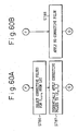
- Figures 60A and 60B show modifications of the processes between F and G of Figs. 58 and 59 .
- Steps ST77 to ST79, ST84, and ST85 of Figs. 58 and 59 correspond to steps ST86 and ST87 of Fig. 60A , or step ST88 of Fig. 60B .
- step ST86 is carried out instead of step ST77.
- Step ST86 looks up Table 3 and selects a corrective pulse similar to the related art ( Figs. 27A, 27B , 35A, and 35B ) according to the start pixel Y XsYs .
- Step ST87 applies the corrective pulse only to the coordinates (Xs, Ys). This completes step ST36 of Fig. 54 , and step ST37 of Fig. 54 is carried out.
- step ST76 determines that the vertical adjacent pixels ( ⁇ , ⁇ ) are not (a, d) or (d, a)
- step ST88 is carried out instead of ST77.
- Step ST88 applies no corrective pulse. This completes step ST36 of Fig. 54 , and step ST37 of Fig. 54 is carried out.
- the method is applicable to images of various moving speeds and directions and, in particular, to halftone images moving at a high speed, e.g., 5 pixels per frame or faster. It is thus possible to reduce disturbance and suppress or eliminate false contours in halftone images.
- Embodiments of the present invention can be implemented not only in gas discharge panels such as plasma display panels but also in other display panels such as DMDs and EL panels that divide a frame of an image into subframes.
- corrective pulses can be applied to pixels that turn on and off synchronously in consecutive frames. Disturbance in halftone images can be reduced and false contours of the images suppressed or eliminated even if the images are moving at a high speed.
Landscapes
- Engineering & Computer Science (AREA)
- Physics & Mathematics (AREA)
- Computer Hardware Design (AREA)
- General Physics & Mathematics (AREA)
- Theoretical Computer Science (AREA)
- Control Of Indicators Other Than Cathode Ray Tubes (AREA)
- Liquid Crystal Display Device Control (AREA)
- Control Of Gas Discharge Display Tubes (AREA)
Description
- The present invention relates to a method of and an apparatus for displaying halftone images in frames each divided into subframes, and more particularly, to a method of and an apparatus for displaying halftone images on a gas discharge display panel without halftone disturbance or false color contours.
- Recently, in order to meet a demand for large thin display units, matrix display panels that display images based on digital signals have been developed. The matrix display panels include gas discharge panels, DMDs (digital micromirror devices), EL (electro luminescence) display panels, fluorescent display panels, and liquid crystal display panels. Among them, the gas discharge panels such as plasma display panels are considered to be most advantageous for direct-view large HDTV (high-quality television) displays because they are simple and easy to form as a large screen, emit light by themselves, provide high display quality, and achieve high-speed response.
- A memory-type gas discharge panel displays a halftone image in frames, and the frames are generated at a frequency of, for example, 60 Hz, and each frame consists of N subframes to provide
intensity levels 2° to 2N-1. The subframes of each frame are turned on/off, and the human eye sees the sum of the intensity levels of the ON subframes as the intensity level of the frame due to the persistence characteristic of the human eye. The number of intensity levels realized in each frame with combinations of the subframes is 2N. - If frames that represent similar intensity levels with quite different combinations of ON subframes alternate, flicker will occur to deteriorate display quality. Further, although the subframes of each frame actually emit light from a single pixel, to the human eye it appears as if they emit light from different pixels when a dynamic image is displayed. In this case, an intensity level assigned to a given frame is not displaced as the sum of the subframe, thereby causing halftone disturbance.
- By the way, in the related art, a method of, and an apparatus for, displaying halftone images by adding a corrective pulse that turns on or off a corresponding subframe to adjust an intensity level is proposed. This related art is advantageous in that it realizes a given intensity level on the human eye, and thus the halftone image is visible without disturbance if it is seen away from the display. Namely, the related art is effective to stabilize still and moving images. However, it is unsatisfactory on fast-moving images.
- The prior and related arts will be described in detailed later with reference to the accompanying drawings.
- XP000729547 "An equalising pulse technique for improving the grey scale capabilities of plasma displays", K. Toda et al, Euro Display '96, 1 october 1996, and
EP-A-0822536 disclose a method of displaying a dynamic halftone image on a display panel comprising pixels by dividing each frame of the image into subframes and by turning on and off the subframes, comprising the steps of: finding a plurality of pixels that simultaneously display a specific intensity level in a frame and another specific intensity level in a next frame; selecting corrective pulses, which turn on/off corresponding subframes to enable/disable corresponding intensity levels; and adjusting original display signals for the found pixels according to the corrective pulses, respectively. - According to a first aspect of the present invention, there is provided a method of displaying a dynamic halftone image on a display panel comprising pixels by dividing each frame of the image into subframes and by turning on and off the subframes, comprising the steps of: comparing original display signals of two consecutive frames in order to find continuous groups of pixels in a horizontal line and continuous groups of pixels in a vertical line, in each of which pixel groups the pixels simultaneously display a first.specific intensity level in one frame and a second, different specific intensity level in the next frame; counting the number of pixels in each of the two pixel groups found in the comparing step; determining the pixel group to which corrective pulses are to be added by selecting the one of the two pixel groups for which the counted number is smaller; detecting the respective emission statuses of pixels adjacent on both sides of the said selected pixel group in the said two frames; selecting corrective pulses to be applied to the pixels of the selected pixel group to turn on/off corresponding subframes to enable/disable corresponding intensity levels, the said corrective pulses being selected according to the said counted number of pixels of that pixel group and said detected emission statuses so as to minimise the unevenness of brightness due to change between said first and second specific intensity levels; and adjusting the original display signals of the found pixels according to the said selected corrective pulses.
- According to a second aspect of the present invention, there is provided a display apparatus for displaying a dynamic halftone image on a display panel comprising pixels by dividing each frame of the image into subframes and by turning on and off the subframes, comprising: comparing means for comparing original display signals of two consecutive frames in order to find continuous groups of pixels in a horizontal line and continuous groups of pixels in a vertical line, in each of which pixel groups the pixels simultaneously display a first specific intensity level in one frame and a second, different specific intensity level in the next frame; counting means for counting the number of pixels in each of the two pixel groups found by the comparing means; determining means for determining the pixel group to which corrective pulses are to be added, by selecting the one of the two pixel groups for which the counted number is smaller; detecting means for detecting the respective emission statuses of pixels adjacent on both sides of the said selected pixel group in the said two frames; selecting means for selecting corrective pulses to be applied to the pixels of the selected pixel group to turn on/off corresponding subframes to enable/disable corresponding intensity levels, the said corrective pulses being selected according to the said counted number of pixels of that pixel group and said detected emission statuses so as to minimise the unevenness of brightness due to change between the said first and second specific intensity levels; and adjusting means for adjusting the original display signals of the found pixels according to the said selected corrective pulses.
- Preferred embodiments of the present invention thus allow fast-moving halftone images to be displayed on a screen without halftone disturbance or false color contours.
- For a better understanding of the invention, and to show how the same may be carried into effect, reference will now be made, by way of example, to the accompanying drawings, in which:-
-
Fig. 1 shows a frame consisting of eight subframes; -
Fig. 2 shows the ON/OFF states of subframes in two frames to displayintensity levels -
Fig. 3 shows a first frame to displayintensity level 31 and a second frame to displayintensity level 32 among frequency-doubled frames according to a prior art; -
Fig. 4 shows an example of halftone disturbance according to the prior art; -
Fig. 5 shows another example of halftone disturbance according to the prior art; -
Fig. 6 shows still another example of halftone disturbance according to the prior art; -
Fig. 7 shows a dark part appearing betweenintensity levels -
Fig. 8 shows a bright part appearing betweenintensity levels -
Fig. 9 shows a bright part appearing betweenintensity levels -
Figs. 10A and 10B show a halftone image under scrolling; -
Figs. 11A to 11C show a problem occurring in the halftone image ofFig. 10A ; -
Figs. 12A to 12C show a problem occurring in the halftone image ofFig. 10B ; -
Figs. 13A to 13I show a method of displaying a halftone image according to a related art; -
Fig. 14 shows a circuit for inserting a corrective pulse for adjusting an intensity level according to the related art; -
Fig. 15 shows simulation results of moving an image leftward at 1 pixel per frame with and without a correction based on the related art; -
Fig. 16 shows simulation results of moving an image leftward at 3 pixels per frame with and without corrections based on the related art and an embodiment of the present invention; -
Fig. 17 shows simulation results of moving an image leftward at 4 pixels per frame with and without corrections based on the related art and an embodiment of the present invention; -
Fig. 18 shows simulation results of moving an image leftward at 5 pixels per frame with and without corrections based on the related art and an embodiment of the present invention; -
Fig. 19 shows simulation results of moving an image rightward at 1 pixel per frame with and without a correction based on the related art; -
Fig. 20 shows simulation results of moving an image rightward at 3 pixels per frame with and without corrections based on the related art and an embodiment of the present invention; -
Fig. 21 shows simulation results of moving an image rightward at 4 pixels per frame with and without corrections based on the related art and an embodiment of the present invention; -
Fig. 22 shows simulation results of moving an image rightward at 5 pixels per frame with and without corrections based on the related art and an embodiment of the present invention; -
Fig. 23A shows a technique of displaying an image with separate addressing and sustain periods; -
Fig. 23B shows a technique of displaying an image with distributed addressing and sustain periods; -
Fig. 24 shows a display according to an embodiment of the present invention; -
Fig. 25 shows a halftone image on a display panel; -
Figs. 26A and 26B show the image ofFig. 25 projected on the retina of a human eye without correction; -
Figs. 27A and 27B show the image ofFig; 25 projected on the retina and corrected according to the related art; -
Figs. 28A and 28B show the image ofFig. 25 projected on the retina and corrected according to an embodiment of the present invention; -
Fig. 29 shows the image ofFig. 25 corrected according to an embodiment of the present invention; -
Fig. 30 shows waveforms to realize the light emission patterns ofFig. 29 ; -
Fig. 31 shows the patterns ofFig. 28A vertically compressed between 0.5F and 1.5F; -
Figs. 32A and 32B show the image ofFig. 25 projected on the retina and corrected according to an embodiment of the present invention; -
Fig. 33 shows rearranged subframes according to an embodiment of the present invention; -
Figs. 34A and 34B show an image on the retina without correction; -
Figs. 35A and 35B show the image ofFigs. 34A and 34B corrected according to the related art; -
Figs. 36A to 37B show the image ofFigs. 34A and 34B corrected according to an embodiment of the present invention; -
Figs. 38A to 38C explain a modified corrective pulse applied to original display data; -
Fig. 39 explains the corrective pulse ofFig. 38 ; -
Figs. 40A and 40B show an image that diagonally moves in an intensity level changing direction; -
Figs. 41 to 44 show the diagonally moving image corrected according to an embodiment of the present invention; -
Figs. 45 and46 show images diagonally moving in a different direction from an intensity level changing direction and corrected according to an embodiment of the present invention; -
Figs. 47 to 50 show a diagonally moving circular image corrected according to an embodiment of the present invention; -
Fig. 51 shows an image moving in an optional direction and corrected according to an embodiment of the present invention; -
Fig. 52 is a flowchart showing the main routine of a method of displaying a halftone image according to an embodiment of the present invention; -
Fig. 53 is a flowchart showing a bit change detecting process of the main routine; -
Fig. 54 is a flowchart showing a false contour removing process of the main routine; -
Figs. 55 to 57 are flowcharts showing a movement detecting process included in the false contour removing process; -
Figs. 58 and59 are flowcharts showing a corrective pulse applying process included in the false contour removing process; and -
Figs. 60A and 60B are flowcharts showing modifications of the corrective pulse applying process. - For a better understanding of the preferred embodiments of the present invention, the prior art will be explained with reference to
Figs. 1 to 22 . - A memory-type gas discharge panel displays a halftone image in frames. The frames are generated at a frequency of, for example, 60 Hz, and each frame consists of N subframes SF0 to SF(N-1) to provide
intensity levels 2° to 2N-1, respectively. The subframes of each frame are turned on/off, and the human eye sees the sum of the intensity levels of the ON subframes as the intensity level of the frame due to the persistence characteristic of the human eye. The number of intensity levels realized in each frame with combinations of the subframes is 2N. -
Figure 1 shows a frame consisting of eight subframes SF0 to SF7. The subframe SF0 represents a lowest intensity level and corresponds to a least significant bit b0 in display data. The subframe SF7 represents a highest intensity level and corresponds to a most significant bit b7 in the display data. The eight subframes SF0 to SF7 are combined in various ways to display 256 intensity levels (2N - 28 = 256). - If frames that represent similar intensity levels with quite different combinations of ON subframes alternate, flicker will occur to deteriorate display quality.
-
Figure 2 shows the ON/OFF states of subframes in frames to displayintensity levels intensity level 127 turns on the subframes SF0 to SF6 and off the subframe SF7. The frame to displayintensity level 128 turns off the subframes SF0 to SF6 and on the subframe SF7. - When these frames alternate, there will be a frame period containing only OFF subframes and a frame period containing only ON subframes.
- These ON and OFF frame periods will cause flicker if they are alternated. This phenomenon frequently occurs due to conversion errors or noise when converting an analog image involving smoothly changing intensity levels into a digital image. The conversion errors or noise are amplified into flicker to deteriorate display quality.
- To suppress flicker, Japanese Unexamined Patent Publication (Kokai) No.
3-14.5691 - Flicker occurs when frames alternately display similar intensity levels with quite different combinations of subframes. The flicker becomes more visible as intensity levels increase. To solve this problem, Japanese Unexamined Patent Publication (Kokai) No.
4-127194 - Japanese Unexamined Patent Publication (Kokai) No.
5-1276,12 - This technique employs a unit for doubling a frame frequency if a given frame frequency is less than 70 Hz. Each frame under the doubled frame frequency has at least one normal-bit subframe including a highest-intensity-level subframe and at least one under-bit subframe. The technique displays a static image with every two frames representing an intensity level, and a dynamic image with every frame representing an intensity level. This technique creates display data for the doubled frames according to input display data.
-
Figure 3 shows a first frame displayingintensity level 31 and a second frame displayingintensity level 32 among the frequency-doubled frames. In the first and second frames,subframes subframes 31b and 32b provide another identical intensity level. These subframes are normal-bit subframes. The other subframes are under-bit subframes. - This technique may cause no halftone disturbance when displaying a static image or a slow-speed dynamic image. However, it causes halftone disturbance when displaying a fast-moving dynamic image. The halftone disturbance will be explained with reference to
Figs. 4 to 7 in which each frame consists of six subframes that are arranged in order of SF5, SF4, SF3, SF2, SF1, and SF0. -
Figures 4 to 6 show different types of halftone disturbance according to a prior art andFig. 7 shows a dark part formed betweenintensity levels - A vertical blue line is displayed with the subframe SF5 being turned on, and the blue line is scrolled from the right to the left. When the blue line is scrolled at a speed of a pixel per frame, the human eye sees as if it is smoothly moving even over red and green subpixels that emit no light actually. Here, each pixel consists of a red subpixel, a green subpixel, and a blue subpixel. The smooth movement is visible even when the blue line is moved at a speed of several pixels per frame. This phenomenon of the human eye seeing a smooth movement is called an "apparent motion" or "β motion" in psychology.
- In
Fig. 4 , the vertical blue line is displayed with the subframes SF5 and SF4 being turned on and is scrolled from the right to the left at a speed of a pixel per frame. In this case, the human eye sees as if the subframes SF5 and SF4 are spatially separated from each other. Although the subframe SF5 is turned on in a blue subpixel, the human eye sees as if it is moving over red and green subpixels. - When the subframe SF4 is turned on, in the same blue subpixel, a write period of about 2 msec after the subframe SF5, it appears to the human eye as if the subframe SF4 is following the subframe SF5 in the scrolling direction. If all subframes are turned on and scrolled as shown in
Fig. 5 , it appears to the human eye as if they are spatially separated from one another. -
Figures 6 shows a vertical blue line displayed with the subframes SF5 to SF0 being turned on and scrolled from the right to the left at a speed of two pixels per frame. Due to the extended intervals of two pixels, the human eye sees faster movements of the subframes. When the subframe SF4 is turned on about 2 msec after the subframe SF5, the subframe SF5 is ahead of SF4 on the human eye. Namely, the human eye sees the subframes spreading for a distance corresponding to a frame period. - Although the subframes of each frame actually emit light in a single pixel, it appears to the human eye as if they emit light in different pixels when a dynamic image is displayed. In this case, an intensity level assigned to a given frame is not displayed as the sum of the subframes, thereby causing halftone disturbance.
-
Figures 7 to 9 show dark and bright parts that appear between specific intensity levels in a single-color halftone image that is being scrolled. - In the figures, each frame consists of six subframes. SF5 to SF0 that are arranged in descending order of the intensity levels thereof. A blue halftone image is displayed with the intensity level thereof gradually increasing from the left to the right and is scrolled to the right. A dark part appears between specific intensity levels that involve quite different numbers of ON subframes.
- Such dark part is produced between, for example,
intensity levels Fig. 7 , the image is moved at a speed of two pixels per frame, and a dark part appears betweenintensity level 31, which is realized by turning on the subframes SF4 to SF0, andintensity level 32, which is realized by turning on the subframe SF5 only. - The dark part occurs because the subframes are spatially separated from one another in the human eye. The dark part of
Fig. 7 extends for one pixel composed of red (R), green (G), and blue (B) subpixels. -
Figure 8 shows the same image as that ofFig. 7 but scrolled to the left. In this case, a bright part is observed betweenintensity levels -
Figure 9 shows an image involving opposite intensity levels to those ofFig. 7 . The image is scrolled to the right likeFig. 7 . In this case, a bright part appears betweenintensity levels - when displaying a dynamic image with single color or with the same subframes being turned on in each subpixel of a given pixel, the image may involve a dark or bright part. When displaying a dynamic image with different subframes being turned on in the subpixels of a given pixel, the image may involve false color contours.
- The false color contours appearing on a dynamic image displayed according to the prior art will be explained with reference to
Figs. 10A to 12C . In the figures, each frame consists of subframes SF0 to SF7 with the subframe SF0 providing a lowest intensity level and the subframe SF7 providing a highest intensity level. -
Figure 10A shows a dynamic image scrolling from the left to the right at a speed of a pixel per frame, andFig. 10B shows a dynamic image scrolling from the right to the left at a speed of a pixel per frame. InFigs. 10A and 10B , an ordinate represents time t, and an abscissa represents spatial positions x. Reference marks 1F to 4F represent frames. -
Figures 11A to 11C correspond toFig. 10A and show a problem occurring when the image is moved from the left to the right.Figures 12A to 12C correspond toFig. 10B and show a problem occurring when the image is moved from the right to the left. - The image of
Fig. 10A includes consecutive pixels that displayintensity levels Fig. 10A is observed as shown inFig. 11A if coordinates on the retina are fixed. - The image of
Fig. 10B includes consecutive pixels that displayintensity levels Fig. 10B is observed as shown inFig. 12A if coordinates on the retina are fixed. -
Intensity level 127 is realized by turning on the subframes SF0 to SF6 and off the subframe SF7.Intensity level 128 is realized by turning off the subframes SF0 to SF6 and on the subframe SF7. For the sake of simplicity, each pixel has no area inFigs. 11A and12A . - When the image having
intensity levels Fig. 10A , intensity levels K(x) at positions x on the retina have a gap betweenintensity levels Fig. 11B . At this position, stimulus L(x) on the retina drops to form a valley as shown inFig. 11C . - Integrated stimuli for x = 2.5 to 3.5, x = 3.5 to 4.5, and x = 4.5 to 5.5 are L(1), L(2), and L(3), respectively, and are expressed as follows:

Due to this, a dark line DL appears between the pixels that displayintensity levels - Stimulus L(x) on the retina is expressed as follows:

where λ is an optional integer. Although the range of integration of the above expression is from λ-0.5 to λ+0.5, the range is optional and is preferably set to where halftone disturbance occurs. - When the image having
intensity levels Fig. 10B , intensity levels K(x) at positions x on the retina are continuous as shown inFig. 12B , and stimulus L(x) on the retina shows a peak betweenintensity levels Fig. 12C . - Integrated stimuli for x = 2.5 to 3.5, x = 3.5 to 4.5, and x =4.5 to 5.5 are L(1), L(2), and L(3), respectively, and are expressed as follows:

Due to this, a bright line BL appears betweenintensity levels - If an image is displayed with green subpixels displaying
intensity levels intensity level 64 and if the image is moved from the right to the left, a dark line appears between the green subpixels. At this time, the red subpixel keepsintensity level 64 because it has no intensity level boundary. The human eye combines these subpixels and sees a red color in the green dark line, to thereby cause a false contour. - This phenomenon frequently occurs on an image displayed with a flesh color with smoothly changing intensity levels. For example, red and green false contours appear along a flesh-colored cheek when a person displayed on a screen looks back.
- Having regard to the above-described prior art, the inventors of the present application have set forth in Japanese Patent Application No.
8-198916 -
Figures 13A to 13I explain the method proposed in this related art. -
Figure 13A shows the emission intensity I(t) of a pixel that displaysintensity level 127 and then 128. An abscissa represents time.Frames display intensity level 127, and frames 3F and 4Fdisplay intensity level 128. -
Figure 13B shows stimulus P(t) on the retina of the human eye in response to the emission intensity I(t). The stimulus P(t) periodically changes between P1 and P2 while the pixel is displayingintensity level 127. At the start of theframe 3F to displayintensity level 128, the stimulus drops below P2. When some frames that follow theframe 3F continuously displayintensity level 128, the stimulus again oscillates between P1 and P2. - The temporary drop in the stimulus P on the retina causes halftone disturbance.
Figure 13C shows visual intensity B(t) that is an integral of the stimulus P(t) for an afterimage time. If S1 < S2, < S3, no disturbance is observed in the halftone image. The example ofFig. 13C does not satisfy this condition. As a result, a dark part is observed betweenintensity levels - Accordingly, the related art applies a corrective pulse (equalizing pulse) EP as shown in
Fig. 13D. Figure 13E shows stimulus P(t) on the retina due to the corrective pulse EP that turns on a corresponding subframe.Figure 13F shows visual intensity B(t) due to the corrective pulse EP.Figures 13G, 13H, and 13I show emission intensity I(t), stimulus P(t) on the retina, and visual intensity B(t), respectively, due to the corrective pulse EP. - It is apparent from a comparison between
Figs. 13C and 13I that the corrective pulse EP reduces disturbance in the visual intensity. The corrective pulse EP may be negative (EPS) to reduce the intensity level. -
Figure 14 shows a circuit for inserting a corrective pulse for adjusting an intensity level according to the related art. The circuit has aframe memory 310 and anaddition circuit 400. The frame memory provides a delay of a vertical synchronous period. Theaddition circuit 400 has atester 410 and anadder 420. - The
tester 410 has acomparator 410a and a lookup table 410b, which maybe a ROM. Thecomparator 410a compares each bit in a frame n with a corresponding bit in the nextframe n+ 1. Thecomparator 410a provides +1 for any bit that shows a change from ON to OFF, -1 for any bit that shows a change from OFF to ON; and 0 for any bit that is unchanged. - The lookup table 410b provides a corrective pulse in response to the output of the
comparator 410a. This corrective pulse may be positive, negative, or nil. - The
adder 420 adds the corrective pulse tooriginal data 210 and provides correcteddisplay data 220. - The related art is advantageous in that it realizes a given intensity level on the human eye. In
Fig. 13I , the total of S2+ΔS is nearly equal to S1 or S3 although there is a temporal fluctuation therein. Accordingly, the halftone image is visible without disturbance if it is seen away from the display. - The related art is effective to stabilize still and moving images. However, it is unsatisfactory on fast-moving images.
-
Figures 15 to 22 show results of simulations of moving an image on a screen at different speeds.Figures 15 and19 move the image leftward and rightward at a pixels pre frame,Figs 16 and20 at 3 pixels per frame,Figs. 17 and21 at 4 pixels per frame, andFigs. 18 and22 at 5 pixels per frame. In each simulation, a left half of the displayed image hasintensity level 127, and a right half thereof hasintensity level 128. In each simulation, a continuous line is without a corrective pulse, and a dotted line is with a corrective pulse according to the related art. An ordinate represents intensity and an abscissa positions on the retina. A dot-dash line is with a corrective pulse according to the present invention. - In
Figs. 15 and19 , the image is moved at a slow speed of a pixel per frame. Each pixel consists of three subpixels. In this case, a positive or negative corrective pulse according to the related art is sufficient to prevent halftone disturbance. If no corrective pulse is applied, negative disturbance ofFig. 15 or positive disturbance ofFig. 19 will occur. The corrective pulses cancel these disturbances. - As shown in
Figs. 16 to 20 and18 to 22 , the higher the moving speed, the worse the halftone disturbance. In particular inFigs. 18 and22 , the image moving at 5 pixels per frame is the worst. - Next, preferred embodiments of the present invention will be explained.
-
Figure 23A corresponds toFig. 1 and shows a technique of displaying an image with separate addressing and sustain periods.Figure 23B shows a technique of displaying an image with distributed addressing and sustain periods. These techniques divide a frame into subframes and the embodiments of the present invention are applicable to any one of the techniques. -
Figure 24 shows a display according to the present invention. Thedisplay 100 is connected to aninserter 200 for inserting a corrective pulse for adjusting an intensity level. - The
display 100 has adisplay panel 102, an x-decoder 131, an x-driver 132, a y-decoder 141, a y-driver 142, and acontroller 105 for controlling the x- and y-drivers - A frame of an image is divided into subframes and is displayed on the
display panel 102. Each subframe is made of an addressing period and a sustain period. Thedisplay 100 may be a plasma display, a DMD (digital micromirror device), an EL (electro luminescence) panel, or any other display that divides a frame into subframes. - The
inserter 200 is characteristic to the present invention. Theinserter 200 adds a corrective pulse for adjusting an intensity level tooriginal display data 210 and provides thedisplay 100 with correcteddisplay data 220. - Embodiments of the present invention allow the total intensity level achieved by corrective pulses applied to pixels to be maintained and corrective pulses to average the intensity levels of the pixels to be individually weighted. Moreover, the halftone disturbance can be minimized without changing brightness.
-
Figures 25 to 28B show a method of displaying a halftone image according to an embodiment of the present invention. The embodiment adds weighted positive corrective pulses to original display data. The embodiment divides each frame of an image into eight subframes SF0 to SF7. - In
Fig. 25 , an image is moved to the left at a speed of 3 pixels per frame. An ordinate represents time t and frames 1F, 2F, 3F, and so on, and an abscissa represents horizontal positions of pixels A, B, C, and so on, on the display panel. For the sake of simplicity, the display panel is monochrome. In the case of a color display, each pixel consists of red, green, and blue subpixels. The area of each pixel is sufficiently small. Each vertical line inFig. 25 indicates the light emission state of a pixel. - In the first frame (0 ≦ t < 1F), pixels A to C and P are OFF, pixels D to I display
intensity level 127, and pixels J to O displayintensity level 128. In the first half of the first frame, the pixels D to I emit light, and in the second half of the first frame, the pixels J to O emit light. In the second frame (1F ≦ t < 2F), the pixels A to F displayintensity level 127, and the pixels G to L displayintensity level 128. In the first half of the second frame, the pixels A to F emit light, and in the second half of the second frame, the pixels G to L emit light. These light emission operations are repeated. - If every horizontal line displays the pattern of
Fig. 25 , a viewer will see vertical stripes on the screen. The left half of each stripe consists of six pixels ofintensity level 127, and the right half thereof consists of six pixels ofintensity level 128. The stripes move to the left at three pixels per frame. Although the stripes are displayed.intermittently, the human eye sees that the stripes are smoothly moving, and the center of the retina follows the stripes. -
Figure 26A shows retina positions x on an abscissa. When the image moves to the left, the eye follows it. Accordingly, pixels projected on the retina move to the right. InFig. 26A , each pixel projected on the retina moves along an oblique line.Intensity level 127 is on the left side, andintensity level 128 is on the right side. The pixels A to P projected on the retina at time t = 0 move to the right as time passes. -
Figure 26B shows stimulus on the retina. The stimulus is calculated by integrating light emission for a frame period of 0.5F to 1.5F. The same is applied toFigs. 27A to 28B . - In
Fig. 26B , a dark part DP appears betweenintensity levels - Accordingly, corrective pulses must be applied to the pixels G, H, and I.
Figure 27A shows the related art, which applies a corrective pulse EPA to each of the pixels G, H, and I. The corrective pulse EPA may correspond tointensity level 63. -
Figure 27B shows an improvement in the stimulus on the retina due to the corrective pulse EPA on the pixels G, H, and I. Comparison ofFigs. 26B and27B tells the effect of the related art. A dark part inintensity level 127 and a bright part inintensity level 128 cancel each other to make disturbance negligible if the image is seen away from the display panel. - However, if the image is seen closely, the dark and bright parts will be recognized. If the image is moved at a higher speed, of 4 or 5 pixels per frame, the dark and bright parts will be more conspicuous as shown in the simulations of
Figs. 15 to 18 . -
Figures 28A and 28B show an example of the present invention employing weighted positive corrective pulses. - In
Fig. 28A , a corrective pulse EPA1 corresponding tointensity level 127 is applied to the pixel G, a corrective pulse EPA2 corresponding tointensity level 63 to the pixel H, and a corrective pulse EPA3 corresponding tointensity level 0 to the pixel I. The total intensity level of the corrective pulses is EPA1 + EPA2 + EPA3 = 127 + 63 + 0 = 190. This is substantially equal to the total intensity level of the corrective pulses of the related art of 3 x EPA = 3 x 63 = 189. - A comparison between
Figs. 27B and28B apparently shows the effectiveness of the present invention. -
Figure 29 shows the corrective pulses ofFigs. 28A and 28B overlaid on the image shown inFig. 25 .Figure 30 shows waveforms to realize the light emission ofFig. 29 . - The corrective pulse EPA1 realizes
intensity level 127 by turning on the subframes SF0 to SF6 and is applied to the pixel G when the intensity level thereof changes from 127 to 128. The corrective pulse EPA2 realizesintensity level 63 by turning on the subframes SF0 to SF5 and is applied to the pixel H when the intensity level thereof changes from 127 to 128. These corrective pulses EPA1 and EPA2 are hatched inFig. 30 . The corrective pulse EPA3 corresponding tointensity level 0 is applied to the pixel I when the intensity level thereof changes from 127 to 128. The corrective pulse EPA3 actually does nothing to the pixel I. In this way, the present invention prevents disturbance in the halftone image. -
Figure 31 shows vertically compressed patterns between 0.5F to 1.5F ofFigs. 28A and 28B . This frame corresponds to any one of frames shown inFigs. 40A to 44 . -
Figures 32A and 32B show weighted corrective pulses according to a modification of the present invention. - In
Fig. 32A , corrective pulses EPA1, EPA2, and EPA3 correspond tointensity levels Figs. 28A and 28B . - It is apparent from a comparison between
Figs. 32B and27B that the modification effectively averages the stimulus on the retina. To apply the corrective pulses EPA1 and EPA2 ofFigs. 32A and 32B , the subframes SF0 to SF7 must be rearranged as shown inFig. 33 . - Namely, the subframes are arranged in order of SF6, SF0 to SF5, and SF7. Accordingly, the
intensity level 95 of each of the corrective pulses EPA1 and EPA2 is realized by turning on the subframes SF5 and SF0 to SF4. In this way, the subframes may be rearranged according to intensity levels achieved with weighted corrective pulses, which are selected according to given halftones and an image moving speed. -
Figures 34A to 37B show a method of displaying a halftone image according to another embodiment of the present invention. This embodiment employs weighted negative corrective pulses.Figures 34A to 36B correspond toFigs. 26A to 28B , andFigs. 37A and 37B correspond toFigs. 32A and 32B . - In
Figs. 34A to 37B , the halftone image is moving to the left at 3 pixels per frame. An ordinate represents time t and frames 1F, 2F, 3F, and the like, and an abscissa represents positions x on the retina of the human eye. - In the first frame (p ≦ t < 1F), pixels A to C and P are OFF, pixels D to I display
intensity level 128, and pixels J to 0display intensity level 127. In the first half of theframe 1F, the pixels J to O are ON, and in the second half thereof, the pixels D to I are ON. In the second frame (F ≦ t < 2F), the pixels A to F displayintensity level 128, and the pixels G to L displayintensity level 127. Accordingly, in the first half of thesecond frame 2F, the pixels G to L are ON, and in the second half thereof, the pixels A to F are ON. These are repeated. If every horizontal line on the display panel displays the pattern ofFig. 34A , the eye will see stripes. The left half of each stripe consists of six pixels displayingintensity level 128, and the right half thereof consists of six pixels displayingintensity level 127. The stripes move to the left at 3 pixels per frame. Although the pixels are turned on discretely in terms of time, the human eye sees that the stripes are moving smoothly, and the center of the retina follows the stripes. When the stripes move to the left, the eye follows them, and therefore, the pixels projected on the retina move to the right. - As shown in
Fig. 34A , the pixels G, H, and I displayintensity level 128 in thefirst frame 1F and thenintensity level 127 in thesecond frame 2F. This means that the pixels G, H, and I are continuously ON in a frame period from 0.5F to 1.5F. -
Figure 34B shows stimulus on the retina integrated for a frame period of 0.5F to 1.5F. The same is applied toFigs. 35A to 37B . - A bright part BP appears between
intensity levels frames Figs. 26A and 26B . -
Figure 35A shows the related art of Japanese Patent Application No.8-198916 intensity level 63. - It is apparent from a comparison between
Figs. 34B and35B that the corrective pulses average the stimulus on the retina. - However, a fluctuation in the stimulus on the retina becomes larger as the moving speed of the image increases to 4 or 5 pixels per frame as shown in the simulations of
Figs. 15 to 22 .Figures 15 to 18 show an image having a left half ofintensity level 127 and a right half ofintensity level 128 moving to the left,Figs. 19 to 22 show the same image moving to the right, andFigs. 19 to 22 show an image having a left half ofintensity level 128 and a right half ofintensity level 127 moving to the left. -
Figures 36A and 36B show an example of the present invention employing weighted negative corrective pulses. - In
Fig. 36A , a corrective pulse EPS1 corresponding to intensity level -127 is applied to the pixel G, a corrective pulse EPS2 corresponding to intensity level - 63 to the pixel H, and a corrective pulse EPS3 corresponding tointensity level 0 to the pixel I. The total intensity level of the corrective pulses is EPS1 + EPS2 + EPS3 = -127 + -63 + 0 = -190, which is substantially equal to that of the related art ofFigs. 35A and 35B of 3 x EPS = -63x 3 = -189. - It is apparent from a comparison between
Figs. 35B and36B that the present invention further averages the stimulus on the retina. -
Figures 37A and 37B show a modification of the embodiment ofFigs. 36A and 36B . This embodiment applies corrective pulses EPS1, EPS2, and EPS3 corresponding to intensity levels -95, -95, and 0, respectively to the pixels G, H, and I, respectively. The total intensity level of the corrective pulses is EPS1 + EPS2 + EPS3 = - 95 + -95 + 0 = -190. - It is apparent from a comparison between
Figs. 35B and37B that the modification properly averages the stimulus on the retina. - A method of providing weighted corrective pulses to display a halftone image that is moving at an optional speed will be explained.
- When displaying a horizontally moving stripe having
intensity levels Table 1 Case Move Intensity levels Disturbance Corrective pulses Weighting adjacent to C11 Left 127 - 128 Dark +127, +63, 0 127 C12 Right 127 - 128 Bright 0, -63, -127 128 C13 Left 128 - 127 Bright -127, -63, 0 128 C14 Right 128 - 127 Dark 0, +63, +127 127 - In the case C11, the stripe moves to the left at 3 pixels per frame. The left half of the stripe has
intensity level 127 and the right half thereof hasintensity level 128. If the human eye follows the moving stripe, a dark part will appear between the intensity levels. To suppress the disturbance, corrective pulses EPA1, EPA2, and EPA3 (Figs. 28A and 28B ) corresponding to intensity levels +127, +63, and 0 are applied to the pixels that displayintensity level 128 so that the pixel beside a pixel ofintensity level 127 may receive the corrective pulse EPA1, the second nearest pixel to the intensity-level-127 pixel may receive the corrective pulse EPA2, and the third nearest pixel to the intensity-level-127 pixel may receive the corrective pulse EPA3. - In the case C13, the stripe image moves to the left at 3 pixels per frame. The left half of the stripe has
intensity level 128 and the right half thereof hasintensity level 127. If the human eye follows the stripe, a bright part appears between the intensity levels. To suppress the disturbance, corrective pulses EPS1, EPS2, and EPS3 (Figs. 36A and 36B ) corresponding to intensity levels -127, -63, and 0 are applied to pixels that displayintensity level 127 so that the pixel beside a pixel ofintensity level 128 may receive the corrective pulse EPA1, the second nearest pixel to the intensity-level-128 pixel may receive the corrective pulse EPA2, and the third nearest pixel to the intensity-level-128 pixel may receive the corrective pulse EPA3. The cases C12 and C14 will be understood from the cases C13 and C11. - The cases C11 to C14 of Table i can be expressed as shown in Table 2:
Table 2 Case Intensity change Disturbance Sign of pulses Weighting adjacent to C21 127 - 128 Dark Positive 127 C22 128 - 127 Bright Negative 128 - In the case C21, the intensity level of pixels changes from 127 to 128 to produce a dark part between the intensity levels. To suppress the disturbance, positive corrective pulses EPA1, EPA2, and EPA3 are used. The absolute values of the corrective pulses are, for example, 0, 63, and 127. The corrective pulse having the largest absolute value is applied to a pixel of
intensity level 128 beside a pixel whose intensity level is unchanged at 127. - In the case C22, the intensity level of pixels changes from 128 to 127 to produce a bright part between the intensity levels. To suppress the disturbance, negative corrective pulses EPS1, EPS2, and EPS3 are used. The absolute values of the corrective pulses are 0, 63, and 127. The corrective pulse having the largest absolute value is applied to a pixel of
intensity level 127 beside a pixel whose intensity level is unchanged at 128. - As is apparent in Table 2, the absolute values of weighted corrective pulses are irrelevant to a moving direction when the image is moving horizontally.
- In the example of
Fig. 25 , the image is moved at 3 pixels per frame, and the consecutive three pixels G, H, and I simultaneously change their intensity level from 127 to 128. Accordingly, the three weighted corrective pulses EPA1, EPA2, and EPA3 are applied to the pixels G, H, and I. If the image is moved at n pixels per frame, n corrective pulses will be applied to n pixels. - If the image is moved at a non-integer speed, a nearest integer is used. For example, if the image is moved at 3.5 pixels per frame, the image is moved by 3 pixels in the first frame, by 4 pixels in the second frame, and by 3 pixels in the third frame, so that the image is moved at an average speed of 3.5 pixels per frame. A television signal sampling technique automatically carries out such averaging.
- Table 3 shows weighted corrective pulses for different horizontal speeds ranging from 1 to 7 pixels per frame.

- In
Figs. 28A and 28B , three consecutive pixels display the same intensity level. This corresponds to "300" in Table 3. If the intensity level of the pixels changes from 127 to 128, three positive corrective pulses (+127, +63, 0; 2/1/0) are selected and applied to the pixels G, H, and I. If the intensity level of the three pixels changes from 128 to 127 as shown inFigs. 36A and 36B , three negative corrective pulses (-127, -63, 0) are selected and applied to the pixels G,H, and I. In Table 3, the symbols represent corrective pulses. The symbol "2" corresponds to a corrective pulse ofintensity level 127, the symbol "1.5" corresponds to a corrective pulse ofintensity level 95, the symbol "1" corresponds to a corrective pulse ofintensity level 63, and the symbol "0" corresponds to a corrective pulse ofintensity level 0. - A pulse set "302" in Table 3 is a modification of a pulse set "301." If the intensity level of the pixels G, H, and I changes from 127 to 128, positive corrective pulses (+95, +95, 0; 1.5/1.5/0) are selected and applied to the pixels as shown in
Figs. 32A and 32B . If the intensity level of the pixels changes from 128 to 127, negative corrective pulses (-95, -95, 0) are selected and applied to the pixels as shown inFigs. 37A and 37B . When the image is moved at any one of speeds of 4 to 7 pixels per frame, corrective pulses are selected in Table 3 and are applied to corresponding pixels, to reduce disturbance. The weight of each corrective pulse is not uniquely determined. An optimum weight must be selected in consideration of subframes, etc., as explained with reference toFig. 33 . - In this way, the present invention removes false contours from an image moving on a display panel, thereby improving the quality of the image. The influence of the corrective pulses on a still image will be examined.
- The present invention applies weighted corrective pulses to pixels even when displaying a full-screen halftone still image involving gradually changing intensity levels. It is preferable, however, to apply unweighted corrective pulses to the pixels if the target is a still image because there is no movement on the retina with respect to the still image.
- The present invention inserts weighted corrective pulses to both still and moving images only momentarily when the intensity level of the image changes around a specific value. The positions of pixels to which the corrective pulses are applied move on the retina, and therefore, there will be no problem. False contours are visible when they appear at fixed positions on the retina. If they move on the retina, they are not visible. Accordingly, the weighted corrective pulses cause no problem on the still image.
-
Figures 38 and39 relate to a method of determining the corrective pulse which is now the subject ofEP04028217.0 -
Figures 38A to 39 explain corrective pulses applied to original display data
in whichFigs. 38A to 38C show an ideal corrective pulse, andFig. 39 shows an allowable range of a corrective pulse. An image on the display is moved at a speed V, which is equal to or larger than 2 pixels per frame. Namely, at least two pixels each involving an intensity level change ofFig. 38A horizontally exist.Figure 38A corresponds toFig. 13A , andFig. 38B corresponds toFig. 13C . InFig. 38B , anarea 11 showsintensity level 127 with bits b0 to b6 being ON, anarea 13 showsintensity level 128 with a bit b7 being ON, and anarea 12 shows a change in intensity level from 127 to 128. -
Figure 38C shows averages B1, B2, and B3 calculated by dividing the stimuli B(t) of theareas Fig. 38B by a frame period T. The stimulus ΔS on the retina due to a corrective pulse must satisfy any one of the following expressions:

- The expression (1) is ideal when the intensity level increases, and the expression (2) is ideal when the intensity level decreases.
- The related art of
Figs. 27A, 27B ,35A, and 35B applies an identical corrective pulse to each of target pixels (G, H, I). On the other hand, the present invention applies weighted corrective pulses corresponding to, for example,intensity levels - The total intensity level of corrective pulses applied to a target area may be fixed. Namely, the total intensity level of the weighted corrective pulses is equal to that of the related art of
Figs. 27A and 27B . - When there are n pixels to which corrective pulses must be applied, the sum of stimulus due to the corrective pulses is nΔS. This, however, is not always equal to a calculated value. If the total is nearly equal to the calculated one, the same effect is secured. The total intensity level of corrective pulses may be adjusted according to an arrangement of subframes, to suppress disturbance more effectively.
- The stimulus sum ΔS on the retina due to the corrective pulses may vary within the range of 0 to a maximum ΔSm, which double the ideal stimulus ΔSi. If ΔS is out of this range, it will increase the disturbance.
-
Figure 39 shows the ideal stimulus ΔSi = ((B1 + B3)/2 - B2) T and the maximum stimulus ΔSm = (B1 + B3 -2B2)T. - The stimulus ΔS on the retina realized by corrective pulses must satisfy the following if B2 ≦ (B1 + B3)/2:

If B2 ≧ (B1 + B3) /2, the stimulus ΔS must satisfy the following:
- Although the above explanation relates to moving an image horizontally, moving an image vertically will be understood accordingly. Moving an image in an optional direction will be explained.
- Moving an image diagonally and changing intensity levels in the same direction will be explained. Pixels on a display panel are arranged in a square matrix, and the image is moved at 3 pixels per frame toward a lower left part along diagonal lines inclined at 45 degrees.
-
Figures 40A to 43 show a method of displaying such a diagonally moving halftone image according to still another embodiment of the present invention. -
Figure 40A shows two-dimensional coordinates fixed on the retina of the human eye. When the human eye follows the image, the image projected on the retina moves at 3 pixels per frame in an upper right direction along diagonal lines inclined at 45 degrees. InFig. 40A , the left side of a straight line AA hasintensity level 127 with bits b0 to b6 being ON, and the right side thereof hasintensity level 128 with a bit b7 being ON.Figure 40B shows stimulus L on the retina for a pixel line CC. - In
Fig. 40A , each segment indicates light emission at each pixel in each frame. The segments correspond to the vertically compressed light emission patterns ofFig. 31 . Black and white dots inFig. 40A represent pixel positions attime 0. - Pixels P1, P2, P3
display intensity level 127 with bits b0 to b6 being ON to turn on the subframes SF0 to SF6. In the same frame, pixels P4, P5, and P6display intensity level 128 with a bit b7 being ON to turn on the subframe SF7. In the next frame, the pixels P4, P5, and P6display intensity level 127. This means that, on the retina, the pixels P1 to P3 move to the positions of the pixels P4 to P6. As a result, a dark part DD is observed as shown inFigs. 40A and 40B . -
Figure 41 shows corrective pulses applied according to the present invention. The corrective pulse EPA1 corresponding to intensity level +127, EPA2 corresponding to intensity level +63, and EPA3 corresponding tointensity level 0 are applied to the pixels P1 to P3. - Each parenthesized numeral represents a pixel to which a corrective pulse is applied. For example, (2) is a pixel such as P1 to which the corrective pulse EPA1 of intensity level +127 is applied, (1) is a pixel such as P2 to which the corrective pulse EPA2 of intensity level +63 is applied, and (0) is a pixel such as P3 to which the corrective pulse EPA3 of
intensity level 0 is applied. These corrective pulses cancel the dark part DD. -
Figure 42 shows an image diagonally moving at 2 pixels per frame. In this case, corrective pulses of intensity levels +127 and 0 are applied to corresponding pixels. -
Figure 43 shows a modification ofFig. 40A . The left side of a straight line AA hasintensity level 128 and the right side thereof hasintensity level 127. This modification corresponds toFigs. 36A and 36B . AlthoughFig. 43 shows only a row of pixels, there are actually many rows of pixels as shown inFig. 40A . - In
Fig. 43 , black and white dots represent pixel positions attime 0. Reference mark (/2) indicates a pixel such as P1 to which a corrective pulse EPS1 corresponding to intensity level -127 is applied, (/1) indicates a pixel such as P2 to which a corrective pulse EPS2 corresponding to intensity level -63 is applied, and (0) indicates a pixel such as P3 to which a corrective pulse EPS3 corresponding tointensity level 0 is applied. - When the image moves, the human eye senses the pixels P1 to P3 moving to the positions of the pixels P4 to P6. Accordingly, the corrective pulses EPS1 to EPS3 are applied to the pixels P1 to P3, respectively. The corrective pulses EPS1 and EPS2 cancel original intensity levels as indicated with dotted lines in
Fig. 43 , to thereby eliminate a bright part BB appearing between theintensity levels - The speed and direction of an image to be displayed are unknown in advance. A method of providing weighted corrective pulses for this kind of image will be explained. The method generalizes the moving speed and direction of an image to be displayed and applies weighted corrective pulses to the image.
- The number of consecutive pixels having the same ON/OFF states in the subframe bits b5, b6, and b7 is counted vertically and horizontally, and a smaller one of them is selected. Table 3 is referred to, to determine weighted corrective pulses according to the selected number, and the corrective pulses are added to original display data.
- In an image moving horizontally, a moving speed expressed in pixels per frame is equal to the number of pixels that show an identical intensity change. For an image moving in an optional direction, it is necessary to count the number of pixels that show an identical intensity change in the moving direction. It is impossible, however, to count the number of such pixels in a direction other than horizontal, vertical, or diagonal direction. Accordingly, the number of pixels that show an identical intensity change is counted in vertical and horizontal directions, and a smaller one of them is selected. Then, Table 3 is looked up to determine weighted corrective pulses, which are added to original display data.
- The corrective pulses of
Fig. 41 for the diagonally moving image will be determined according to a technique shown in Table 4.Table 4 1 The intensity levels of pixels in a frame n and those in the next frame n+1 are compared with each other. If the seventh bit for a given pixel is OFF in both the frames n and n+1 to indicate intensity level 127, "a" is stored for the pixel in a RAM. If the seventh bit for the pixel is OFF in the frame n to indicateintensity level 127 and ON in the frame n+1 to indicateintensity level 128, "b" is stored for the pixel in the RAM. If the seventh bit for the pixel is ON in the frame n to indicateintensity level 128 and OFF in the frame n+1 to indicateintensity level 127, "c" is stored for the pixel in the RAM. If the seventh bit for the pixel is ON in both the frames n and n+1 to indicateintensity level 128, "d" is stored for the pixel in the RAM.2 All pixels are checked in order of (1, 1). (1, 2), ...,(2, 2), (2, 3), and the like to see if there is any pixel having "b" or "c" and not yet provided with a corrective pulse. If such pixel is found, its coordinates (i, j) are recorded. 3 It is checked to see if a horizontal section containing pixels of "b" or "c" follows the pixel (i; j). 4 If such a section is sandwiched between pixels of "a" and "d", or "d" and "a", the number of "b"s or "c"s in the section is counted as "Bij." 5 If the steps 6 It is checked to see if a vertical section containing pixels of "b" or "c" follows the pixel (i, j). 7 If such a section is sandwiched between pixels of "a" and "d", or "d" and "a", the number of "b"s or "c"s in the section is counted as "cij." 8 If the steps 9 If "Bij" is equal to or smaller than "Cij", "Bij" is selected, or else "Cij" is selected. 10 If both "Bij" and "Cij" are each "∞" a corrective pulse of "0" is selected. 11 Table 3 is looked up to select weighted corrective pulses. 12 The weighted corrective pulses are allocated to the pixels having "b" or "c" in the section, respectively. 13 Return to the step 214 If every pixel is checked for its seventh bit, the steps 1 to 13 are repeated to check the sixth bit of each pixel. Another bit will be checked if required. - In
Fig. 40A , there are six horizontal and vertical pixels that simultaneously change their intensity level from 127 to 128. Accordingly, "303" in Table 3 for a moving speed of 6 pixels per frame is referred to and +127, +127, +127, 0, 0, and 0, or +127, +127, +63, +63, 0, and 0 are selected for weighted corrective pulses. Any pixel provided with the corrective pulse of +127 is represented with (2), any pixel provided with the corrective pulse of +63 is represented with (1), and any pixel provided with the corrective pulse of 0 is represented with (0). - If the corrective pulses of +127, +127, +127, 0, 0, and 0 are selected, they are applied as shown in
Fig. 44 . Although they are slightly different from the example ofFig. 41 , an average of two lines moving diagonally is equal to that ofFig. 41 . If the corrective pulses of +127, +127, +63, +63, 0, and 0 are selected, they are applied as shown inFig. 41 . - Table 4 is applicable to select weighted corrective pulses for the diagonally moving image of
Fig. 42 . There are four horizontal and vertical pixels that simultaneously change their intensity level from 127 to 128. Accordingly, "304" of Table 3 is referred to and +127, +127, 0, and 0, or +127, +63, +63, and 0 are selected for weighted corrective pulses. If +127, +127, 0, and 0 (2/2/0/0) are selected, they are applied as shown inFig. 42 . If +127, +63, +63, and 0 (2/1/1/0) are selected, they will slightly differ fromFig. 42 . However, an average of two lines moving diagonally is the same as that ofFig. 42 . - An image that moves diagonally and involves an intensity level change in a different direction will be explained.
-
Figures 45 and46 show an image moving diagonally and involving an intensity level change in a different direction. InFig. 45 , the image changes its intensity level along a straight line AA and moves toward a lower left part along a diagonal line inclined at 45 degrees. Accordingly, each pixel moves on the retina toward an upper right part along a diagonal line of 45 degrees. InFig. 45 , (2 ), (1 ), and (0) are pixels receiving corrective pulses corresponding to intensity levels +127, +63, and 0, respectively. - To grasp the moving speed and direction of the image, the number of pixels having the same ON/OFF states in the subframe bits b7, b6, and b5 is counted in a horizontal direction HH and in a vertical direction VV. In
Fig. 45 , there are three pixels in the horizontal direction HH, and six pixels in the vertical direction VV. Accordingly, the smaller number "3" is selected to refer to Table 3 to select weighted corrective pulses. The reason why the subframe bits b7, b6, and b5, in particular, b7 and b6 are checked is because they greatly influence halftone disturbance. - The smaller number "3" guides to "300" in Table 3, and 2/1/0 and 1.5/1.5/0 will be selected from the table. Namely, weighted corrective pulses corresponding to
intensity levels intensity levels Fig. 45 , the corrective pulses of 127, 63, and 0 (2/1/0) are selected and added to original display data. -
Figure 46 shows weighted pulses selected according to Table 4 for the pixels ofFig. 45 . There is a slight difference betweenFigs. 45 and46 . However, averages of two lines diagonally moving of the two examples are substantially equal to each other. - The technique of Table 4 applied to
Fig. 46 will be explained. - 1) The intensity levels of every pixel in a frame n and those in the next frame n+1 are compared with each other. If the seventh bit b7 corresponding to the subframe SF7 for a given pixel is OFF in both the frames n and n+1 to indicate
intensity level 127, "a" is stored for the pixel in a RAM. If the bit b7 for the pixel is OFF in the frame n to indicateintensity level 127 and ON in the frame n+1 to indicateintensity level 128, "b" is stored for the pixel in the RAM. If the bit b7 for the pixel is ON in the frame n to indicateintensity level 128 and OFF in the frame n+1 to.indicateintensity level 127, "c" is stored for the pixel in the RAM. If the bit b7 for the pixel is ON in both the frames n and n+1 to indicateintensity level 128, "d" is stored for the pixel in the RAM. In Table 3, an intensity level change from 127 to 128 corresponds to "b," and that from 128 to 127 corresponds to "c." - 2) All pixels are checked in order of (1, 1), (1, 2), ..., (2, 2), (2, 3), and the like to see if there is any pixel having "b" or "c" and not yet provided with a corrective pulse. If such pixel is found, its coordinates (i, j) are recorded.
- 3) It is checked to see if a horizontal section containing pixels of "b" or "c" follows the pixel (i, j).
- 4) If such a section is sandwiched between pixels of "a" and "d", or "d" and "a", the number of "b"s or "c"s in the section is counted as "Bij."
- 5) If the steps 3) and 4) are not applicable, "∞" is stored in "Bij."
- 6) It is checked to see if a vertical section containing pixels of "b" or "c" follows the pixel (i, j).
- 7) If such a section is sandwiched between pixels of "a" and "d", or "d" and "a", the number of "b"s or "c"s in the section is counted as "Cij."
- 8) If the steps 6) and 7) are not applicable, "∞" is stored in "Cij."
- 9) If "Bij" is equal to or smaller than "Cij", "Bij" is selected, or else "Cij" is selected.
- 10) If both "Bij" and "Cij" are each "∞", a corrective pulse of "0" is selected.
- 11) Table 3 is looked up to select weighted corrective pulses.
- 12) The weighted corrective pulses are allocated to the pixels having "b" or "c" in the section, respectively.
- 13) Return to step 2).
- 14) If every pixel is checked for its bit b7, the steps 1) to 13) are repeated to check the sixth bit (b6). Another bit such as b5 will be checked if required.
-
Figures 47 to 50 show a circular image moving diagonally according to an embodiment of the present invention. - In
Fig. 47 , the circular image moves toward a lower left part along a diagonal line inclined at 45 degrees. The inside of the image hasintensity level 127, and the outside thereof hasintensity level 128. Pixels projected on the retina move toward an upper right part at an angle of 45 degrees. Reference marks (2), (1), and (0) are pixels receiving corrective pulses of intensity levels, +127, +63, and 0, respectively.Figure 48 shows the movement of the image. -
Figure 49 shows weighted corrective pulses selected for the image ofFig. 47 from an upper row of Table 3. The corrective pulses ofFig. 49 are substantially equal to those ofFig. 47 .Figure 50 shows weighted corrective pulses selected for the image ofFig. 47 from a lower row of Table 3. They are substantially equal to those ofFig. 47 . -
Figure 51 shows an image moving in a non-diagonal direction and involving an intensity level change in the moving direction. - Although the intensity level changing direction is equal to the image moving direction, the moving direction is not diagonal. Accordingly, an after image of a given pixel does not overlap the next pixel. Accordingly, the weighting technique applied to
Fig. 41 with a diagonally moving image is not applicable toFig. 51 . Pixels ofFig. 51 are provided with weighted corrective pulses according to Table 4 of the present invention. The corrective pulses ofFig. 51 resemble those ofFig. 41 . - The method of Table 4 of the present invention will be explained in detail with reference to
Figs. 52 to 60B . The method is achievable with circuits or with a program executed by a computer. The program consists of routines to be explained below with reference to flowcharts. The program is stored in a flexible disk, a hard disk, a CDROM, an MO disk, or any type of nonvolatile memory and is distributed. -
Figure 52 is a flowchart showing a main routine for carrying out a method according to an embodiment of the present invention. - Step ST1 sets N = 7. The number N specifies a bit number representing a subframe that realizes a specific intensity level. For example, N = 7 specifies the most significant bit b7 representing the subframe SF7 corresponding to
intensity level 128, and N = 6 specifies bit b6 representing the subframe SF6 corresponding tointensity level 64. - Step ST2 carries out a routine of detecting a change in each bit b7 in frames n and n+1. Resultant data of step ST2 is stored in a memory. Step ST3 carries out a routine of correcting false contours.
- Step ST4 checks to see if N = 5. If N = 5, the main routine ends, and if not, step ST5 sets N = N - 1. Then, steps ST2 to ST4 are repeated. The main routine ends if N = 5 in step ST4. This means that carrying out corrections with corrective pulses or not is determined according to the statuses of the subframes SF7, SF6, and SF5 of each pixel because these subframes greatly influence the quality of an image to be displayed. The number set in step ST4 may properly be changed depending on conditions and requirements.
-
Figure 53 shows the details of step ST2 ofFig. 52 . - Step ST21 initializes j = 0. Step ST22 initializes i = 0. The variables i and j are the coordinates of a given pixel on the screen. The horizontal coordinate i ranges from 0 to k, and the vertical coordinate j ranges from 0 to m. Namely, the screen has a matrix of k+1 horizontal pixels and m+1 vertical pixels.
- Step ST23 reads, for a pixel (0, 0), a bit b7(n) from a frame n and a bit b7(n+1) from the next
frame n+ 1. Step ST24 compares (confirms) the bits read in step ST23 with each other, finds a value yij from Table 5, and stores_ the value yij in the memory.Table 5 Item (b7(n), b7(n+1) yij Remarks 1 (0, 0) 00 (a) No carry-up or carry-down 2 (0, 1) 01 (b) Carry-up 3 (1, 0) 10 (c) Carry-down 4 (1, 1) 11 (d) No carry-up or carry-down - Step ST25 checks to see if i = k. If i < k, step ST26 sets i = i + 1, and step ST23 is repeated. If i = k, step ST27 is carried out.
- Step ST27 checks to see if j = m. If j < m, step ST28 sets j = j + 1, and step ST22 is repeated. If j = m in step ST27, the subroutine ends, i.e., step ST2 of the main routine of
Fig. 52 ends, and step ST3 of the main routine is carried out. -
Figure 54 is a flowchart showing the details of step ST3 ofFig. 52 . Steps ST35 and ST36 will be explained later with reference toFigs. 55 to 57 and58 to 60B . - Step ST31 initializes j = 0, and step ST32 initializes i = 0.
- Step ST33 reads y00 for a pixel (0, 0) and checks to see if y00 is b or c. Namely, it checks to see if y00 specifies carry-up or carry-down. If y00 is b or c, step ST34 is carried out, and if not, step ST37 is carried out.
- Step ST34 checks the pixel (0, 0) to see if it is provided with a corrective pulse due to the processing of another pixel. If the pixel is provided with the corrective pulse, step ST37 is carried out, and if not, step ST35 detects a movement. Thereafter, step ST36 applies a corrective pulse to the pixel in question, and step ST37 is carried out.
- Step ST37 checks to see if i = k. If i < k, step ST38 sets i = i + 1, and step ST33 is repeated. If i = k, step ST39 is carried out.
- Step ST39 checks to see if j = m. If j < m, step ST30 sets j = j + 1, and step ST32 is repeated. If j = m in step ST39, the subroutine ends, i.e., step ST3 of the main routine ST3 of
Fig. 52 ends, and step ST4 of the main routine is carried out. -
Figures 55 to 57 show the details of step ST35 ofFig. 54 , in whichFig. 55 shows a subroutine of detecting a horizontal movement, andFigs. 56 and57 are subroutines of detecting a vertical movement. These subroutines take place when carry-up or carry-down is detected in a given pixel (i, j), i.e., if yij is b or c. - The subroutine of detecting a horizontal movement of
Fig. 55 will be explained. Step ST41 sets the coordinates of the pixel (i, j) as (Xs, Ys), i.e., Xs = i and Ys = j. - Step ST411 sets i = i - 1. Step ST412 checks to see if i < 0 to determine whether or not the present pixel is out of the screen. If i < 0, step ST415 is carried out, and if not, step ST413 is carried out.
- Step ST413 compares the status yiYs of the present pixel with the status yXsYs of the start pixel. If the statuses are different from each other, step ST414 is carried out, and if they are equal to each other, step ST411 is repeated. These steps are repeated until a different status is found, or until an end of the screen is detected. Step ST414 calculates Xea = i + 1. The position Xea is the start of the horizontal carry-on or carry-down. Step ST415 sets Xea = 0 to indicate that the horizontal carry-on or carry-down has reached the end of the screen. In this way, a leftward horizontal movement is detected.
- Step ST416 starts to detect a rightward horizontal movement. Namely, step ST416 sets i = Xs, and step ST42 sets i = i + 1. Step ST43 checks to see if i > k to determine whether or not the present position is out of the screen boundary k. If i > k, step ST47 is carried out, and if not, step ST44 is carried out.
- Step ST44 compares the status YiYs of the present pixel with the status YXsYs of the start pixel. If the statuses are equal to each other, step ST42 is repeated, and if they differ from each other, step ST45 is carried out. Step ST45 sets Xeb = i - 1.
- Step ST451 checks to see if Xeb = 0. If Xeb = 0, step ST50 is carried out, and if not, step ST46 checks to see if Xea = 0. If Xea = 0, step ST49 is carried out, and if not, step ST48 is carried out.
- Step ST47 checks to see if Xea = 0 to determine whether or not the start pixel is equal to the start of the screen. If Xea = 0, step ST52 is carried out, and if not, step ST51 is carried out.
- Step ST48 calculates BXsYs = Xeb - Xea + 1, where BXsYs is a horizontal movement. At the same time, step ST48 calculates (α, β) = (YXea-1, Ys, YXeb+1, Ys) as the statuses of pixels adjacent to end pixel. Similarly, step ST49 calculates BXsYs = Xeb + and (α, β) = (Yo, Ys, YXeb+1, Ys), step ST50 calculates BXsYs = 1 and (α, β) = (Yo, Ys, Yo, Ys) , step ST51 calculates BXsYs = k -
Xea + 1 and (α, β) = (YXea-1, Ys, Yk, Ys), and step ST52 calculates HXsYs = k + 1 and (α, β) = (Yo, Ys, Yk, Ys) . In this way, steps ST48 to ST52 calculate a horizontal movement and the statuses of two pixels that sandwich the consecutive pixels. Thereafter, step ST53 ofFig. 56 is carried out. - In
Fig. 56 , step ST53 sets j = j - 1. At this time, the horizontal coordinate of the present pixel is Xs. Step ST54 checks to see if j < 0 to determine whether or not the present pixel is out of the screen. If not j < 0, step ST57 is carried out, and if j < 0, step ST55 is carried out. - Step ST55 compares the status YXsj of the present pixel with the status Y XsYs of the start pixel. If they differ from each other, step ST56 is carried out, and if they are equal to each other, step ST53 is repeated. These steps are repeated until a different status is detected, or until an end of the screen is detected. Step ST56 sets Yea =
j + 1. The position Yea is the start of the vertical carry-on or carry-down. Step ST57 sets Yea = 0 to indicate that the vertical carry-on or carry-down has reached the end of the screen. In this way, a vertical movement is detected. - Step ST58 starts to detect a downward vertical movement. Namely, step ST58 sets j = Ys, and step ST59 sets j =
j + 1. - Step ST60 checks to see if j > m to determine whether or not the present pixel is out of the boundary m of the screen. If j > m, step ST68 of
Fig. 57 is carried out, and if not step ST61 is carried out. Step ST61 compares the status YXsj of the present pixel with the status YXsYs of the start pixel. If they differ from each other, step ST62 ofFig. 57 is carried out, and if they are equal to each other, step ST59 is repeated. These steps are repeated until a different status is detected, or until a vertical end of the screen is detected. - In
Fig. 57 , step ST62 sets Yeb = j - 1, where Yeb is the end of the vertical carry-on or carry-down. Step ST63 checks to see if Yeb = 0. If Yeb = 0, step ST67 is carried out, and if not, step ST64 is carried out. - Step ST64 checks to see if Yea = 0 to determine whether or not the start of the vertical carry-on or carry-down is equal to an end of the screen. If Yea = 0, step ST66 is carried out, and if not, step ST65 is carried out. Step ST68 also checks to see if Yea = 0. If Yea = 0, step ST70 is carried out, and if not step ST69 is carried out.
- Steps ST65, ST66, ST69, and ST70 each determine a vertical movement CXsYs, and the statuses (γ, δ) of adjacent pixels. More precisely, step ST65 calculates CXsYS = Yeb -
Yea + 1 and (γ, δ) = (YXs, Yea-1, YXs, Yeb+1), step ST66 calculates CXsYs = Yeb + 1 and (γ, δ) = (YXs, 0, YXs, Yeb+1), step ST69 calculates CXsYs = m -Yea + 1 and (γ, δ) = (YXs, Yea-1, YXs, m), and step ST70 calculates CXsYs = m + 1 and (γ, δ) = (YXs, 0, YXs, m). As a result, the horizontal and vertical movements are calculated, to finish step ST35 ofFig. 54 . Then, step ST36 ofFig. 54 is carried out. -
Figures 58 to 60B show the details of step ST36 ofFig. 54 of applying a corrective pulse. - In
Fig. 58 , step ST71 checks acondition 1 to determine whether or not the horizontal adjacent pixels (α, β) that sandwich the horizontal consecutive pixels are (a, d) or (d, a). If thecondition 1 is satisfied, step ST72 is carried out, and if not, step ST76 is carried out. - Step ST72 checks a
condition 2 to determine whether or not the vertical adjacent pixels (γ, δ) that sandwich the vertical consecutive pixels are (a, d) or (d, a). If thecondition 2 is satisfied, step ST73 is carried out, and if not, step ST74 is carried out. Step ST73 checks acondition 3 to determine if CXsYs ≧ BXsYs, where BXsYs and CXsYs are horizontal and vertical movements. If CXsYs ≧ BXsYs, step ST74 is carried out, and if not, step ST75 is carried out. - Step ST76 checks the
condition 2. If thecondition 2 is satisfied, step ST75 is carried out, and if not, step ST77 is carried out. Step ST77 checks thecondition 3. If thecondition 3 is met, step ST78 is carried out, and if not, step ST79 is carried out. - Step ST74 stores a movement VXsYs = BXsYs, adjacent pixels (∈, ζ) = (α, δ), and a start pixel YXsYs. Similarly, step ST75 stores VXsYs = CXsYs, (∈, ζ) = (γ, δ), and YXsYs, step ST78 stores VXsYs = BXsYs, (∈, ζ) = (α, β), and YXsYs, and step ST79 stores VXsYs = CXsYs, (∈, ζ) = (γ, δ), and YXsYs. After steps ST74 and ST75, step ST80 of
Fig. 59 is carried out, and after steps ST78 and ST79, step ST84 ofFig. 59 is carried out, to apply corrective pulses. - In
Fig. 59 , step ST80 refers to Table 3 to select a row corresponding to the movement VXsYs. Step ST81 selects one of positive and negative corrective pulse sets according to the status of YXsYs. Step ST82 determines a weighting direction of the corrective pulses according to the adjacent pixels (∈, ζ). Step ST83 sequentially applies the corrective pulses to the section sandwiched between the adjacent pixels (∈, ζ). This completes step ST36 ofFig. 54 , and step ST37 ofFig. 54 is carried out. - Step ST84 looks up Table 3 and selects a corrective pulse similar to the related art (
Figs. 27A, 27B ,35A, and 35B ). Step ST85 sequentially applies the corrective pulse to the section (area) sandwiched between the adjacent pixels (∈, ζ). This completes step ST36 ofFig. 54 , and step ST37 ofFig. 54 is carried out. -
Figures 60A and 60B show modifications of the processes between F and G ofFigs. 58 and59 . Steps ST77 to ST79, ST84, and ST85 ofFigs. 58 and59 correspond to steps ST86 and ST87 ofFig. 60A , or step ST88 ofFig. 60B . - In
Figs. 58 ,59 , and60A , if step ST76 determines that the vertical adjacent pixels (γ, δ) are not (a, d) or (d, a), step ST86 is carried out instead of step ST77. Step ST86 looks up Table 3 and selects a corrective pulse similar to the related art (Figs. 27A, 27B ,35A, and 35B ) according to the start pixel YXsYs. Step ST87 applies the corrective pulse only to the coordinates (Xs, Ys). This completes step ST36 ofFig. 54 , and step ST37 ofFig. 54 is carried out. - In
Figs. 58 ,59 , and60B , if step ST76 determines that the vertical adjacent pixels (γ, δ) are not (a, d) or (d, a), step ST88 is carried out instead of ST77. Step ST88 applies no corrective pulse. This completes step ST36 ofFig. 54 , and step ST37 ofFig. 54 is carried out. - As explained with reference to
Figs. 52 to 60B , the method is applicable to images of various moving speeds and directions and, in particular, to halftone images moving at a high speed, e.g., 5 pixels per frame or faster. It is thus possible to reduce disturbance and suppress or eliminate false contours in halftone images. - Embodiments of the present invention can be implemented not only in gas discharge panels such as plasma display panels but also in other display panels such as DMDs and EL panels that divide a frame of an image into subframes.
- As explained above, corrective pulses can be applied to pixels that turn on and off synchronously in consecutive frames. Disturbance in halftone images can be reduced and false contours of the images suppressed or eliminated even if the images are moving at a high speed.
- Many different embodiments of the present invention may be constructed without departing from the scope of the present invention, and it should be understood that the present invention is not limited to the specific embodiments described in this specification.
- For the avoidance of doubt, the scope of the present invention is as defined in the appended claims.
Claims (7)
- A method of displaying a dynamic halftone image on a display panel (102) comprising pixels (A to P) by dividing each frame of the image into subframes (SF0 to SF7) and by turning on and off the subframes, comprising the steps of:comparing original display signals of two consecutive frames in order to find continuous groups of pixels in a horizontal line and continuous groups of pixels in a vertical line, in each of which pixel groups the pixels simultaneously display a first specific intensity level in one frame and a second, different specific intensity lever in the next frame;counting the number of pixels in each of the two pixel groups found in the comparing step;determining the pixel group to which corrective pulses are to be added by selecting the one of the two pixel groups for which the counted number is smaller;detecting the respective emission statuses of pixels adjacent on both sides of the said selected pixel group in the said two frames;selecting corrective pulses (EPA) to be applied to the pixels of the selected pixel group to turn on/off corresponding subframes to enable/disable corresponding intensity levels, the said corrective pulses being selected according to the said counted number of pixels of that pixel group and said detected emission statuses so as to minimise the unevenness of brightness due to change between said first and second specific intensity levels; andadjusting the original display signals of the found pixels according to the said selected corrective pulses.
- A method of displaying a dynamic halftone image as claimed in claim 1, wherein the corrective pulses are selected for the selected pixel group when the said detected emission statuses are different.
- A method of displaying a dynamic halftone image as claimed in claim 1, wherein the corrective pulses are selected for the selected pixel group when the said detected emission statuses are the same.
- A display apparatus for displaying a dynamic halftone image on a display panel (102) comprising pixels (A to P) by dividing each frame of the image into subframes (SF0 to SF7) and by turning on and off the subframes, comprising:comparing means for comparing original display signals of two consecutive frames in order to find continuous groups of pixels in a horizontal line and continuous groups of pixels in a vertical line, in each of which pixel groups the pixels simultaneously display a first specific intensity level in one frame and a second, different specific intensity level in the next frame;counting means for counting the number of pixels in each of the two pixel groups found by the comparing means;determining means for determining the pixel group to which corrective pulses are to be added, by selecting the one of the two pixel groups for which the counted number is smaller;detecting means for detecting the respective emission statuses of pixels adjacent on both sides of the said selected pixel group in the said two frames;selecting means for selecting corrective pulses (EPA) to be applied to the pixels of the selected pixel group to turn on/off corresponding subframes to enable/disable corresponding intensity levels, the said corrective pulses being selected according to the said counted number of pixels of that pixel group and said detected emission statuses so as to minimise the unevenness of brightness due to change between the said first and second specific intensity levels; andadjusting means for adjusting the original display signals of the found pixels according to the said selected corrective pulses.
- A display apparatus for displaying a dynamic halftone image as claimed in claim 4, wherein the said selecting means is operable to select the corrective pulses for the selected pixel group when the detected emission statuses are different.
- A display apparatus for displaying a dynamic halftone image as claimed in claim 4, wherein the said selecting means is operable to select the corrective pulses for the selected pixel group when the detected emission statuses are the same.
- A display apparatus for displaying a dynamic halftone image as claimed in any one of claims 4 to 6, wherein each of the pixels consists of three subpixels for emitting three primary colors of red, green, and blue, respectively, the subpixels being combined to display a color.
Priority Applications (1)
| Application Number | Priority Date | Filing Date | Title |
|---|---|---|---|
| EP04028217A EP1519352A3 (en) | 1996-10-29 | 1997-06-27 | Displaying halftone images |
Applications Claiming Priority (2)
| Application Number | Priority Date | Filing Date | Title |
|---|---|---|---|
| JP28707796A JP3712802B2 (en) | 1996-10-29 | 1996-10-29 | Halftone display method and display device |
| JP287077/96 | 1996-10-29 |
Related Child Applications (1)
| Application Number | Title | Priority Date | Filing Date |
|---|---|---|---|
| EP04028217A Division EP1519352A3 (en) | 1996-10-29 | 1997-06-27 | Displaying halftone images |
Publications (2)
| Publication Number | Publication Date |
|---|---|
| EP0840274A1 EP0840274A1 (en) | 1998-05-06 |
| EP0840274B1 true EP0840274B1 (en) | 2009-02-11 |
Family
ID=17712766
Family Applications (2)
| Application Number | Title | Priority Date | Filing Date |
|---|---|---|---|
| EP04028217A Withdrawn EP1519352A3 (en) | 1996-10-29 | 1997-06-27 | Displaying halftone images |
| EP97304671A Expired - Lifetime EP0840274B1 (en) | 1996-10-29 | 1997-06-27 | Displaying halftone images |
Family Applications Before (1)
| Application Number | Title | Priority Date | Filing Date |
|---|---|---|---|
| EP04028217A Withdrawn EP1519352A3 (en) | 1996-10-29 | 1997-06-27 | Displaying halftone images |
Country Status (6)
| Country | Link |
|---|---|
| US (1) | US6529204B1 (en) |
| EP (2) | EP1519352A3 (en) |
| JP (1) | JP3712802B2 (en) |
| KR (1) | KR100263245B1 (en) |
| DE (1) | DE69739246D1 (en) |
| TW (1) | TW329003B (en) |
Families Citing this family (38)
| Publication number | Priority date | Publication date | Assignee | Title |
|---|---|---|---|---|
| KR100370704B1 (en) * | 1998-04-17 | 2003-02-05 | 마쯔시다덴기산교 가부시키가이샤 | False contour correcting apparatus and method |
| DE59911003D1 (en) * | 1998-07-25 | 2004-12-09 | Grundig Multimedia Bv | FRAME-CONTROLLED IMAGE DISPLAY DEVICE |
| US6496194B1 (en) | 1998-07-30 | 2002-12-17 | Fujitsu Limited | Halftone display method and display apparatus for reducing halftone disturbances occurring in moving image portions |
| JP4767379B2 (en) * | 1998-07-30 | 2011-09-07 | 茂生 御子柴 | Halftone display method and display device |
| EP0978816B1 (en) * | 1998-08-07 | 2002-02-13 | Deutsche Thomson-Brandt Gmbh | Method and apparatus for processing video pictures, especially for false contour effect compensation |
| EP0982708B1 (en) * | 1998-08-19 | 2011-05-11 | Thomson Licensing | Method and apparatus for processing video pictures, in particular for large area flicker effect reduction |
| EP0987675A1 (en) * | 1998-09-16 | 2000-03-22 | Deutsche Thomson-Brandt Gmbh | Method and apparatus for processing video pictures, especially for false contour effect compensation |
| WO2001001382A1 (en) | 1999-06-28 | 2001-01-04 | Koninklijke Philips Electronics N.V. | Subfield-driven display |
| JP2001083926A (en) | 1999-09-09 | 2001-03-30 | Sharp Corp | Moving image false contour compensation method and image display device using the method |
| US6525702B1 (en) * | 1999-09-17 | 2003-02-25 | Koninklijke Philips Electronics N.V. | Method of and unit for displaying an image in sub-fields |
| AU7783900A (en) * | 1999-09-29 | 2001-04-30 | Thomson Licensing S.A. | Data processing method and apparatus for a display device |
| JP2001117074A (en) * | 1999-10-18 | 2001-04-27 | Hitachi Ltd | Liquid crystal display |
| JP2001306029A (en) * | 2000-04-25 | 2001-11-02 | Fujitsu Hitachi Plasma Display Ltd | Method for driving ac-type pdp |
| CN1203461C (en) | 2000-05-09 | 2005-05-25 | 皇家菲利浦电子有限公司 | Method of and unit for displaying an image in sub-fields |
| FR2814627B1 (en) * | 2000-09-27 | 2003-01-17 | Thomson Multimedia Sa | IMAGE PROCESSING METHOD AND DEVICE FOR CORRECTING VIEWING DEFECTS OF MOBILE OBJECTS |
| JP5191621B2 (en) * | 2000-11-28 | 2013-05-08 | 株式会社日立製作所 | Driving method of display device |
| TW538407B (en) * | 2000-11-30 | 2003-06-21 | Koninkl Philips Electronics Nv | Device and method for subfield coding |
| KR100397437B1 (en) * | 2001-06-11 | 2003-09-13 | 엘지전자 주식회사 | Decreasing Method of False Contour Noise in Plasma Display Panel and Decreasing Apparatus Thereof |
| JP2002372948A (en) * | 2001-06-18 | 2002-12-26 | Fujitsu Ltd | PDP driving method and display device |
| JP2003015587A (en) * | 2001-06-28 | 2003-01-17 | Mitsubishi Electric Corp | Display device |
| KR100425486B1 (en) * | 2001-12-03 | 2004-03-30 | 엘지전자 주식회사 | Apparatus of processing video signal in plasma display panel |
| JP3995505B2 (en) * | 2002-03-25 | 2007-10-24 | 三洋電機株式会社 | Display method and display device |
| WO2003091975A1 (en) * | 2002-04-24 | 2003-11-06 | Matsushita Electric Industrial Co., Ltd. | Image display device |
| JP3818649B2 (en) | 2002-05-20 | 2006-09-06 | インターナショナル・ビジネス・マシーンズ・コーポレーション | Image display system, image display method, and program |
| US6784898B2 (en) * | 2002-11-07 | 2004-08-31 | Duke University | Mixed mode grayscale method for display system |
| KR20050033197A (en) | 2003-10-06 | 2005-04-12 | 엘지전자 주식회사 | Method of driving plasma display panel |
| CN100466045C (en) * | 2004-05-18 | 2009-03-04 | 株式会社半导体能源研究所 | Semiconductor display device and driving method |
| JP2005352483A (en) * | 2004-06-09 | 2005-12-22 | Samsung Electronics Co Ltd | Liquid crystal display device and driving method thereof |
| EP1850313A4 (en) * | 2005-01-25 | 2009-10-21 | Panasonic Corp | DISPLAY DEVICE AND METHOD FOR THEIR CONTROL |
| US20070063996A1 (en) * | 2005-09-14 | 2007-03-22 | Childers Winthrop D | Image display system and method |
| US20070064008A1 (en) * | 2005-09-14 | 2007-03-22 | Childers Winthrop D | Image display system and method |
| US7551154B2 (en) * | 2005-09-15 | 2009-06-23 | Hewlett-Packard Development Company, L.P. | Image display system and method |
| EP1947634A4 (en) * | 2005-11-07 | 2009-05-13 | Sharp Kk | Image display method, and image display device |
| JP4360410B2 (en) * | 2007-03-16 | 2009-11-11 | セイコーエプソン株式会社 | Image processing circuit, display device and printing device |
| JP5141277B2 (en) | 2008-02-08 | 2013-02-13 | ソニー株式会社 | Lighting period setting method, display panel driving method, backlight driving method, lighting period setting device, semiconductor device, display panel, and electronic apparatus |
| EP4723086A1 (en) | 2013-05-07 | 2026-04-08 | Dolby Laboratories Licensing Corporation | Multi-half-tone imaging and dual modulation projection/dual modulation laser projection |
| US10341622B2 (en) | 2013-05-07 | 2019-07-02 | Dolby Laboratories Licensing Corporation | Multi-half-tone imaging and dual modulation projection/dual modulation laser projection |
| KR102894298B1 (en) * | 2021-12-01 | 2025-12-03 | 엘지디스플레이 주식회사 | Display device, display device driving method and controller |
Citations (1)
| Publication number | Priority date | Publication date | Assignee | Title |
|---|---|---|---|---|
| EP0822536A2 (en) * | 1996-07-29 | 1998-02-04 | Fujitsu Limited | Method of and apparatus for displaying halftone images |
Family Cites Families (27)
| Publication number | Priority date | Publication date | Assignee | Title |
|---|---|---|---|---|
| US5459495A (en) * | 1992-05-14 | 1995-10-17 | In Focus Systems, Inc. | Gray level addressing for LCDs |
| JPH05127612A (en) | 1991-11-05 | 1993-05-25 | Nippon Hoso Kyokai <Nhk> | Half-tone image displaying method |
| WO1993013513A1 (en) * | 1991-12-24 | 1993-07-08 | Cirrus Logic, Inc. | Process for producing shaded images on display screens |
| US5495287A (en) * | 1992-02-26 | 1996-02-27 | Hitachi, Ltd. | Multiple-tone display system |
| US5596349A (en) * | 1992-09-30 | 1997-01-21 | Sanyo Electric Co., Inc. | Image information processor |
| JP2795124B2 (en) | 1993-03-03 | 1998-09-10 | 株式会社富士通ゼネラル | Display method of halftone image on display panel |
| US5943032A (en) * | 1993-11-17 | 1999-08-24 | Fujitsu Limited | Method and apparatus for controlling the gray scale of plasma display device |
| JP3489884B2 (en) | 1994-02-08 | 2004-01-26 | 富士通株式会社 | In-frame time division display device and halftone display method in in-frame time division display device |
| AUPM440494A0 (en) * | 1994-03-11 | 1994-04-14 | Canon Information Systems Research Australia Pty Ltd | Intermingling subpixels in discrete level displays |
| JP3169763B2 (en) * | 1994-05-18 | 2001-05-28 | セイコーインスツルメンツ株式会社 | Liquid crystal display panel gradation drive device |
| JP3588481B2 (en) | 1994-06-24 | 2004-11-10 | Fdk株式会社 | Magnesium-zinc ferrite material |
| JPH0863120A (en) | 1994-08-19 | 1996-03-08 | Fujitsu General Ltd | Display panel halftone image display method |
| JP2666739B2 (en) * | 1994-09-29 | 1997-10-22 | 日本電気株式会社 | Display control device |
| JP3158904B2 (en) * | 1994-10-19 | 2001-04-23 | 株式会社富士通ゼネラル | Display panel image display method |
| JP2796619B2 (en) * | 1994-12-27 | 1998-09-10 | セイコーインスツルメンツ株式会社 | Liquid crystal display panel gradation drive device |
| US6025818A (en) | 1994-12-27 | 2000-02-15 | Pioneer Electronic Corporation | Method for correcting pixel data in a self-luminous display panel driving system |
| JP3891499B2 (en) * | 1995-04-14 | 2007-03-14 | パイオニア株式会社 | Brightness adjustment device for plasma display panel |
| KR100397687B1 (en) * | 1995-05-23 | 2003-12-01 | 코닌클리케 필립스 일렉트로닉스 엔.브이. | Improved picture quality for raster displays |
| US5767828A (en) * | 1995-07-20 | 1998-06-16 | The Regents Of The University Of Colorado | Method and apparatus for displaying grey-scale or color images from binary images |
| US5748160A (en) * | 1995-08-21 | 1998-05-05 | Mororola, Inc. | Active driven LED matrices |
| JP3922736B2 (en) * | 1995-10-18 | 2007-05-30 | 富士通株式会社 | Liquid crystal display |
| US5818419A (en) * | 1995-10-31 | 1998-10-06 | Fujitsu Limited | Display device and method for driving the same |
| US5818405A (en) * | 1995-11-15 | 1998-10-06 | Cirrus Logic, Inc. | Method and apparatus for reducing flicker in shaded displays |
| US5818400A (en) * | 1996-04-09 | 1998-10-06 | International Resource Management Inc. | Display device using intersecting optical beams |
| JP3277121B2 (en) * | 1996-05-22 | 2002-04-22 | インターナショナル・ビジネス・マシーンズ・コーポレーション | Intermediate display drive method for liquid crystal display |
| US5790096A (en) * | 1996-09-03 | 1998-08-04 | Allus Technology Corporation | Automated flat panel display control system for accomodating broad range of video types and formats |
| JP3620943B2 (en) * | 1997-01-20 | 2005-02-16 | 富士通株式会社 | Display method and display device |
-
1996
- 1996-10-29 JP JP28707796A patent/JP3712802B2/en not_active Expired - Fee Related
-
1997
- 1997-06-26 US US08/883,233 patent/US6529204B1/en not_active Expired - Fee Related
- 1997-06-27 EP EP04028217A patent/EP1519352A3/en not_active Withdrawn
- 1997-06-27 DE DE69739246T patent/DE69739246D1/en not_active Expired - Fee Related
- 1997-06-27 EP EP97304671A patent/EP0840274B1/en not_active Expired - Lifetime
- 1997-06-28 TW TW086109087A patent/TW329003B/en not_active IP Right Cessation
- 1997-07-23 KR KR1019970034477A patent/KR100263245B1/en not_active Expired - Fee Related
Patent Citations (1)
| Publication number | Priority date | Publication date | Assignee | Title |
|---|---|---|---|---|
| EP0822536A2 (en) * | 1996-07-29 | 1998-02-04 | Fujitsu Limited | Method of and apparatus for displaying halftone images |
Non-Patent Citations (1)
| Title |
|---|
| TODA ET AL: "An equalising pulse technique for improving the grey scvale capacity of plasma displays", EURO DISPLAY 1996, pages 39 - 42, XP000729547 * |
Also Published As
| Publication number | Publication date |
|---|---|
| TW329003B (en) | 1998-04-01 |
| EP1519352A2 (en) | 2005-03-30 |
| EP0840274A1 (en) | 1998-05-06 |
| EP1519352A3 (en) | 2007-08-01 |
| KR100263245B1 (en) | 2000-08-01 |
| JPH10133623A (en) | 1998-05-22 |
| JP3712802B2 (en) | 2005-11-02 |
| US6529204B1 (en) | 2003-03-04 |
| KR19980032237A (en) | 1998-07-25 |
| DE69739246D1 (en) | 2009-03-26 |
Similar Documents
| Publication | Publication Date | Title |
|---|---|---|
| EP1519352A2 (en) | Displaying halftone images | |
| US6496194B1 (en) | Halftone display method and display apparatus for reducing halftone disturbances occurring in moving image portions | |
| EP0978816B1 (en) | Method and apparatus for processing video pictures, especially for false contour effect compensation | |
| JP3489884B2 (en) | In-frame time division display device and halftone display method in in-frame time division display device | |
| EP0822536B1 (en) | Method of and apparatus for displaying halftone images | |
| JP2962245B2 (en) | Display device gradation display method | |
| EP0869467B1 (en) | Image display apparatus | |
| EP1288893A2 (en) | Method and device for displaying image | |
| KR100825341B1 (en) | Pdp driving method and display device | |
| JP3711378B2 (en) | Halftone display method and halftone display device | |
| JP2000352954A (en) | Method for processing video image in order to display on display device and device therefor | |
| US7391391B2 (en) | Display apparatus | |
| EP1172765A1 (en) | Method for processing video pictures and apparatus for processing video pictures | |
| KR20020042844A (en) | Data processing method and apparatus for a display device | |
| KR100656740B1 (en) | Image display method and image display device | |
| JPH1185100A (en) | Video signal display device | |
| KR100703817B1 (en) | Image display | |
| KR100346809B1 (en) | Halftone display method and display apparatus for reducing halftone disturbances occuring in moving image portions | |
| JP4767379B2 (en) | Halftone display method and display device | |
| EP0980059B1 (en) | Method and apparatus for processing video pictures, especially for false contour effect compensation | |
| JP3656995B2 (en) | Image display method and image display apparatus | |
| EP0987675A1 (en) | Method and apparatus for processing video pictures, especially for false contour effect compensation | |
| JPH09160523A (en) | Driving method of display device | |
| JP2005134922A (en) | Halftone display method and halftone display device |
Legal Events
| Date | Code | Title | Description |
|---|---|---|---|
| PUAI | Public reference made under article 153(3) epc to a published international application that has entered the european phase |
Free format text: ORIGINAL CODE: 0009012 |
|
| AK | Designated contracting states |
Kind code of ref document: A1 Designated state(s): DE FR GB |
|
| AX | Request for extension of the european patent |
Free format text: AL;LT;LV;RO;SI |
|
| 17P | Request for examination filed |
Effective date: 19980618 |
|
| AKX | Designation fees paid |
Free format text: DE FR GB |
|
| RBV | Designated contracting states (corrected) |
Designated state(s): DE FR GB |
|
| 17Q | First examination report despatched |
Effective date: 20040720 |
|
| RAP1 | Party data changed (applicant data changed or rights of an application transferred) |
Owner name: MIKOSHIBA, SHIGEO Owner name: HITACHI, LTD. |
|
| RAP1 | Party data changed (applicant data changed or rights of an application transferred) |
Owner name: MIKOSHIBA, SHIGEO Owner name: HITACHI PLASMA PATENT LICENSING CO., LTD. |
|
| GRAP | Despatch of communication of intention to grant a patent |
Free format text: ORIGINAL CODE: EPIDOSNIGR1 |
|
| GRAS | Grant fee paid |
Free format text: ORIGINAL CODE: EPIDOSNIGR3 |
|
| GRAA | (expected) grant |
Free format text: ORIGINAL CODE: 0009210 |
|
| AK | Designated contracting states |
Kind code of ref document: B1 Designated state(s): DE FR GB |
|
| REG | Reference to a national code |
Ref country code: GB Ref legal event code: FG4D |
|
| REF | Corresponds to: |
Ref document number: 69739246 Country of ref document: DE Date of ref document: 20090326 Kind code of ref document: P |
|
| PGFP | Annual fee paid to national office [announced via postgrant information from national office to epo] |
Ref country code: FR Payment date: 20090415 Year of fee payment: 13 |
|
| PGFP | Annual fee paid to national office [announced via postgrant information from national office to epo] |
Ref country code: GB Payment date: 20090625 Year of fee payment: 13 Ref country code: DE Payment date: 20090626 Year of fee payment: 13 |
|
| PLBE | No opposition filed within time limit |
Free format text: ORIGINAL CODE: 0009261 |
|
| STAA | Information on the status of an ep patent application or granted ep patent |
Free format text: STATUS: NO OPPOSITION FILED WITHIN TIME LIMIT |
|
| 26N | No opposition filed |
Effective date: 20091112 |
|
| GBPC | Gb: european patent ceased through non-payment of renewal fee |
Effective date: 20100627 |
|
| REG | Reference to a national code |
Ref country code: FR Ref legal event code: ST Effective date: 20110228 |
|
| PG25 | Lapsed in a contracting state [announced via postgrant information from national office to epo] |
Ref country code: DE Free format text: LAPSE BECAUSE OF NON-PAYMENT OF DUE FEES Effective date: 20110101 |
|
| PG25 | Lapsed in a contracting state [announced via postgrant information from national office to epo] |
Ref country code: FR Free format text: LAPSE BECAUSE OF NON-PAYMENT OF DUE FEES Effective date: 20100630 |
|
| PG25 | Lapsed in a contracting state [announced via postgrant information from national office to epo] |
Ref country code: GB Free format text: LAPSE BECAUSE OF NON-PAYMENT OF DUE FEES Effective date: 20100627 |