EP0840114B1 - Bilderzeugende Vorrichtung - Google Patents
Bilderzeugende Vorrichtung Download PDFInfo
- Publication number
- EP0840114B1 EP0840114B1 EP97118850A EP97118850A EP0840114B1 EP 0840114 B1 EP0840114 B1 EP 0840114B1 EP 97118850 A EP97118850 A EP 97118850A EP 97118850 A EP97118850 A EP 97118850A EP 0840114 B1 EP0840114 B1 EP 0840114B1
- Authority
- EP
- European Patent Office
- Prior art keywords
- stimulating ray
- image
- light emitting
- emitting diode
- fluorescent
- Prior art date
- Legal status (The legal status is an assumption and is not a legal conclusion. Google has not performed a legal analysis and makes no representation as to the accuracy of the status listed.)
- Expired - Lifetime
Links
Images


Classifications
-
- G—PHYSICS
- G01—MEASURING; TESTING
- G01N—INVESTIGATING OR ANALYSING MATERIALS BY DETERMINING THEIR CHEMICAL OR PHYSICAL PROPERTIES
- G01N27/00—Investigating or analysing materials by the use of electric, electrochemical, or magnetic means
- G01N27/26—Investigating or analysing materials by the use of electric, electrochemical, or magnetic means by investigating electrochemical variables; by using electrolysis or electrophoresis
- G01N27/416—Systems
- G01N27/447—Systems using electrophoresis
- G01N27/44704—Details; Accessories
- G01N27/44717—Arrangements for investigating the separated zones, e.g. localising zones
- G01N27/44721—Arrangements for investigating the separated zones, e.g. localising zones by optical means
Definitions
- the present invention relates to an image producing apparatus in accordance with the preamble of each of claims 1 and 2, and particularly, to such an apparatus which uses a solid state image sensor and can safely produce a fluorescent image at low cost.
- a fluorescence system using a fluorescent substance as a labeling substance is known. According to this system, it is possible to study a genetic sequence, the expression level of a gene and the metabolism, absorption, excretion path and state of a substance introduced into a test mouse and to effect separation or identification of protein or estimation of the molecular weight or properties of protein or the like.
- this system can perform a process including the steps of distributing a plurality of DNA fragments on a gel support by means of electrophoresis after a fluorescent dye was added to a solution containing a plurality of DNA fragments to be distributed or distributing a plurality of DNA fragments on a gel support containing fluorescent dye or dipping a gel support on which a plurality of DNA fragments have been distributed by means of electrophoresis in a solution containing fluorescent dye, thereby labeling the electrophoresis-distributed DNA fragments, exciting the fluorescent dye by a stimulating ray to cause it to release a fluorescent light, detecting the released fluorescent light to produce an image and detecting the distribution of the DNA on the gel support.
- This system can also perform a process including the steps of distributing a plurality of DNA fragments on a gel support by means of electrophoresis, denaturing the DNA, transferring at least a part of the denatured DNA fragments onto a transfer support such as a nitrocellulose support by the Southern-blotting method, hybridizing a probe prepared by labeling target DNA and DNA or RNA complementary thereto with the denatured DNA fragments, thereby selectively labeling only the DNA fragments complementary to the probe DNA or probe RNA, exciting the fluorescent dye by a stimulating ray to cause it to release a fluorescent light, detecting the released fluorescent light to produce an image and detecting the distribution of the target DNA on the transfer support.
- This system can further perform a process including the steps of preparing a DNA probe complementary to DNA containing a target gene labeled by a labeling substance, hybridizing it with DNA on a transfer support, combining an enzyme with the complementary DNA labeled by a labeling substance, causing the enzyme to contact a fluorescent substrate, transforming the fluorescent substrate to a fluorescent substance having a fluorescent light releasing property, exciting the thus produced fluorescent substance by a stimulating ray to release fluorescent light, detecting the fluorescent light to produce an image and detecting the distribution of the target DNA on the transfer support.
- This fluorescence detecting system is advantageous in that a genetic sequence or the like can be easily detected without using a radioactive substance unlike an autoradiography.
- the image producing apparatus used in this fluorescent detecting system generally uses an ultraviolet ray source for emitting ultraviolet rays having a wavelength of 250 to 400 nm, particularly 365 nm or 315 nm, as a stimulating ray source.
- ultraviolet rays having a wavelength of 250 to 400 nm are harmful to the human body.
- an ultraviolet ray source is used as a stimulating ray source, therefore, it is necessary to protect users from exposure to the ultraviolet rays. For this, it is necessary to take various protective measures, such as having the user wear UV-cut glasses, thereby increasing costs.
- the electrophoresed specimen is irradiated with ultraviolet rays to visualize an electrophoresis image and the user visually observes the electrophoresis image to find the portion where the specific target substance is distributed so as to be able to pick out the portion by cutting or sucking. The user therefore cannot avoid being exposed to the ultraviolet rays.
- a chemiluminescence detecting system which comprises the steps of selectively labeling a fixed high molecular substance such as a protein or a nucleic acid sequence with a labeling substance which generates chemiluminescent emission when it contacts a chemiluminescent substance, contacting the high molecular substance selectively labeled with the labeling substance and the chemiluminescent substance, photoelectrically detecting the chemiluminescent emission in the wavelength of visible light generated by the contact of the chemiluminescent substance and the labeling substance, producing digital image signals, effecting image processing on the signals, reproducing a chemiluminescent image on a display means such as a CRT or a recording material such as a photographic film and obtaining information relating to the high molecular substance such as genetic information.
- a display means such as a CRT or a recording material such as a photographic film
- This chemiluminescence detecting system is used for similar purposes to those of the fluorescent detecting system. Therefore, it is preferable for a single image producing apparatus to be able to produce both a fluorescent image by a fluorescence detecting system and a chemiluminescent image by a chemiluminescence detecting system.
- the prior art image producing apparatus disclosed in GB-A-2 231 958 comprises an X-Y stage on which a specimen is placed.
- the specimen is illuminated by a pulse light source for exiting or stimulating the specimen.
- the specific structure of the light source is not disclosed in this reference.
- EP-A-0 723 149 discloses an electrophoresis system, in which an image is picked up by stimulating a sample with stimulating light and picking up the light emitted from the sample in response to the stimulating light.
- the stimulating light is produced by two laser beam sources having different wavelength.
- the light emitted by the laser sources is distributed over the sample by means of a chopping wheel and a mirror arrangement.
- US-A-4 407 008 discloses a light-induced scanning-microscope display in which a laser source is used for emitting a scanning laser beam.
- US-A-5 459 325 discloses a fluorescence scanner including a laser source, which emits two laser beams which are guided to a specimen.
- Another object of the present invention is to provide an image producing apparatus which can produce both a fluorescent image by the fluorescence detecting system and a chemiluminescent image by the chemiluminescence detecting system.
- the stimulating ray source is constituted so as to emit a stimulating ray whose center wavelength is between 400 nm and 700 nm.
- the stimulating ray source is constituted so as to emit a stimulating ray whose center wavelength is between 400 nm and 550 nm.
- the stimulating ray source is constituted as a blue light emitting diode for emitting a stimulating ray whose center wavelength is between 400 nm and 500 nm.
- the filter means is detachable.
- the solid state image sensor is constituted as a cooled CCD.
- an image intensifier is provided in front of the solid state image sensor.
- examples of the fluorescent dye stimulable by light emitted from the light emitting diode stimulating ray source and having a wavelength of 400 to 700 nm include Fluorescein (C.I. No. 45350), Fluorescein-X indicated by the structural formula (1) shown below, YOYO-1 indicated by the structural formula (2), TOTO-1 indicated by the structural formula (3), YO-PRO-1 indicated by the structural formula (4), Cy-3 (registered trademark) indicated by the structural formula (5), Nile Red indicated by the structural formula (6), BCECF indicated by the structural formula (7), Rhodamine 6G (C.I. No. 45160), Acridine Orange (C.I. No.
- examples of the fluorescent dye stimulable by light emitted from the light emitting diode stimulating ray source and having a wavelength of 400 to 550 nm include Fluorescein (C.I. No. 45350), Fluorescein-X indicated by the structural formula (1) shown below, YOYO-1 indicated by the structural formula (2), TOTO-1 indicated by the structural formula (3), YO-PRO-1 indicated by the structural formula (4), Cy-3 (registered trademark) indicated by the structural formula (5), Nile Red indicated by the structural formula (6), BCECF indicated by the structural formula (7), Rhodamine 6G (C.I. No. 45160), Acridine Orange (C.I. No.
- examples of the fluorescent dye stimulable by light emitted from the light emitting diode stimulating ray source and having a wavelength of 400 to 500 nm include Fluorescein (C.I. No. 45350), Fluorescein-X indicated by the structural formula (1) shown below, YOYO-1 indicated by the structural formula (2), TOTO-1 indicated by the structural formula (3), YO-PRO-1 indicated by the structural formula (4), Cy-3 (registered trademark) indicated by the structural formula (5), Nile Red indicated by the structural formula (6), BCECF indicated by the structural formula (7), Rhodamine 6G (C.I. No. 45160), Acridine Orange (C.I. No.
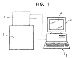
- FIG. 1 is a schematic front view showing an image producing apparatus which is an embodiment of the present invention.
- the image producing apparatus according to this embodiment is adapted to detect chemiluminescence emission generated by contacting a chemiluminescent substance with a labeling substance and a fluorescent light emitted from an image carrier carrying an image of a fluorescent substance and produce a visual image.
- the image producing apparatus includes an imaging device 1, a dark box 2 and a personal computer 3.
- the personal computer 3 is equipped with a CRT 4 and a keyboard 5.
- Figure 2 is a schematic longitudinal cross sectional view showing the imaging device 1.
- the imaging device 1 includes a CCD (charge coupled device) 10, a heat transfer plate 11 made of metal such as aluminum, a Peltier element 12, a shutter 13 positioned in front of the CCD 10, an A/D converter 14 for converting analog image data produced by the CCD 10 to digital image data, an image data buffer 15 for temporarily storing image data digitized by the A/D converter 14 and a camera control circuit 16 for controlling the operation of the imaging device 1.
- An opening portion formed between the imaging device and the dark box 2 is closed by a glass plate 17 and the periphery of the imaging device 1 is formed with heat dispersion fins 18 over substantially half its length for dispersing heat released from the Peltier element 11.
- An image intensifier 19 disposed in the dark box 2 is provided in front of the glass plate 17 and a camera lens 20 is mounted on the front surface of the image intensifier 19.
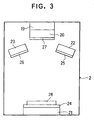
- Figure 3 is a schematic longitudinal cross sectional view of the dark box 2.
- the dark box 2 is equipped with a first blue light emitting diode stimulating ray source 21 for emitting a stimulating ray whose center wavelength is 450 nm and a second blue light emitting diode stimulating ray source 22 and a third blue light emitting diode stimulating ray source 23 are provided obliquely above the first blue light emitting diode stimulating ray source 21, each being adapted for emitting a stimulating ray whose center wavelength is 450 nm.
- a filter 24 is adhered to the upper surface of the first blue light emitting diode stimulating ray source 21 and filters 25, 26 are respectively adhered to the front surfaces of the second blue light emitting diode stimulating ray source 22 and the third blue light emitting diode stimulating ray source 23.
- the filters 24, 25, 26 cut light of wavelengths other than one in the vicinity of 450 nm and harmful to the stimulation of a fluorescent substance and transmit light having a wavelength in the vicinity of 450 nm.
- a filter 27 for cutting the stimulating ray having a wavelength in the vicinity of 450 nm is detachably provided on the front surface of the camera lens 20.
- the reference numeral 28 designates an image carrier carrying an image of fluorescent substance.
- Figure 4 is a block diagram of the personal computer 3 and the peripheral devices thereof.
- the personal computer 3 includes a CPU 30 for controlling the exposure of the CCD 10, a timer means 31 for storing an exposure time input by a user, an image data storing means 32 for storing image data produced by the imaging device 1, an image data transferring means 33 for transferring the image data produced by the imaging device 1 to the image data storing means 32, an image processing means 34 for effecting image processing on the image data stored in the image data storing means 32 and an image producing means 35 for producing a visual image on the screen of the CRT 4 based on the image data stored in the image data storing means 32.
- a CPU 30 for controlling the exposure of the CCD 10
- a timer means 31 for storing an exposure time input by a user
- an image data storing means 32 for storing image data produced by the imaging device 1
- an image data transferring means 33 for transferring the image data produced by the imaging device 1 to the image data storing means 32
- an image processing means 34 for effecting image processing on the image data stored in the image data storing means 32
- the first blue light emitting diode stimulating ray source 21, the second blue light emitting diode stimulating ray source 22 and the third blue light emitting diode stimulating ray source 23 are controlled by a light source control means 36 and an instruction signal can be input via the CPU 30 to the light source control means 36 through the keyboard 5.
- the thus constituted image producing apparatus detects fluorescent light from the image carrier 28 carrying an image of a fluorescent substance and produces a visual image in the following manner.
- the exposure time T is stored in the timer means 31.
- the image carrier 28, which is a specimen, is then placed on the filter 24 and lens focus is adjusted by the user.
- the user inputs an exposure start signal through the keyboard 5.
- the first blue light emitting diode stimulating ray source 21 alone or the second blue light emitting diode stimulating ray source 22 and the third blue light emitting diode stimulating ray source 23 are turned on by the light source control means 36, thereby emitting a stimulating ray toward the image carrier 28.
- Light components of wavelengths not in the vicinity of 450 nm are cut by the filters 24, 25, 26 from the stimulating rays emitted from the first blue light emitting diode stimulating ray source 21 alone or the second blue light emitting diode stimulating ray source 22 and the third blue light emitting diode stimulating ray source 23.
- the fluorescent substance contained in the image carrier 28 is stimulated by light having a wavelength in the vicinity of 450 nm, thereby emitting fluorescent light.
- the fluorescent light emitted from the fluorescent substance contained in the image carrier 28 enters the photoelectrical surface of the image intensifier 19 via the filter 27 and the camera lens 20 and amplified so that an image is formed on the fluorescent surface of the image intensifier 19.
- the CCD 10 of the imaging device 1 receives light from the image formed on the fluorescent surface of the image intensifier 19 to convert electric charges and accumulates them. Since light components having wavelengths in the vicinity of 450 nm are cut by the filter 27, only fluorescent light emitted from the fluorescent substance contained in the image carrier 28 is received by the CCD 10 of the imaging device 1.
- the CPU 30 When the exposure time has passed, the CPU 30 outputs an exposure completion signal to the imaging device 1 and causes the CCD 10 to transfer electric charges accumulated therein to the A/D converter 14 and the A/D converter 14 to produce digital image data. At the same time, the CPU 30 outputs a data transfer signal to the image data transferring means 33 to store the digital image data produced by the imaging device 1 in the image data storing means 32.
- the image processing means 34 effects image processing on the read out digital image data and a visual image is produced on the screen of the CRT 4 based on the image-processed digital image data from the image producing means 35.
- a chemiluminescent image is produced in the same manner as a fluorescent image except that the filter 27 is removed and the first blue light emitting diode stimulating ray source 21, the second blue light emitting diode stimulating ray source 22 and the third blue light emitting diode stimulating ray source 23 are kept to be off, chemiluminescent emission emitted from the image carrier 28 is photoelectrically detected by the CCD 10 via the camera lens 20 and the image intensifier 19 to produce image data and a chemiluminescent image is produced on the screen of the CRT 4.
- the CPU 30 is constituted so as not to output an operation signal to the light source control means 36 when an instruction signal requesting the production of a chemiluminescent image is input together with an exposure start signal through the keyboard 5.
- the first blue light emitting diode stimulating ray source 21, the second blue light emitting diode stimulating ray source 22 and the third blue light emitting diode stimulating ray source 23 are used as a stimulating source for stimulating a fluorescent substance contained in the image carrier 28, it is unnecessary to take measures to prevent the user from being exposed to ultraviolet rays and, therefore, it is possible to safely produce a fluorescent image at low cost.
- the light emitting diode stimulating ray sources 21, 22, 23 used generate less heat than an ultraviolet ray source, it is unnecessary to take measures for heat dispersion. Therefore, since the dark box 2 can be completely shielded from light and extremely weak chemiluminescent emission can be detected, it is possible to produce a fluorescent image by the fluorescence detecting system and a chemiluminescent image by the chemiluminescent detecting system using a single image producing apparatus.
- Figure 5 is a schematic exploded view showing a fluorescent image visualizing device which is another embodiment of the present invention and Figure 6 is a schematic perspective view thereof.
- the fluorescent image visualizing device 40 includes a blue light emitting diode array base plate 42 provided with a plurality of blue light emitting diodes 41 for emitting a stimulating ray whose center wavelength is 450 nm, a bandpass filter 43 placed on the blue light emitting diode array base plate 42, a diffusion plate 44 made of opal glass, slightly opaque acrylic resin or the like, and a transparent cover glass 45 placed on the diffusion plate 44.
- a gel containing specimen labeled with a fluorescent substance and electrophoresed is placed on the transparent cover glass 45.
- the bandpass filter 43 is provided for improving the contrast of a fluorescent image and the transparent cover glass 45 is provided for preventing the diffusion plate 44 from being damaged when a band portion of a target substance is cut out with a knife.
- the thus constituted fluorescent image visualizing device 40 When the thus constituted fluorescent image visualizing device 40 is located in a slightly dark ambience and the plurality of blue light emitting diodes 41 of the blue light emitting diode array base plate 42 are turned on, blue light is emitted from the plurality of blue light emitting diodes 41.
- the blue light passing through the bandpass filter 43 is converted to non-directional light by passing through the diffusion plate 44 and impinges on the gel 46 via the transparent cover glass 45.
- the gel 46 is formed with bands 47 of the specimen labeled with a fluorescent substance and electrophoresed and the fluorescent substance is stimulated by light impinging on the gel and having a wavelength in the vicinity of 450 nm, thereby emitting fluorescent light from the bands 47.
- the thus emitted fluorescent light can be viewed with the eyes and, therefore, an electrophoresis image of the specimen can be visualized in this manner.
- the bands can be viewed with the eyes, even if the amount of light emitted from the fluorescent substance is small.
- the bands 47 of the specimen labeled with a fluorescent substance and electrophoresed on the gel 46 it is possible to safely view the bands 47 of the specimen labeled with a fluorescent substance and electrophoresed on the gel 46 and analyze a target substance by finding a band portion where the target substance is distributed, picking out it by means of cutting it out with a knife, sucking it out or the like and further processing it.
- Figure 7 is a schematic perspective view showing a fluorescent image visualizing device which is a further embodiment of the present invention.
- the fluorescent image visualizing device 40 includes a blue light emitting diode array base plate 42 provided with a plurality of blue light emitting diodes (not shown) for emitting a stimulating ray whose center wavelength is 450 nm, a bandpass filter 43 placed on the blue light emitting diode array base plate 42, a diffusion plate 44 and a transparent cover glass 45 placed on the diffusion plate 44.
- an electrophoresis tank 52 provided with electrodes 50, 51 is placed on the transparent cover glass 45 and a gel 46 is set in the electrophoresis tank 52 so that a specimen labeled with a fluorescent substance can be electrophoresed therein.
- the fluorescent image visualizing device 40 is located in a slightly dark ambience and voltage is applied to the gel 46 via the electrodes 50, 51, thereby electrophoresing a specimen in the electrophoresis tank 52.
- the plurality of blue light emitting diodes of the blue light emitting diode array base plate 42 are then turned on and, similarly to in the previous embodiment, the electrophoresis image is visualized.
- the band portion where the target substance is distributed can be found and the target substance can be analyzed by picking it out by cutting with a knife, sucking or the like, and further processing it.
- the specimen can be electrophoresed and an electrophoresis image can be safely visualized in situ.
- Figure 8 is a schematic vertical cross sectional view showing a dark box of an image producing apparatus which is a further embodiment of the present invention.
- the dark box 2 of the image producing apparatus is equipped with a fluorescent image visualizing device 40 shown in Figures 5 and 6 instead of the first blue light emitting diode stimulating ray source 21 and the filter 24 and the second blue light emitting diode stimulating ray source 22 and the third blue light emitting diode stimulating ray source 23 are not provided.
- the image producing apparatus includes a blue light emitting diode array base plate 42 provided with a plurality of blue light emitting diodes 41 for emitting a stimulating ray whose center wavelength is 450 nm, a bandpass filter 43 placed on the blue light emitting diode array base plate 42, a diffusion plate 44 made of opal glass, slightly opaque acrylic resin or the like, and a transparent cover glass 45 placed on the diffusion plate 44.
- a gel containing a specimen labeled with a fluorescent substance and electrophoresed is placed on the transparent cover glass 45.
- the filter 27 is secured to the front surface of the camera lens 20 for cutting light of a wavelength equal to that of the stimulating ray emitted from the plurality of blue light emitting diodes 41.
- Figure 9 is a block diagram of a personal computer and the peripheral devices thereof.
- the personal computer 3 includes a CPU 30 for controlling the exposure of the CCD 10, a timer means 31 for storing an exposure time input by a user, an image data transferring means 33 for reading out image data produced by the imaging device from the image data buffer 15, an image processing means 34 for effecting image processing on the image data read out by the image data transferring means 33 and storing them in an image data storing means 32, and an image producing means 35 for displaying a visual image on the screen of the CRT 4 based on the image data stored in the image data storing means 32.
- the plurality of blue light emitting diodes 41 are controlled by the light source control means 36 and an instruction signal can be input via the CPU 30 to the light source control means 36 through the keyboard 5.
- the CPU 30 is adapted to output various signals to the camera control circuit 16 of the imaging device 1.
- the CPU 30 when a user inputs a lens focus adjusting signal through the keyboard 5, the CPU 30 outputs a lens focus adjusting mode signal to the camera control circuit 16.
- the camera control circuit 16 receives the lens focus adjusting mode signal, it controls a reading operation control circuit (not shown) to cause it to transfer image data stored in the CCD 10 in the form of electric charges every predetermined time period.
- the gel 46 containing a specimen labeled with a fluorescent substance and electrophoresed is placed on the transparent cover glass 45 by the user and the camera lens 20 is operated to adjust the lens focus.
- the dark box 2 is closed.
- the plurality of blue light emitting diodes 41 are turned on by the light source control means 36 and a stimulating ray is emitted toward the gel 46.
- the exposure start signal is input to the camera control circuit 16 and the shutter 13 is opened to start the exposure of the CCD 10.
- Bands of the specimen labeled by fluorescent substance and electrophoresed are formed on the gel 46 and when they are irradiated with the stimulating ray emitted from the plurality of blue light emitting diodes 41, the fluorescent substance is stimulated to emit fluorescent light.
- the fluorescent light emitted from the fluorescent substance impinges on the fluorescent surface of the image intensifier 19 via the filter 27 and the camera lens 20 to form an image.
- the CCD 10 receives light from the image formed on the fluorescent surface of the image intensifier 19, converts it to electric charges and accumulates the charges. Since light having a wavelength equal to that of the stimulating ray is cut by the filter 27, only fluorescent light emitted from the fluorescent substance in the specimen contained in the gel 46 is received by the CCD 10 of the imaging device 1.
- the CPU 30 When a predetermined exposure time has passed, the CPU 30 outputs an exposure completion signal to the camera control circuit 16 of the imaging device 1.
- the camera control circuit 16 receives the exposure completion signal from the CPU 30, it causes the CCD 10 to transfer analog image data accumulated therein in the form of electric charges to the A/D converter 14 and causes the A/D converter 14 to digitize them.
- the digital image data are temporarily stored in the image data buffer 15.
- the CPU 30 outputs a data transferring signal to the image transferring means 33 and causes it to read out the digital image data temporarily stored in the image data buffer 15 of the imaging device and to input them to the image processing means 34.
- the image processing means 34 effects image processing on the image data input from the image data transferring means 33 and stores them in the image data storing means 32.
- the digital image data stored in the image data storing means 32 are read out by the image producing means 35 and, based on the read out image data, a fluorescent image containing bands of the specimen is displayed on the screen on the CRT 4.
- the imaging device 1 including the CCD 10 it is possible to visualize an electrophoresis image of the specimen on the screen of the CRT 4 by the imaging device 1 including the CCD 10, find a band portion where the target substance is distributed, pick out the portion by cutting it out with a knife, sucking it out or the like, further process it and analyze the target substance.
- CCD 10 Charge Injection Device
- PDA Photo-Diode Array
- MOS MOS type imaging element
- the imaging device 1 includes the Peltier element 12 for cooling the CCD 10 and the heat dispersion fins 18 on the periphery of the imaging device 1 for dispersing heat emitted from the Peltier element 12, it is not absolutely necessary to provide the Peltier element 12 and the heat dispersion fins 18 and they may be omitted depending on the intensity of fluorescent light emitted from fluorescent substance.
- the first blue light emitting diode stimulating ray source 21, the second blue light emitting diode stimulating ray source 22 and the third blue light emitting diode stimulating ray source 23 are provided in the dark box 2, only the first blue light emitting diode stimulating ray source 21, or only the second blue light emitting diode stimulating ray source 22 and the third blue light emitting diode stimulating ray source 23 may be provided.
- the first blue light emitting diode stimulating ray source 21, the second blue light emitting diode stimulating ray source 22, the third blue light emitting diode stimulating ray source 23 and the blue light emitting diodes 41 employed in the above described embodiments are each adapted to emit stimulating rays whose center wavelength is 450 nm, because many kinds of fluorescent substances used in fluorescent detection systems are designed to be effectively stimulated by an argon laser source for emitting a laser beam having a wavelength of 480 nm.
- a light emitting diode stimulating ray source for emitting light whose center wavelength is in the range between 400 and 700 nm may be employed depending on the kind of fluorescent substance.
- an exposure time T may be automatically determined by determining exposure times T in accordance with the kinds of image carrier 28 and the kinds of fluorescent substance in advance, storing them in the personal computer 3 and inputting the kind of image carrier 28 or the kind of fluorescent substance through the keyboard 5.
- the first blue light emitting diode stimulating ray source 21 alone or the second blue light emitting diode stimulating ray source 22 and the third blue light emitting diode stimulating ray source 23 are turned on by the light source control means 36.
- the light source control means 36 it is not absolutely necessary to constitute the light source control means 36 so as to be controlled by the personal computer 3 and the light source control means 36 may be manually operated.
- the filter 27 for cutting light having a wavelength in the vicinity of 450 nm is detachably mounted on the front surface of the camera lens 20 and the image producing apparatus is constituted so as to be able to detect extremely weak chemiluminescent emission and produce a chemiluminescent image when the filter 27 is removed.
- the image producing apparatus may be constituted so as to produce only a fluorescent image by the fluorescent detection system, in which case the filter 27 can be fixed to the front surface of the camera lens 20.
- the transparent cover glass 45 is provided on the diffusion plate 44, if the diffusion plate 44 is made of material resistant to damage, it is unnecessary to provide the transparent cover glass 45.
- the electrophoresis image of the specimen is visualized, a portion where a target substance is distributed is found, picked out by cutting it out or sucking it out and further processed and the target substance is analyzed.
- an image producing apparatus which uses a solid state image sensor and can safely produce a fluorescent image at low cost.
Claims (8)
- Bilderzeugungsvorrichtung, umfassend mindestens eine Leuchtdioden-Anregungsstrahlenquelle (21-23; 41, 42), eine Filtereinrichtung (27, 43) zum Sperren eines von der mindestens einen Leuchtdioden-Anregungsstrahlenquelle (21-23; 41, 42) emittierten Anregungsstrahls und zum Ermöglichen, daß nur durch die Anregung einer fluoreszierenden Substanz durch den Anregungsstrahl erzeugtes Fluoreszenzlicht hindurchgelangt, und einen Festkörperbildsensor (10) zum Detektieren das durch die Filtereinrichtung (27, 43) transmittierten Fluoreszenzlichts, dadurch gekennzeichnet, daß die Anregungssstrahlenquelle eine Leuchtdiodenbasisplatte (42) mit mehreren Leuchtdioden-Anregungsstrahlenquellen (41) und eine an der Leuchtdiodenbasisplatte (42) angeordnete Diffusionsplatte (44) enthält, auf der ein Gel (46), welches eine Elektrophoreseprobe enthält, plaziert ist.
- Bilderzeugungsvorrichtung, umfassend mindestens eine Leuchtdioden-Anregungsstrahlenquelle (21-23; 41, 42), eine Filtereinrichtung (27, 43) zum Sperren eines von der mindestens einen Leuchtdioden-Anregungsstrahlenquelle (21-23; 41, 42) emittierten Anregungsstrahls und zum Ermöglichen, daß nur durch die Anregung einer fluoreszierenden Substanz durch den Anregungsstrahl erzeugtes Fluoreszenzlicht hindurchgelangt, und einen Festkörperbildsensor (10) zum Detektieren das durch die Filtereinrichtung (27, 43) transmittierten Fluoreszenzlichts, dadurch gekennzeichnet, daß die Anregungsstrahlenquelle eine Leuchtdiodenbasisplatte (42) mit mehreren Leuchtdioden-Anregungsstrahlenquellen (41) und eine an der Leuchtdiodenbasisplatte (42) angeordnete Diffusionsplatte (44) enthält, an der ein Elektrophoresetank (52) angeordnet ist, der ein Gel enthält, welches eine Elektrophoreseprobe enthält.
- Vorrichtung nach Anspruch 1 oder 2, bei der die Anregungsstrahlenquelle (21-23; 41, 42) derart ausgebildet ist, daß sie einen Anregungsstrahl emittiert, dessen Mittenwellenlänge zwischen 400 nm und 700 nm liegt.
- Vorrichtung nach Anspruch 3, bei der die Anregungsstrahlenquelle (21-23; 41, 42) derart ausgebildet ist, daß sie einen Anregungsstrahl emittiert, dessen Mittenwellenlänge zwischen 400 nm und 550 nm liegt.
- Vorrichtung nach Anspruch 4, bei der die Anregungsstrahlenquelle (21-23; 41, 42) als blaues Licht emittierende Leuchtdiode zum Emittieren eines Anregungsstrahls ausgebildet ist, dessen Mittenwellenlänge zwischen 400 nm und 500 nm liegt.
- Vorrichtung nach einem der Ansprüche 1 bis 5, bei der die Filtereinrichtung (27, 43) lösbar ist.
- Vorrichtung nach einem der Ansprüche 1 bis 6, bei der der Festkörperbildsensor (10) durch eine gekühlte CCD gebildet ist.
- Vorrichtung nach einem der Ansprüche 1 bis 7, bei der ein Bildverstärker (19) vor dem Festkörperbildsensor (10) angeordnet ist.
Applications Claiming Priority (6)
| Application Number | Priority Date | Filing Date | Title |
|---|---|---|---|
| JP8289747A JPH10132744A (ja) | 1996-10-31 | 1996-10-31 | 画像生成装置 |
| JP28974796 | 1996-10-31 | ||
| JP289747/96 | 1996-10-31 | ||
| JP9079441A JPH10274637A (ja) | 1997-03-31 | 1997-03-31 | 蛍光画像可視化装置 |
| JP7944197 | 1997-03-31 | ||
| JP79441/97 | 1997-03-31 |
Publications (3)
| Publication Number | Publication Date |
|---|---|
| EP0840114A2 EP0840114A2 (de) | 1998-05-06 |
| EP0840114A3 EP0840114A3 (de) | 2000-01-19 |
| EP0840114B1 true EP0840114B1 (de) | 2005-02-16 |
Family
ID=26420468
Family Applications (1)
| Application Number | Title | Priority Date | Filing Date |
|---|---|---|---|
| EP97118850A Expired - Lifetime EP0840114B1 (de) | 1996-10-31 | 1997-10-29 | Bilderzeugende Vorrichtung |
Country Status (3)
| Country | Link |
|---|---|
| US (1) | US5856866A (de) |
| EP (1) | EP0840114B1 (de) |
| DE (1) | DE69732510T2 (de) |
Families Citing this family (8)
| Publication number | Priority date | Publication date | Assignee | Title |
|---|---|---|---|---|
| DE69837839T2 (de) | 1997-03-07 | 2007-12-13 | Clare Chemical Research LLC, Denver | Fluorometrischer Nachweis mit sichtbarem Light |
| US6914250B2 (en) * | 1997-03-07 | 2005-07-05 | Clare Chemical Research, Inc. | Fluorometric detection using visible light |
| JP3723145B2 (ja) * | 2002-03-28 | 2005-12-07 | 富士写真フイルム株式会社 | 撮像装置、画像処理装置ならびに撮像システム |
| US6878949B2 (en) | 2002-08-22 | 2005-04-12 | Genextix Limited | Gel imaging and excision |
| JP4343801B2 (ja) * | 2004-09-03 | 2009-10-14 | オリンパス株式会社 | 蛍光観察用暗箱装置、蛍光観察システムおよび蛍光観察方法 |
| US20100295939A1 (en) * | 2008-01-28 | 2010-11-25 | Innovative Imaging, Inc | Table gauge |
| CN101949886A (zh) * | 2010-08-27 | 2011-01-19 | 亚亚科技股份有限公司 | 实时荧光电泳装置 |
| US10186539B2 (en) | 2014-10-13 | 2019-01-22 | Bio-Rad Laboratories, Inc. | Heated image sensor window |
Family Cites Families (11)
| Publication number | Priority date | Publication date | Assignee | Title |
|---|---|---|---|---|
| US4184196A (en) * | 1975-11-28 | 1980-01-15 | Moret Michel A | Diagnostic lamp, particularly for checking teeth |
| DE3037983C2 (de) * | 1980-10-08 | 1983-03-31 | Fa. Carl Zeiss, 7920 Heidenheim | Verfahren und Vorrichtung zur lichtinduzierten rastermikroskopischen Darstellung von Probenparametern in ihrer räumlichen Verteilung |
| US4942303A (en) * | 1989-01-31 | 1990-07-17 | Associated Universities, Inc. | Computer controlled fluorometer device and method of operating same |
| GB2231958A (en) * | 1989-04-07 | 1990-11-28 | Hamamatsu Photonics Kk | Measuring fluorescence characteristics |
| ATE266195T1 (de) * | 1992-09-14 | 2004-05-15 | Stanford Res Inst Int | Up-converting reporter molekül für biologische und andere testverfahren unter verwendung von laseranregungstechniken |
| US5304809A (en) * | 1992-09-15 | 1994-04-19 | Luxtron Corporation | Luminescent decay time measurements by use of a CCD camera |
| JP3563140B2 (ja) * | 1995-01-19 | 2004-09-08 | 株式会社日立製作所 | キャピラリーアレイ電気泳動装置 |
| US5578832A (en) * | 1994-09-02 | 1996-11-26 | Affymetrix, Inc. | Method and apparatus for imaging a sample on a device |
| US5653539A (en) * | 1994-05-02 | 1997-08-05 | Rosengaus; Eliezer | Method and apparatus for remotely measuring the temperature of a surface |
| US5459325A (en) * | 1994-07-19 | 1995-10-17 | Molecular Dynamics, Inc. | High-speed fluorescence scanner |
| US6074870A (en) * | 1994-08-15 | 2000-06-13 | Becton, Dickinson And Company | Optical blood culture sensor |
-
1997
- 1997-10-29 DE DE69732510T patent/DE69732510T2/de not_active Expired - Lifetime
- 1997-10-29 EP EP97118850A patent/EP0840114B1/de not_active Expired - Lifetime
- 1997-10-30 US US08/960,598 patent/US5856866A/en not_active Expired - Lifetime
Also Published As
| Publication number | Publication date |
|---|---|
| EP0840114A3 (de) | 2000-01-19 |
| DE69732510D1 (de) | 2005-03-24 |
| EP0840114A2 (de) | 1998-05-06 |
| DE69732510T2 (de) | 2005-08-25 |
| US5856866A (en) | 1999-01-05 |
Similar Documents
| Publication | Publication Date | Title |
|---|---|---|
| EP0713086B1 (de) | Vorrichtung und Verfahren zum Erkennen und Zählen von selten vorkommenden Säugerzellen | |
| US5672881A (en) | Charge-coupled device imaging apparatus | |
| EP0488422B1 (de) | Vorrichtung zur Auswertung fluoreszenzmarkierter Gelelektrophoresemuster | |
| US5556529A (en) | DNA base sequencer | |
| US5552322A (en) | DNA base sequencer | |
| US6791618B1 (en) | Photographing system with improved time setting | |
| US20030020022A1 (en) | Fluorescence reading apparatus | |
| EP0626578B1 (de) | Gelelektrophoresegerät | |
| US6195469B1 (en) | Image processing apparatus for shading correction | |
| EP0459278B1 (de) | Gerät zum Lesen eines Fluorenszenzmusters | |
| JPH09281078A (ja) | Dna塩基配列決定装置 | |
| EP0840114B1 (de) | Bilderzeugende Vorrichtung | |
| US6567125B1 (en) | Imaging apparatus with power reduction and correcting devices | |
| US6351286B1 (en) | Image producing apparatus enabling a user to evaluate an intermediate image | |
| US7053397B1 (en) | Fluorescent image reading apparatus | |
| JP2000292353A (ja) | 蛍光画像生成装置 | |
| US6996289B1 (en) | Image processing apparatus and method which defines abnormal pixels by reading density signal levels | |
| JPH10132744A (ja) | 画像生成装置 | |
| US20050219368A1 (en) | Photography system | |
| JPH10274637A (ja) | 蛍光画像可視化装置 | |
| EP2988490B1 (de) | Fotografievorrichtung und -verfahren | |
| JPH10215395A (ja) | 画像生成装置 | |
| US6493459B2 (en) | Image reading apparatus | |
| JPH10210408A (ja) | 画像生成装置 | |
| JP2001083091A (ja) | 画像読み取り装置 |
Legal Events
| Date | Code | Title | Description |
|---|---|---|---|
| PUAI | Public reference made under article 153(3) epc to a published international application that has entered the european phase |
Free format text: ORIGINAL CODE: 0009012 |
|
| AK | Designated contracting states |
Kind code of ref document: A2 Designated state(s): DE FR SE |
|
| AX | Request for extension of the european patent |
Free format text: AL;LT;LV;RO;SI |
|
| PUAL | Search report despatched |
Free format text: ORIGINAL CODE: 0009013 |
|
| AK | Designated contracting states |
Kind code of ref document: A3 Designated state(s): AT BE CH DE DK ES FI FR GB GR IE IT LI LU MC NL PT SE |
|
| AX | Request for extension of the european patent |
Free format text: AL;LT;LV;RO;SI |
|
| 17P | Request for examination filed |
Effective date: 20000504 |
|
| AKX | Designation fees paid |
Free format text: DE FR SE |
|
| 17Q | First examination report despatched |
Effective date: 20021217 |
|
| GRAP | Despatch of communication of intention to grant a patent |
Free format text: ORIGINAL CODE: EPIDOSNIGR1 |
|
| GRAS | Grant fee paid |
Free format text: ORIGINAL CODE: EPIDOSNIGR3 |
|
| GRAA | (expected) grant |
Free format text: ORIGINAL CODE: 0009210 |
|
| AK | Designated contracting states |
Kind code of ref document: B1 Designated state(s): DE FR SE |
|
| REF | Corresponds to: |
Ref document number: 69732510 Country of ref document: DE Date of ref document: 20050324 Kind code of ref document: P |
|
| REG | Reference to a national code |
Ref country code: SE Ref legal event code: TRGR |
|
| PLBE | No opposition filed within time limit |
Free format text: ORIGINAL CODE: 0009261 |
|
| STAA | Information on the status of an ep patent application or granted ep patent |
Free format text: STATUS: NO OPPOSITION FILED WITHIN TIME LIMIT |
|
| ET | Fr: translation filed | ||
| 26N | No opposition filed |
Effective date: 20051117 |
|
| REG | Reference to a national code |
Ref country code: FR Ref legal event code: TP Ref country code: FR Ref legal event code: CD |
|
| PGFP | Annual fee paid to national office [announced via postgrant information from national office to epo] |
Ref country code: FR Payment date: 20131009 Year of fee payment: 17 Ref country code: DE Payment date: 20131023 Year of fee payment: 17 Ref country code: SE Payment date: 20131011 Year of fee payment: 17 |
|
| REG | Reference to a national code |
Ref country code: DE Ref legal event code: R119 Ref document number: 69732510 Country of ref document: DE |
|
| REG | Reference to a national code |
Ref country code: SE Ref legal event code: EUG |
|
| PG25 | Lapsed in a contracting state [announced via postgrant information from national office to epo] |
Ref country code: SE Free format text: LAPSE BECAUSE OF NON-PAYMENT OF DUE FEES Effective date: 20141030 Ref country code: DE Free format text: LAPSE BECAUSE OF NON-PAYMENT OF DUE FEES Effective date: 20150501 |
|
| REG | Reference to a national code |
Ref country code: FR Ref legal event code: ST Effective date: 20150630 |
|
| PG25 | Lapsed in a contracting state [announced via postgrant information from national office to epo] |
Ref country code: FR Free format text: LAPSE BECAUSE OF NON-PAYMENT OF DUE FEES Effective date: 20141031 |