EP0840083A2 - Zwischenwand für Wärmetauscher - Google Patents
Zwischenwand für Wärmetauscher Download PDFInfo
- Publication number
- EP0840083A2 EP0840083A2 EP97307762A EP97307762A EP0840083A2 EP 0840083 A2 EP0840083 A2 EP 0840083A2 EP 97307762 A EP97307762 A EP 97307762A EP 97307762 A EP97307762 A EP 97307762A EP 0840083 A2 EP0840083 A2 EP 0840083A2
- Authority
- EP
- European Patent Office
- Prior art keywords
- manifold
- slit
- tube
- brazing material
- applying
- Prior art date
- Legal status (The legal status is an assumption and is not a legal conclusion. Google has not performed a legal analysis and makes no representation as to the accuracy of the status listed.)
- Withdrawn
Links
- 238000000034 method Methods 0.000 claims abstract description 26
- 238000005219 brazing Methods 0.000 claims description 16
- 239000000463 material Substances 0.000 claims description 16
- 239000003795 chemical substances by application Substances 0.000 claims description 2
- 238000004320 controlled atmosphere Methods 0.000 claims description 2
- 239000007767 bonding agent Substances 0.000 abstract 1
- 239000012530 fluid Substances 0.000 description 33
- 230000008569 process Effects 0.000 description 4
- 238000002788 crimping Methods 0.000 description 2
- 238000004519 manufacturing process Methods 0.000 description 2
- 229910000838 Al alloy Inorganic materials 0.000 description 1
- 238000004378 air conditioning Methods 0.000 description 1
- XAGFODPZIPBFFR-UHFFFAOYSA-N aluminium Chemical compound [Al] XAGFODPZIPBFFR-UHFFFAOYSA-N 0.000 description 1
- 229910052782 aluminium Inorganic materials 0.000 description 1
- 239000004411 aluminium Substances 0.000 description 1
- 238000001816 cooling Methods 0.000 description 1
- 230000007812 deficiency Effects 0.000 description 1
- 238000005238 degreasing Methods 0.000 description 1
- 230000004907 flux Effects 0.000 description 1
- 238000010438 heat treatment Methods 0.000 description 1
- 238000005304 joining Methods 0.000 description 1
- 230000013011 mating Effects 0.000 description 1
- 238000010297 mechanical methods and process Methods 0.000 description 1
- 230000005226 mechanical processes and functions Effects 0.000 description 1
- 238000012986 modification Methods 0.000 description 1
- 230000004048 modification Effects 0.000 description 1
- 230000037361 pathway Effects 0.000 description 1
- 238000004064 recycling Methods 0.000 description 1
- 229910000679 solder Inorganic materials 0.000 description 1
- 238000003466 welding Methods 0.000 description 1
Images


Classifications
-
- F—MECHANICAL ENGINEERING; LIGHTING; HEATING; WEAPONS; BLASTING
- F28—HEAT EXCHANGE IN GENERAL
- F28D—HEAT-EXCHANGE APPARATUS, NOT PROVIDED FOR IN ANOTHER SUBCLASS, IN WHICH THE HEAT-EXCHANGE MEDIA DO NOT COME INTO DIRECT CONTACT
- F28D1/00—Heat-exchange apparatus having stationary conduit assemblies for one heat-exchange medium only, the media being in contact with different sides of the conduit wall, in which the other heat-exchange medium is a large body of fluid, e.g. domestic or motor car radiators
- F28D1/02—Heat-exchange apparatus having stationary conduit assemblies for one heat-exchange medium only, the media being in contact with different sides of the conduit wall, in which the other heat-exchange medium is a large body of fluid, e.g. domestic or motor car radiators with heat-exchange conduits immersed in the body of fluid
- F28D1/04—Heat-exchange apparatus having stationary conduit assemblies for one heat-exchange medium only, the media being in contact with different sides of the conduit wall, in which the other heat-exchange medium is a large body of fluid, e.g. domestic or motor car radiators with heat-exchange conduits immersed in the body of fluid with tubular conduits
- F28D1/047—Heat-exchange apparatus having stationary conduit assemblies for one heat-exchange medium only, the media being in contact with different sides of the conduit wall, in which the other heat-exchange medium is a large body of fluid, e.g. domestic or motor car radiators with heat-exchange conduits immersed in the body of fluid with tubular conduits the conduits being bent, e.g. in a serpentine or zig-zag
- F28D1/0475—Heat-exchange apparatus having stationary conduit assemblies for one heat-exchange medium only, the media being in contact with different sides of the conduit wall, in which the other heat-exchange medium is a large body of fluid, e.g. domestic or motor car radiators with heat-exchange conduits immersed in the body of fluid with tubular conduits the conduits being bent, e.g. in a serpentine or zig-zag the conduits having a single U-bend
-
- F—MECHANICAL ENGINEERING; LIGHTING; HEATING; WEAPONS; BLASTING
- F28—HEAT EXCHANGE IN GENERAL
- F28F—DETAILS OF HEAT-EXCHANGE AND HEAT-TRANSFER APPARATUS, OF GENERAL APPLICATION
- F28F9/00—Casings; Header boxes; Auxiliary supports for elements; Auxiliary members within casings
- F28F9/02—Header boxes; End plates
- F28F9/0202—Header boxes having their inner space divided by partitions
- F28F9/0204—Header boxes having their inner space divided by partitions for elongated header box, e.g. with transversal and longitudinal partitions
- F28F9/0214—Header boxes having their inner space divided by partitions for elongated header box, e.g. with transversal and longitudinal partitions having only longitudinal partitions
Definitions
- the present invention relates generally to heat exchangers used in automotive air conditioning systems, such as condensers, evaporators and oil coolers. More particularly, the present invention relates to a method for forming an internal, integral baffle in a heat exchanger.
- Fin and tube type heat exchangers are commonly used in vehicle, industrial and residential environments for heating and cooling purposes.
- these heat exchangers utilise a plurality of tubes through which the fluid to be heated or cooled passes.
- the number of tubes utilised depends on the thermal capacity requirements of the fin and tube heat exchanger.
- manifolds are used having a series of openings corresponding to and mating with the ends of the tubes.
- the manifolds have an inlet port and an outlet port which circulate the fluid through the heat exchanger and then returns the fluid to a remote location for subsequent recycling.
- the heat exchanger fluid makes multiple passes through the heat exchanger to increase its efficiency. These multiple passes are accomplished by obstructing the fluid flow at key locations and forcing the fluid across the heat exchanger.
- the obstructions are baffles placed within the manifold.
- Several methods are known for placing baffles within a manifold. In one method, a circular disk of material is place within a predefined aperture in the manifold and welded there. In another method, such as disclosed in U.S. Patent No. 5,090,477 a baffle is mechanically formed by crimping the manifold so that one portion of the manifold wall contacts an opposite portion of the manifold wall.
- the ⁇ 477 patent teaches that because of the plastic deformation of the manifold wall, a leak tight seal is formed and brazing is not required further secure the baffle within the manifold. However, if the manifold is used on a heat exchanger requiring extremely high internal pressures, the baffle may leak. Therefore it would be advantageous to provide a manifold with an internally formed baffle that can withstand high pressures.
- the present invention overcomes the difficulties and deficiencies associated with prior art devices by providing a method of forming internal, integral baffles at baffle locations in a heat exchange manifold, comprising the steps of permanently collapsing the manifold at the baffle locations such that the manifold wall top and the manifold wall bottom form a generally U-shaped depression in the manifold and forming a slit in the U-shaped depression.
- the method further includes the steps of applying a brazing material to the manifold, causing the brazing material to flow through the slit and between the manifold wall top and manifold wall bottom and processing the manifold at predetermined conditions to secure the manifold wall top and bottom together.
- the method provides the advantages of a stronger bond strength at the baffle, thus increasing the burst strength of the manifold.
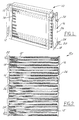
- Figures 1 and 2 show two different types of tube and fin heat exchangers 10. Each includes a plurality of tubes 12 with heat dissipative fins 14 interposed between each of the tubes 12.
- the heat exchanger includes U-shaped tubes 12 in which the free ends of the tubes matingly engage a manifold 16 disposed at only one end of the heat exchanger 10.
- manifold 16 is a double chambered manifold having a first fluid conduit 18 and a second fluid conduit 20.
- Figure 2 shows a "parallel flow" type of heat exchanger wherein a plurality of generally straight tubes 12' are interposed between a pair of fluid manifolds 16'.
- Each of the heat exchangers includes an inlet port 22 for receiving fluid therein and an outlet port 24 for discharge of fluid therefrom.
- the manifolds 16 and 16' of each type of heat exchanger include a plurality of integrally formed, crimped baffles 26 for directing fluid through the heat exchanger according to a predefined pathway.
- the baffles 26 of the present invention are essentially the same in each heat exchanger, therefore, the description of the baffles 26 will be made with reference to the heat exchanger of Figure 1. However, it should be apparent that the description of the baffles 26 and the method of forming such baffles applies equally as well to the parallel flow heat exchanger of Figure 2.
- fluid to be cooled (or heated) enters manifolds 16 through inlet port 22 and is directed through the plurality of U-shaped tubes 12 wherein the fluid is cooled by a secondary fluid, such as air, passing over the fins 14.
- the baffles 26 and the manifold 16 direct the fluid through the U-shaped tubes wherein the fluid eventually discharges from outlet port 24.
- the heat exchanger of Figure 1 utilises a manifold having a pair of longitudinal fluid conduits although the present invention may be utilised in conjunction with a manifold having a single fluid conduit.
- the heat exchanger is a condenser, although the principles of the present invention can be applied to other types of heat exchangers as well.
- the manifold 16 is fabricated from an extruded aluminium alloy such as SAE 3003, 3102, or 6062 or any of another of known types of deformable materials.
- the manifold 16 can be formed according to any of a number of known methods. For example, one such method is taught in U.S. Patent No. 5,190,101, assigned to the assignee of the present invention, the disclosure of which is hereby incorporated by reference.
- the manifold 16 must include a fluid conduit 18, 20 ( Figure 3) as well as fluid conducting passages which matingly engage the tube ends so that fluid can flow through the plurality of tubes.
- One type of fluid-conducting passage is formed as a plurality of apertures or raised fluid pipes. These passages communicate with the fluid conduits 18, 20 of the manifold 16.
- the baffles 26 are then mechanically crimped into each of the fluid conduits 18, 20 according to a predefined location to achieve the desired circulation of fluid.
- the crimping operation may be achieved in any of a number of known mechanical processes and one such process is shown in Figures 6-8.
- the fluid conduits 18, 20, define an arcuate top wall 50 and a bottom wall 52.
- the manifold is placed into a die 54 in which it is securely held.
- a vertically reciprocating punch 56 having a slit producing member 60 on an end thereof is forced into the top wall 50 of the conduit until the punch plastically deforms the top wall 50 to the bottom wall 52 to form a depression 58 having a slit 59 therein.
- the depression 58 is generally U-shaped and includes the slit 59 therein. In either method, an integrally formed baffle is created.
- the manifold assembly is washed in a degreasing solution. From there, the inlet port 22 and outlet port 24 are formed and assembled to the manifold according to known manufacturing processes.
- the manifold is coated with a brazing material which typically includes a fluxing agent.
- the brazing material can be in the form of a paste or a wire which is placed along the longitudinal length of the manifold 48 and in the depressions 58.
- the manifold assembly is then placed in a brazing oven to form a weld seam or brazed joint along the longitudinal length of the manifold as shown at 48 in Figure 4 between each of the fluid conduits 18 and 20.
- the molten flux/braze material 66 flows through the slits 59 by capillary flow to bond the top wall 50 to the bottom wall 52 of the manifold.
- a stronger baffle is formed than without the bonding. This increases the burst strength of the manifold over mechanical crimps alone, and reduces leakage at the baffle.
- the transverse ends of the fluid conduits are also sealed at this point in the process. The ends may also include a slit for the same purpose as explained above.
- the U-shaped tubes are connected to the manifold 16.
- the free ends of the U-shaped tube of the heat exchanger matingly engage fluid passage apertures of the manifold. Fins 14 and end plates 62 complete the assembly. Solder joints are formed at each fluid passage to ensure a leak-free, secure joining of the manifold to the U-shaped tube ends.
- the manifold may be joined to the heat exchanger in any of a number of known processes such as by vacuum brazing, controlled atmosphere brazing or welding the manifold thereto.
- the method of manufacturing the manifold from a single extruded piece of aluminium can also be performed for a single manifold as well as a double manifold.
- Various other materials may also be chosen to fabricate the manifolds and the present invention is not meant to be limited solely to those specified above.
Landscapes
- Engineering & Computer Science (AREA)
- Physics & Mathematics (AREA)
- Thermal Sciences (AREA)
- Mechanical Engineering (AREA)
- General Engineering & Computer Science (AREA)
- Heat-Exchange Devices With Radiators And Conduit Assemblies (AREA)
- Details Of Heat-Exchange And Heat-Transfer (AREA)
Applications Claiming Priority (2)
| Application Number | Priority Date | Filing Date | Title |
|---|---|---|---|
| US73955896A | 1996-10-30 | 1996-10-30 | |
| US739558 | 2000-12-15 |
Publications (2)
| Publication Number | Publication Date |
|---|---|
| EP0840083A2 true EP0840083A2 (de) | 1998-05-06 |
| EP0840083A3 EP0840083A3 (de) | 1998-10-14 |
Family
ID=24972855
Family Applications (1)
| Application Number | Title | Priority Date | Filing Date |
|---|---|---|---|
| EP97307762A Withdrawn EP0840083A3 (de) | 1996-10-30 | 1997-10-02 | Zwischenwand für Wärmetauscher |
Country Status (3)
| Country | Link |
|---|---|
| EP (1) | EP0840083A3 (de) |
| JP (1) | JPH10137878A (de) |
| KR (1) | KR19980033294A (de) |
Cited By (3)
| Publication number | Priority date | Publication date | Assignee | Title |
|---|---|---|---|---|
| WO2004005827A1 (de) * | 2002-07-05 | 2004-01-15 | Behr Gmbh & Co. Kg | Wärmeübertrager, insbesondere verdampfer für eine fahrzeugklimaanlage |
| WO2004076930A3 (de) * | 2003-02-27 | 2004-11-04 | Behr Gmbh & Co Kg | Vorrichtung zum wärmeübertragung |
| WO2007104667A1 (fr) | 2006-03-15 | 2007-09-20 | Valeo Systemes Thermiques | Boîte collectrice améliorée pour échangeur à chambres multiples et échangeur de chaleur correspondant |
Citations (2)
| Publication number | Priority date | Publication date | Assignee | Title |
|---|---|---|---|---|
| US5090477A (en) | 1988-10-11 | 1992-02-25 | Brazeway, Inc. | Evaporator having integrally baffled tubes |
| US5190101A (en) | 1991-12-16 | 1993-03-02 | Ford Motor Company | Heat exchanger manifold |
Family Cites Families (4)
| Publication number | Priority date | Publication date | Assignee | Title |
|---|---|---|---|---|
| JPH03260597A (ja) * | 1990-03-07 | 1991-11-20 | Nippondenso Co Ltd | 熱交換器 |
| FR2681540B1 (fr) * | 1991-09-19 | 1993-12-03 | Valeo Thermique Moteur | Procede de poinconnage d'une ouverture traversante dans une paroi tubulaire, et paroi tubulaire obtenue. |
| JPH05141893A (ja) * | 1991-11-19 | 1993-06-08 | Toyo Radiator Co Ltd | 熱交換器のタンク構造 |
| US5172761A (en) * | 1992-05-15 | 1992-12-22 | General Motors Corporation | Heat exchanger tank and header |
-
1997
- 1997-10-02 EP EP97307762A patent/EP0840083A3/de not_active Withdrawn
- 1997-10-29 KR KR1019970056015A patent/KR19980033294A/ko not_active Withdrawn
- 1997-10-29 JP JP29706897A patent/JPH10137878A/ja active Pending
Patent Citations (2)
| Publication number | Priority date | Publication date | Assignee | Title |
|---|---|---|---|---|
| US5090477A (en) | 1988-10-11 | 1992-02-25 | Brazeway, Inc. | Evaporator having integrally baffled tubes |
| US5190101A (en) | 1991-12-16 | 1993-03-02 | Ford Motor Company | Heat exchanger manifold |
Cited By (5)
| Publication number | Priority date | Publication date | Assignee | Title |
|---|---|---|---|---|
| WO2004005827A1 (de) * | 2002-07-05 | 2004-01-15 | Behr Gmbh & Co. Kg | Wärmeübertrager, insbesondere verdampfer für eine fahrzeugklimaanlage |
| US7273093B2 (en) | 2002-07-05 | 2007-09-25 | Behr Gmbh & Co. Kg | Heat exchanger in particular an evaporator for a vehicle air-conditioning unit |
| WO2004076930A3 (de) * | 2003-02-27 | 2004-11-04 | Behr Gmbh & Co Kg | Vorrichtung zum wärmeübertragung |
| WO2007104667A1 (fr) | 2006-03-15 | 2007-09-20 | Valeo Systemes Thermiques | Boîte collectrice améliorée pour échangeur à chambres multiples et échangeur de chaleur correspondant |
| FR2898669A1 (fr) * | 2006-03-15 | 2007-09-21 | Valeo Systemes Thermiques | Boite collectrice amelioree pour echangeur a chambres multiples et echangeur de chaleur correspondant |
Also Published As
| Publication number | Publication date |
|---|---|
| EP0840083A3 (de) | 1998-10-14 |
| JPH10137878A (ja) | 1998-05-26 |
| KR19980033294A (ko) | 1998-07-25 |
Similar Documents
| Publication | Publication Date | Title |
|---|---|---|
| US5190101A (en) | Heat exchanger manifold | |
| US4688311A (en) | Method of making a heat exchanger | |
| JP3567133B2 (ja) | 熱交換器の組立方法 | |
| US5761808A (en) | Method of making a heat exchanger | |
| US10837720B2 (en) | Heat exchanger with aluminum tubes rolled into an aluminum tube support | |
| JP4062775B2 (ja) | 複式熱交換器 | |
| EP1172623B1 (de) | Wärmetauscher und Wärmetauscherrohr dafür | |
| US6216777B1 (en) | Manifold for a heat exchanger and method of making same | |
| US5941304A (en) | Connector for heat exchanger | |
| US5513700A (en) | Automotive evaporator manifold | |
| CN102057245A (zh) | 换热器 | |
| JPH0818124B2 (ja) | 熱交換器 | |
| KR20000034912A (ko) | 공조 시스템용 증발기 | |
| JPH02309196A (ja) | 熱交換器およびそのヘッダの製造方法 | |
| US5711369A (en) | Heat exchanger manifold having a solder strip | |
| KR100436070B1 (ko) | 희생 부식층의 형성 방법 | |
| US6540016B1 (en) | Method of forming heat exchanger tube ports and manifold therefor | |
| EP0840083A2 (de) | Zwischenwand für Wärmetauscher | |
| EP0805330A2 (de) | Wärmetauscher,der eine Dichtheitsprüfung einer durch eine Trennplatte getrennte Endkammer ermöglicht | |
| EP0866301A1 (de) | Wärmetauscher und verfahren zu dessen herstellung | |
| KR20070108078A (ko) | 중간 조립체 및 열교환기에 연결하는 방법 | |
| US20070204982A1 (en) | Manifolds and manifold connections for heat exchangers | |
| JP2831578B2 (ja) | ブラケットを備えた熱交換器の製造方法 | |
| US5881803A (en) | Heat exchanger construction | |
| JPS6082790A (ja) | 熱交換器 |
Legal Events
| Date | Code | Title | Description |
|---|---|---|---|
| PUAI | Public reference made under article 153(3) epc to a published international application that has entered the european phase |
Free format text: ORIGINAL CODE: 0009012 |
|
| AK | Designated contracting states |
Kind code of ref document: A2 Designated state(s): DE FR GB |
|
| AX | Request for extension of the european patent |
Free format text: AL;LT;LV;RO;SI |
|
| PUAL | Search report despatched |
Free format text: ORIGINAL CODE: 0009013 |
|
| AK | Designated contracting states |
Kind code of ref document: A3 Designated state(s): AT BE CH DE DK ES FI FR GB GR IE IT LI LU MC NL PT SE |
|
| AX | Request for extension of the european patent |
Free format text: AL;LT;LV;RO;SI |
|
| AKX | Designation fees paid |
Free format text: DE FR GB |
|
| STAA | Information on the status of an ep patent application or granted ep patent |
Free format text: STATUS: THE APPLICATION IS DEEMED TO BE WITHDRAWN |
|
| 18D | Application deemed to be withdrawn |
Effective date: 19990415 |