EP0840048A1 - Elektrische Ventilanordnung und Verfahren zu ihrer Herstellung - Google Patents
Elektrische Ventilanordnung und Verfahren zu ihrer Herstellung Download PDFInfo
- Publication number
- EP0840048A1 EP0840048A1 EP97118678A EP97118678A EP0840048A1 EP 0840048 A1 EP0840048 A1 EP 0840048A1 EP 97118678 A EP97118678 A EP 97118678A EP 97118678 A EP97118678 A EP 97118678A EP 0840048 A1 EP0840048 A1 EP 0840048A1
- Authority
- EP
- European Patent Office
- Prior art keywords
- valve
- coil
- guide
- guide member
- valve assembly
- Prior art date
- Legal status (The legal status is an assumption and is not a legal conclusion. Google has not performed a legal analysis and makes no representation as to the accuracy of the status listed.)
- Withdrawn
Links
Images


Classifications
-
- F—MECHANICAL ENGINEERING; LIGHTING; HEATING; WEAPONS; BLASTING
- F16—ENGINEERING ELEMENTS AND UNITS; GENERAL MEASURES FOR PRODUCING AND MAINTAINING EFFECTIVE FUNCTIONING OF MACHINES OR INSTALLATIONS; THERMAL INSULATION IN GENERAL
- F16K—VALVES; TAPS; COCKS; ACTUATING-FLOATS; DEVICES FOR VENTING OR AERATING
- F16K31/00—Actuating devices; Operating means; Releasing devices
- F16K31/12—Actuating devices; Operating means; Releasing devices actuated by fluid
- F16K31/36—Actuating devices; Operating means; Releasing devices actuated by fluid in which fluid from the circuit is constantly supplied to the fluid motor
- F16K31/40—Actuating devices; Operating means; Releasing devices actuated by fluid in which fluid from the circuit is constantly supplied to the fluid motor with electrically-actuated member in the discharge of the motor
- F16K31/402—Actuating devices; Operating means; Releasing devices actuated by fluid in which fluid from the circuit is constantly supplied to the fluid motor with electrically-actuated member in the discharge of the motor acting on a diaphragm
- F16K31/404—Actuating devices; Operating means; Releasing devices actuated by fluid in which fluid from the circuit is constantly supplied to the fluid motor with electrically-actuated member in the discharge of the motor acting on a diaphragm the discharge being effected through the diaphragm and being blockable by an electrically-actuated member making contact with the diaphragm
-
- F—MECHANICAL ENGINEERING; LIGHTING; HEATING; WEAPONS; BLASTING
- F16—ENGINEERING ELEMENTS AND UNITS; GENERAL MEASURES FOR PRODUCING AND MAINTAINING EFFECTIVE FUNCTIONING OF MACHINES OR INSTALLATIONS; THERMAL INSULATION IN GENERAL
- F16K—VALVES; TAPS; COCKS; ACTUATING-FLOATS; DEVICES FOR VENTING OR AERATING
- F16K27/00—Construction of housing; Use of materials therefor
- F16K27/02—Construction of housing; Use of materials therefor of lift valves
- F16K27/0281—Housings in two parts which can be orientated in different positions
-
- F—MECHANICAL ENGINEERING; LIGHTING; HEATING; WEAPONS; BLASTING
- F16—ENGINEERING ELEMENTS AND UNITS; GENERAL MEASURES FOR PRODUCING AND MAINTAINING EFFECTIVE FUNCTIONING OF MACHINES OR INSTALLATIONS; THERMAL INSULATION IN GENERAL
- F16K—VALVES; TAPS; COCKS; ACTUATING-FLOATS; DEVICES FOR VENTING OR AERATING
- F16K27/00—Construction of housing; Use of materials therefor
- F16K27/02—Construction of housing; Use of materials therefor of lift valves
- F16K27/029—Electromagnetically actuated valves
Definitions
- the present invention relates to techniques for manufacturing and assembling an electrically actuated valve assembly and particularly to such a valve assembly utilizing a solenoid operator.
- the invention relates to solenoid actuated valve of the type having a relatively small low-current solenoid actuator for moving a pilot operator to effect opening of the valve.
- Solenoid actuated pilot operated valves of the aforesaid type are commonly employed as water inlet valves for programmable appliances such as automatic clothes washing machines, and automatic dishwashing machines.
- Electrically operated water inlet valves for automatic dishwashers and washing machines typically are attached to the appliance cabinet or housing and have provisions provided thereon for attachment of a water supply hose to the inlet from the exterior of the appliance cabinet; and, the valve outlet is connected to a hose or tube interiorly of the appliance cabinet or housing and the solenoid electrical terminals are connected to a wiring harness within the appliance cabinet.
- the solenoid coil connecting terminals it is necessary to properly orient the solenoid coil connecting terminals in order that there will be sufficient clearance between the terminals and the cabinet to permit the connection of the wiring harness to the solenoid connector terminals.
- valve body is mass produced in high quantities by injection molding of thermoplastic material with the solenoid coil assembly attached to the valve body in a permanently fixed orientation of the solenoid connector terminals with respect to the body. Alterations in the orientation of the solenoid with respect to the valve body have proven to be costly and have required different tooling for manufacturing the body and the solenoid components.
- the present invention employs an encapsulated coil solenoid sub assembly having a plurality of teeth molded about the periphery of one end of the coil encapsulation which engage a corresponding plurality of teeth formed on the armature guide of the valve upon which the coil is assembled.
- the solenoid coil is oriented over the armature guide of the valve in the desired arrangement and the solenoid is frictionally engaged with the armature guide and moved axially to engage corresponding teeth on the guide for securing the coil in position at the desired rotational orientation.
- the orientation of the solenoid coil terminals may be changed after assembly by a slight axial movement to disengage the teeth and reorienting the coil terminals and reengaging the teeth by axial movement of the coil over the guide with resilient lugs provided on the guide for retaining the coil axially in the selected orientation.
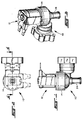
- valve assembly of the present invention is indicated generally at 10 and includes a solenoid actuator indicated generally at 12 which is attached to a body 14 having an inlet passage 16 communicating with a valving chamber 18 which has formed therein a valve seat 20 which communicates with an outlet passage 22 formed in an outlet fitting 24.
- Inlet passage 16 preferably includes a resiliently compressible flow control washer 26 and a retainer 28 and filter screen 30 which is retained by an inlet fitting 32 secured to the body by mounting bracket 34 and sealed thereagainst by a resilient seal ring 36.
- a moveable valve member preferably a flexible diaphragm 38 with a thickened center portion 40 comprising a valving pad is disposed in the valving chamber 18 and the pad 40 is moveable for contacting or opening and closing against valve seat 20.
- the pad portion 40 of diaphragm 38 has a rigid insert 42 received therethrough which has formed therein a pilot valve seat 44 which communicates with outlet passage 22 through a reduced diameter pilot passage 43.
- a pilot valving member 46 is disposed to seat against the valve seat 44 and is retained on the end of a ferromagnetic armature 48 which is slidably disposed in a tubular guide 50 formed of nonmagnetic material preferably thermoplastic material; and, armature 48 is biased into contact with the valve seat 44 by a spring 52 which is registered against the undersurface of the closed upper end of guide 50.
- the lower end of guide 50 has an enlarged diameter flange or bell mouth portion 54 integrally formed thereon which is received in body 14 and seals the outer peripheral rim of diaphragm 38 in the body.
- annular retaining member or ring 56 which, in the presently preferred practice is formed of thermoplastic material as is body 14; and, ring 56 is preferably secured to the body by weldment such as by spin welding.
- the solenoid coil assembly 12 is shown as including an encapsulated coil 58 having electrical terminals 60, 62 for external electrical connection thereto which terminals 60, 62 are oriented in spaced parallel relationship and extended generally right angles to the axis of the coil.
- the coil is denoted by reference numeral 64 in FIG. 4.
- a ferromagnetic pole frame 66 is disposed about the coil and is preferably formed by two right angle members having interlocking tabs 68 formed in diagonally opposite corners of the frame formed thereby.
- the pole frame 66 has formed integrally therewith tubular flanges 70, 72 which extend inwardly of the coil from the axially opposite ends thereof and which form an air gap therebetween.
- the armature guide has at least one, and preferably a plurality, of positionally engagement surfaces formed thereon which in the presently preferred practice comprise a plurality of teeth 74 spaced peripherally about the flange 54.
- the lower portion or rim 76 of the encapsulation 58 of coil assembly 12 has a pair of oppositely disposed slots 78 formed for receiving therethrough the lower cross member of the pole frame 66.
- the remaining portion of the rim 76 of the coil encapsulation has corresponding engagement surfaces 78 formed on the inner periphery thereof and which comprise teeth 80 which interdigitate with teeth 74 on the armature guide.
- the upper end of the armature guide tube 50 has at least one and preferably a plurality of snap engaging surfaces comprising tabs 82 formed thereon which are adapted to be resiliently radially compressed for assembly of the interior of the pole tubes 70, 72 thereover.
- the upper end of the guide tube extends through the pole tubes and the tabs 82 are permitted to deform slightly radially inwardly during assembly and return to their undeformed position as shown in FIG. 4 to retain the coil assembly 12 onto the armature guide tube 50.
- the coil assembly 12 is axially assembled onto the armature guide tube 50, the coil is rotationally positioned to the desired orientation of the terminals 60, 62 and the teeth 74, 80 are engaged as the coil is assembled axially onto the guide tube 50 and is retained axially thereon by tabs 82 and is thus rotationally locked in the desired position by the teeth 74, 80.
- the present invention thus provides a unique and novel way of orienting the solenoid coil with respect to a valve body of a solenoid operated valve upon assembly of the coil over the armature guide tube attached to the body and permits the coil to be oriented in any rotational position desired and secured in the selected position by engagement of corresponding engaging surfaces provided on the interior of the coil assembly encapsulation and the exterior of the armature guide.
- the engaging surfaces are a plurality of spaced peripheral teeth; however, it will be understood that the engagement surfaces may comprise any convenient shape, as for example, a single notch and projecting lug or polygonally-shaped interengaging surfaces or any other desired geometrical configuration.
Applications Claiming Priority (2)
| Application Number | Priority Date | Filing Date | Title |
|---|---|---|---|
| US08/741,458 US5941502A (en) | 1996-10-31 | 1996-10-31 | Electric valve assembly and method of making same |
| US741458 | 1996-10-31 |
Publications (1)
| Publication Number | Publication Date |
|---|---|
| EP0840048A1 true EP0840048A1 (de) | 1998-05-06 |
Family
ID=24980795
Family Applications (1)
| Application Number | Title | Priority Date | Filing Date |
|---|---|---|---|
| EP97118678A Withdrawn EP0840048A1 (de) | 1996-10-31 | 1997-10-28 | Elektrische Ventilanordnung und Verfahren zu ihrer Herstellung |
Country Status (5)
| Country | Link |
|---|---|
| US (1) | US5941502A (de) |
| EP (1) | EP0840048A1 (de) |
| JP (1) | JPH10132127A (de) |
| CA (1) | CA2217786A1 (de) |
| MX (1) | MX9708353A (de) |
Cited By (6)
| Publication number | Priority date | Publication date | Assignee | Title |
|---|---|---|---|---|
| WO2000077427A3 (en) * | 1999-06-14 | 2001-04-19 | Siemens Canada Ltd | Canister purge valve for high regeneration airflow |
| WO2007065776A1 (de) * | 2005-12-08 | 2007-06-14 | Robert Bosch Gmbh | Zweistufiges ventil zum steuern von fluiden |
| CN102568739A (zh) * | 2010-12-20 | 2012-07-11 | 罗伯特绍控制器公司 | 用于直动阀的具有阶梯状导管的螺线管 |
| ITTO20111148A1 (it) * | 2011-12-14 | 2013-06-15 | Elbi Int Spa | Valvola pilota a solenoide per una valvola idraulica, particolarmente per apparecchi elettrodomestici |
| WO2020035836A1 (en) | 2018-08-17 | 2020-02-20 | Bermad Cs Ltd. | Pilot valve assembly with orientation adjustment |
| IT202100025688A1 (it) * | 2021-10-07 | 2023-04-07 | Bitron Spa | Alloggiamento per valvole elettromagnetiche, elemento tubolare e relativa valvola elettromagnetica. |
Families Citing this family (16)
| Publication number | Priority date | Publication date | Assignee | Title |
|---|---|---|---|---|
| AT409890B (de) | 2000-09-27 | 2002-12-27 | Hoerbiger Micro Fluid Gmbh | Fluidventil |
| US6718968B2 (en) * | 2001-12-06 | 2004-04-13 | Modine Manufacturing Company | Enclosure for an infrared heater |
| US7040596B2 (en) * | 2002-11-29 | 2006-05-09 | Keihin Corporation | Solenoid valve for fuel cell |
| US7080817B2 (en) * | 2004-02-17 | 2006-07-25 | Y. Stern Engineering (1989) Ltd. | Electromagnetic valve |
| JP2006153218A (ja) * | 2004-11-30 | 2006-06-15 | Keihin Corp | 燃料電池用電磁弁 |
| JP4487845B2 (ja) * | 2005-05-02 | 2010-06-23 | 株式会社デンソー | 電磁弁 |
| JP4807287B2 (ja) * | 2006-10-06 | 2011-11-02 | 株式会社デンソー | 電磁アクチュエータ |
| ATE474167T1 (de) * | 2007-08-03 | 2010-07-15 | Georg Fischer Wavin Ag | Ventilanordnung mit drehmomentbegrenzer |
| DE102009050564B4 (de) | 2009-10-23 | 2022-10-13 | Svm Magnet Schultz Verwaltungs-Gmbh & Co. Kg | Befestigung für Elektromagneten |
| US10544874B2 (en) * | 2011-01-04 | 2020-01-28 | Robertshaw Controls Company | Coil capture apparatus and pilot operated water valve incorporating same |
| US20150247584A1 (en) * | 2014-03-03 | 2015-09-03 | Brent Richard SINGLEY | Flood prevention device |
| US11112025B2 (en) | 2017-03-30 | 2021-09-07 | Robertshaw Controls Company | Water valve guide tube with integrated weld ring and water valve incorporating same |
| CN107725786B (zh) * | 2017-09-29 | 2024-04-26 | 宁波捷尔天电气有限公司 | 一种安全先导电磁阀 |
| WO2019079426A1 (en) * | 2017-10-17 | 2019-04-25 | Automotive Technologies International, Inc. | HIGH SPEED VALVE |
| US20220213975A1 (en) * | 2019-09-23 | 2022-07-07 | Jiangmen Tiandi Electrical Appliance Co., Ltd | Water inlet solenoid valve capable of improving electromagnetic attraction and implementing method therefor |
| CN112539292B (zh) * | 2019-09-23 | 2022-02-11 | 江门市甜的电器有限公司 | 一种可提升电磁吸力的进水电磁阀及实现方法 |
Citations (4)
| Publication number | Priority date | Publication date | Assignee | Title |
|---|---|---|---|---|
| US4817914A (en) * | 1987-12-23 | 1989-04-04 | Eaton Corporation | Electromagnetic valve assembly |
| US5094264A (en) * | 1990-11-13 | 1992-03-10 | Borg-Warner Automotive Electronic & Mechanical Systems Corporation | Electromechanical solenoid valve with ratchet system for positioning the coil assembly |
| EP0655573A1 (de) * | 1993-11-24 | 1995-05-31 | Parker-Hannifin Corporation | Elektromagnetisch betätigtes Ventil |
| EP0685671A1 (de) * | 1994-05-31 | 1995-12-06 | Daewoo Electronics Co., Ltd | Fluidventil |
Family Cites Families (6)
| Publication number | Priority date | Publication date | Assignee | Title |
|---|---|---|---|---|
| US3011751A (en) * | 1957-03-18 | 1961-12-05 | Delany Realty Corp | Electrically operated flush valve |
| US3154285A (en) * | 1962-06-07 | 1964-10-27 | Houie Omer | Fuel derichment valve |
| IT986479B (it) * | 1973-06-18 | 1975-01-30 | Marocco A | Perfezionamenti nelle elettroval vole differenziali per il control lo di fluidi |
| JP2742792B2 (ja) * | 1988-06-28 | 1998-04-22 | 清原 まさ子 | 電磁制御装置 |
| US5299592A (en) * | 1993-01-08 | 1994-04-05 | Eaton Corporation | High pressure relief system |
| US5358215A (en) * | 1993-06-25 | 1994-10-25 | Borg-Warner Automotive, Inc. | Encapsulated solenoid operated valve assembly |
-
1996
- 1996-10-31 US US08/741,458 patent/US5941502A/en not_active Expired - Lifetime
-
1997
- 1997-10-28 EP EP97118678A patent/EP0840048A1/de not_active Withdrawn
- 1997-10-29 CA CA002217786A patent/CA2217786A1/en not_active Abandoned
- 1997-10-30 MX MX9708353A patent/MX9708353A/es not_active IP Right Cessation
- 1997-10-31 JP JP9300079A patent/JPH10132127A/ja active Pending
Patent Citations (4)
| Publication number | Priority date | Publication date | Assignee | Title |
|---|---|---|---|---|
| US4817914A (en) * | 1987-12-23 | 1989-04-04 | Eaton Corporation | Electromagnetic valve assembly |
| US5094264A (en) * | 1990-11-13 | 1992-03-10 | Borg-Warner Automotive Electronic & Mechanical Systems Corporation | Electromechanical solenoid valve with ratchet system for positioning the coil assembly |
| EP0655573A1 (de) * | 1993-11-24 | 1995-05-31 | Parker-Hannifin Corporation | Elektromagnetisch betätigtes Ventil |
| EP0685671A1 (de) * | 1994-05-31 | 1995-12-06 | Daewoo Electronics Co., Ltd | Fluidventil |
Cited By (11)
| Publication number | Priority date | Publication date | Assignee | Title |
|---|---|---|---|---|
| WO2000077427A3 (en) * | 1999-06-14 | 2001-04-19 | Siemens Canada Ltd | Canister purge valve for high regeneration airflow |
| WO2007065776A1 (de) * | 2005-12-08 | 2007-06-14 | Robert Bosch Gmbh | Zweistufiges ventil zum steuern von fluiden |
| US7954511B2 (en) | 2005-12-08 | 2011-06-07 | Robert Bosch Gmbh | Two-stage valve for controlling fluids |
| CN102568739A (zh) * | 2010-12-20 | 2012-07-11 | 罗伯特绍控制器公司 | 用于直动阀的具有阶梯状导管的螺线管 |
| ITTO20111148A1 (it) * | 2011-12-14 | 2013-06-15 | Elbi Int Spa | Valvola pilota a solenoide per una valvola idraulica, particolarmente per apparecchi elettrodomestici |
| WO2013088364A1 (en) * | 2011-12-14 | 2013-06-20 | Elbi International S.P.A. | Solenoid pilot valve for a hydraulic valve, in particular for household appliances |
| US9366358B2 (en) | 2011-12-14 | 2016-06-14 | Elbi International S.P.A. | Solenoid pilot valve for a hydraulic valve, in particular for household appliances |
| WO2020035836A1 (en) | 2018-08-17 | 2020-02-20 | Bermad Cs Ltd. | Pilot valve assembly with orientation adjustment |
| EP3837461A4 (de) * | 2018-08-17 | 2021-09-01 | Bermad CS Ltd. | Pilotventilanordnung mit orientierungseinstellung |
| IT202100025688A1 (it) * | 2021-10-07 | 2023-04-07 | Bitron Spa | Alloggiamento per valvole elettromagnetiche, elemento tubolare e relativa valvola elettromagnetica. |
| WO2023057941A1 (en) * | 2021-10-07 | 2023-04-13 | Bitron S.P.A | Housing for electromagnetic valves, tubular element and related electromagnetic valve. |
Also Published As
| Publication number | Publication date |
|---|---|
| CA2217786A1 (en) | 1998-04-30 |
| US5941502A (en) | 1999-08-24 |
| JPH10132127A (ja) | 1998-05-22 |
| MX9708353A (es) | 1998-04-30 |
Similar Documents
| Publication | Publication Date | Title |
|---|---|---|
| US5941502A (en) | Electric valve assembly and method of making same | |
| MXPA97008353A (en) | Electrical valve assembly and method of doing | |
| US4728916A (en) | Solenoid operated fluid control valve | |
| CN100523570C (zh) | 防流体电磁线圈作动阀 | |
| JP4083244B2 (ja) | 燃料噴射弁 | |
| US4697608A (en) | Electromagnetic valve assembly | |
| US4981155A (en) | Electrically operated valve assembly | |
| CA1317583C (en) | Electrically operated valve assembly | |
| EP0904487A1 (de) | Kraftausgeglichenes geräuschemissionsregelventil | |
| EP3259510B1 (de) | Solenoidvorrichtung | |
| US3459404A (en) | Solenoid valve | |
| US6792975B2 (en) | Pulse-width modulated solenoid valve including axial stop spool valve | |
| US5582205A (en) | Filtering flow in a valve | |
| CA2040568C (en) | Diaphragm actuated valve assembly | |
| US11721465B2 (en) | Solenoid apparatus and methods of assembly | |
| US3263959A (en) | Solenoid valve | |
| US20020096655A1 (en) | Canister purge valve for high regeneration airflow | |
| US5785394A (en) | Solenoid assembly for anti-lock braking system | |
| EP0961897B1 (de) | Verfahren und apparat zum befestigen einer versorgungsleitung an einem elektromagnetventil | |
| JPH0493004A (ja) | ソレノイド装置 | |
| CN217762203U (zh) | 一种电控燃气阀 | |
| JP2006220068A (ja) | 燃料噴射弁とコネクタとの接続構造 | |
| JPH0542290Y2 (de) | ||
| JPH09329262A (ja) | ソレノイドバルブおよびコネクタ | |
| CN111853318A (zh) | 阀芯驱动装置 |
Legal Events
| Date | Code | Title | Description |
|---|---|---|---|
| PUAI | Public reference made under article 153(3) epc to a published international application that has entered the european phase |
Free format text: ORIGINAL CODE: 0009012 |
|
| AK | Designated contracting states |
Kind code of ref document: A1 Designated state(s): AT BE CH DE DK ES FI FR GB GR IE IT LI LU MC NL PT SE |
|
| AX | Request for extension of the european patent |
Free format text: AL;LT;LV;RO;SI |
|
| K1C3 | Correction of patent application (complete document) published |
Effective date: 19980506 |
|
| AKX | Designation fees paid | ||
| RBV | Designated contracting states (corrected) | ||
| STAA | Information on the status of an ep patent application or granted ep patent |
Free format text: STATUS: THE APPLICATION IS DEEMED TO BE WITHDRAWN |
|
| 18D | Application deemed to be withdrawn |
Effective date: 19981107 |