EP0840003B1 - Kraftstoffeinspritzvorrichtung - Google Patents
Kraftstoffeinspritzvorrichtung Download PDFInfo
- Publication number
- EP0840003B1 EP0840003B1 EP97308457A EP97308457A EP0840003B1 EP 0840003 B1 EP0840003 B1 EP 0840003B1 EP 97308457 A EP97308457 A EP 97308457A EP 97308457 A EP97308457 A EP 97308457A EP 0840003 B1 EP0840003 B1 EP 0840003B1
- Authority
- EP
- European Patent Office
- Prior art keywords
- valve
- injector
- needle
- bore
- control
- Prior art date
- Legal status (The legal status is an assumption and is not a legal conclusion. Google has not performed a legal analysis and makes no representation as to the accuracy of the status listed.)
- Expired - Lifetime
Links
Images


Classifications
-
- F—MECHANICAL ENGINEERING; LIGHTING; HEATING; WEAPONS; BLASTING
- F02—COMBUSTION ENGINES; HOT-GAS OR COMBUSTION-PRODUCT ENGINE PLANTS
- F02M—SUPPLYING COMBUSTION ENGINES IN GENERAL WITH COMBUSTIBLE MIXTURES OR CONSTITUENTS THEREOF
- F02M59/00—Pumps specially adapted for fuel-injection and not provided for in groups F02M39/00 -F02M57/00, e.g. rotary cylinder-block type of pumps
- F02M59/20—Varying fuel delivery in quantity or timing
- F02M59/36—Varying fuel delivery in quantity or timing by variably-timed valves controlling fuel passages to pumping elements or overflow passages
- F02M59/366—Valves being actuated electrically
-
- F—MECHANICAL ENGINEERING; LIGHTING; HEATING; WEAPONS; BLASTING
- F02—COMBUSTION ENGINES; HOT-GAS OR COMBUSTION-PRODUCT ENGINE PLANTS
- F02M—SUPPLYING COMBUSTION ENGINES IN GENERAL WITH COMBUSTIBLE MIXTURES OR CONSTITUENTS THEREOF
- F02M47/00—Fuel-injection apparatus operated cyclically with fuel-injection valves actuated by fluid pressure
- F02M47/02—Fuel-injection apparatus operated cyclically with fuel-injection valves actuated by fluid pressure of accumulator-injector type, i.e. having fuel pressure of accumulator tending to open, and fuel pressure in other chamber tending to close, injection valves and having means for periodically releasing that closing pressure
- F02M47/027—Electrically actuated valves draining the chamber to release the closing pressure
-
- F—MECHANICAL ENGINEERING; LIGHTING; HEATING; WEAPONS; BLASTING
- F02—COMBUSTION ENGINES; HOT-GAS OR COMBUSTION-PRODUCT ENGINE PLANTS
- F02M—SUPPLYING COMBUSTION ENGINES IN GENERAL WITH COMBUSTIBLE MIXTURES OR CONSTITUENTS THEREOF
- F02M57/00—Fuel-injectors combined or associated with other devices
- F02M57/02—Injectors structurally combined with fuel-injection pumps
Definitions
- This invention relates to an injector arrangement for use in supplying fuel, under pressure, to the cylinders of an internal combustion engine.
- this invention relates to an injector arrangement in which the injector has a respective pump associated therewith, for example a pump/injector or a long pipe arrangement in which the injector is connected to its pump by a pipe.
- a known pump/injector arrangement comprises a plunger reciprocable within a bore provided in a housing to pressurize fuel located within the bore.
- the bore communicates with a fuel pressure actuated injector such that once the fuel pressure within the bore exceeds a predetermined level, the injector opens thus fuel injection commences.
- a pressure control valve which communicates with the bore, and an injection control valve which controls the pressure applied to a control chamber defined, in part, by a surface of a needle of the injector to control movement of the needle.
- the pressure control valve remains open during initial inward movement of the plunger. Subsequently, the pressure control valve is closed, further inward movement of the plunger pressurizing the fuel within the bore.
- the injection control valve is actuated to connect the control chamber to a low pressure drain thus permitting movement of the needle away from its seating to commence injection.
- EP-A-0240354 discloses such an arrangement in which the pressure control valve and the injection control valve are operated by separate actuators.
- GB-A- 2 298 025 discloses an injector with a pressure control valve and a needle control valve operated by a single solenoid. Accordingly, the actuator arrangements are only partly individual and only individually operable under certain conditions.
- the pressure control valve and injection control valve are actuated by a single electromagnetic actuator. Such arrangements are advantageous in that fewer electrical connections to the injector are required than where the valves are controlled by independent actuators.
- One arrangement including a single actuator includes an injection control valve in which the valve member includes an axially extending passage forming part of the delivery line through which fuel is supplied towards the injector seating.
- the valve member needs to be relatively large in order to provide a sufficient wall thickness to withstand the fuel pressure therein.
- an injector arrangement comprising a pump including a bore within which a pumping plunger is reciprocable, and an injector including pressure control valve arranged to control communication between the bore and a low pressure reservoir, an injector needle engageable with a seating, the needle being resiliently biased into engagement with the seating, a control chamber arranged such that the fuel pressure therein urges the needle towards its seating, a needle control valve arranged to control communication between the bore and the control chamber and between the control chamber and a low pressure drain, and individual actuator arrangements for actuating the pressure control valve and needle control valve independently of one another, wherein the needle control valve comprises a valve member slidable within a bore, an end of the valve member being sealingly engageable with a surface extending in a plane normal to the axis of the valve member to close a port communicating with the low pressure drain.
- Such an arrangement is advantageous in that reliable control of the valves may be achieved relatively easily. Further, by providing the drain port substantially coaxially with the control valve member, the provision of a delivery line extending along the axis of the control valve member, as in a known arrangement, can be avoided.
- control valve member is engageable with a surface extending in a plane normal to the axis of the valve member rather than with a seating coaxial therewith increases the tolerance to manufacturing inaccuracies.
- the pump and injector may be combined to form a pump/injector, or may be spaced apart from one another, a pipe being arranged to transfer fuel from the pump to the injector.
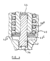
- the fuel injector illustrated in Figures 1 and 2 comprises a multi-part housing 10 including a housing part 11 having a bore 12 formed therein.
- a plunger 14 is reciprocable within the bore under the action of a cam arrangement, a return spring 16 being provided in order to withdraw the plunger 14 from the bore 12.
- the bore 12 communicates through a passage 18 with a pressure control spill valve 20 which controls communication between the passage 18 and a low pressure drain 22.
- the spill valve 20 comprises an electromagnetically operated valve including an actuator 24 the armature of which is connected to a valve member 26 which includes a region 26 a of enlarged diameter which is engageable with a seating 28 located so that when the enlarged region 26 a engages the seating 28 communication between the passage 18 and the low pressure drain 22 is not permitted, movement of the enlarged region 26 a away from its seating permitting such communication.
- a spring 30 is located so as to bias the valve member 26 towards a position in which the enlarged region 26 a thereof is spaced from its seating 28, energization of the actuator 24 moving the valve member 26 against the action of the spring 30 to break communication between the passage 18 and low pressure drain 22.
- the multi-part housing 10 further comprises a nozzle body 32 defining a bore within which a valve needle 34 is slidable, the valve needle 34 being engageable with a seating in order to control flow of fuel towards one or more outlet apertures (not shown) provided in an end of the nozzle body 32.
- the nozzle body 32 abuts a distance piece 36 which includes a through bore coaxial with the bore provided in the nozzle body 32, the through bore of the distance piece 36 including a region of enlarged diameter.
- a first valve housing 38 abuts the end of the distance piece 36 remote from the nozzle body 32, the first valve housing 38 including a projection 38 a which extends within the enlarged diameter region of the through bore of the distance piece 36, the first valve housing 38 and distance piece 36 together defining a spring chamber within which a spring 40 is located.
- the spring 40 is engaged between the first valve housing 38 and a spring abutment member 42 which abuts an end of the valve needle 34.
- the projection 38 a includes a blind bore within which a projection 42 a forming part of the abutment member 42 is slidable, the bore and projection 42 a together defining a control chamber 44 which communicates through a passage 46 with an end face of the first valve housing 38 facing away from the distance piece 36.
- the face of the first valve housing 38 facing away from the distance piece 36 abuts a second valve housing 48 which is provided with a through bore within which a valve member 50 is slidable.
- the valve member 50 is secured to an armature 52 which is moveable under the influence of a stator 54 located within a stator housing 56, the stator housing 56 being located between the second valve housing 48 and the housing part 11.
- a cap nut 58 is in screw-threaded engagement with the housing part 11, the cap nut 58 securing the nozzle body 32, distance piece 36, first and second valve housings 38, 48 and stator housing 56 to the housing part 11.
- stator housing 56 The housing part 11, stator housing 56, first and second valve housings 38, 48 distance piece 36 and nozzle body 32 are each provided with drillings which together form a delivery line 60 permitting fuel to flow from the bore 12 to the bore provided in the nozzle body 32 to act against appropriately orientated thrust surfaces of the needle 34 to urge the needle 34 away from its seating.
- a drilling 62 is provided in the second valve housing 48, the drilling 62 providing a communication path between the passage 46 and the supply line 60. As shown most clearly in Figure 2, the drilling 62 communicates with the through bore of the second valve housing 48, the drilling 62 being located such that the part of the through bore at the end face of the second valve housing 48 is of non-circular shape, the drilling 62 breaking into the through bore at the end face of the second valve housing.
- the through bore is shaped so as to define a seating located such that when an enlarged diameter region 50 a of the valve member 50 engages the seating, communication between the passage 46 and delivery line 60 is broken, movement of the enlarged region 50 a away from its seating permitting such communication thus resulting in the fuel pressure within the control chamber 44 being substantially equal to that within the delivery line 60.
- the force acting on the valve needle 34 urging the valve needle 34 into engagement with its seating due to the pressure within the control chamber 44 and due to the action of the spring 40 is greater than the forces urging the valve needle 34 away from its seating due to the action of fuel against the thrust surfaces of the valve needle 34.
- the valve needle 34 therefore occupies a position in which it engages its seating in such circumstances.
- valve member 50 An end of the valve member 50 is sealingly engageable with a surface of the first valve housing 38 facing the second valve housing 48, such sealing engagement breaking communication between the through bore of the second valve housing 48 and a drilling 64 provided in the first valve housing 38 substantially coaxially with the through bore of the second valve housing 48, the drilling 64 being arranged to communicate with a suitable low pressure drain through a suitable drain passage.
- the drain passage further communicates with the spring chamber thus movement of the spring abutment member 42, in use, does not result in significant pressurization of fuel within the spring chamber.
- a recess is conveniently provided in the end face of the valve member 50 facing the first valve housing 38, the recess being aligned with the drilling 64.
- valve member 50 In use, starting from the position illustrated in Figure 1, the valve member 50 is in engagement with the first valve housing 38 thus the fuel pressure within the control chamber 44 is substantially equal to that within the delivery line 60. As indicated hereinbefore, in such circumstances the valve needle 34 engages its seating thus injection does not take place.
- the plunger 14 is in its outermost position, the bore 12 being charged with fuel, and the valve 20 occupies a position in which communication between the passage 18 and low pressure drain 22 is permitted. From this position, the plunger 14 commences inward movement into the bore 12. Such movement results in fuel being displaced through the valve 20 to the low pressure drain 22.
- the actuator 24 of the valve 20 When it is determined that pressurization of the fuel within the bore 12 should commence, the actuator 24 of the valve 20 is energized resulting in movement of the valve member 26 thereof to bring the enlarged region 26 a into engagement with its seating thus terminating the flow of fuel from the bore 12 to the low pressure drain 22. It will be appreciated that continued inward movement of the plunger 14 therefore results in the pressure of fuel within the bore 12 increasing.
- the pressure of fuel applied to the thrust surfaces of the valve needle 34 and also the pressure of fuel applied to the control chamber 44 thus also increase.
- the communication between the control chamber 44 and the delivery line 60 ensures that a sufficiently high force is applied to the valve needle 34 during such pressurization to maintain the engagement between the valve needle 34 and seating thus injection does not commence.
- the stator 54 When injection is to be commenced, the stator 54 is energized to attract the armature 52 towards the stator against the action of a spring 68, the movement of the armature 52 resulting in movement of the valve member 50 to lift the end thereof away from the end face of the first valve housing 38 and to bring the enlarged region 50 a of the valve member 50 into engagement with its seating.
- Such movement of the valve member 50 breaks communication between the control chamber 44 and the delivery line 60 and instead permits communication between the control chamber 44 and the low pressure drain. The pressure within the control chamber 44 therefore falls.
- the reduced pressure within the control chamber 44 results in reduction in the force urging the valve needle 34 into engagement with its seating, and a point will be reached at which the pressure acting against the thrust surfaces of the valve needle 34 is sufficient to overcome the action of the spring 40 and fuel pressure within the control chamber 44 to lift the valve needle 34 away from its seating and hence permit fuel to flow past the seating of the nozzle body 32 to the outlet apertures and hence commence injection.
- the stator 54 is de-energized thus the armature 52 and valve member 50 return under the action of the spring 68 to the position shown in Figures 1 and 2.
- the control chamber 44 no longer communicates with the low pressure drain and instead communicates with the supply passage 60.
- the fuel pressure within the control chamber 44 therefore increases, and a point will be reached at which the fuel pressure within the control chamber 44 is sufficient to return the valve needle 34 towards its seating thus terminating injection.
- the valve 20 is de-energized thus the valve member 26 thereof moves under the action of the spring 30 to a position in which fuel from the bore 12 is able to flow through the valve 20 to the low pressure drain 22.
- the fuel pressure within the bore 12 therefore falls.
- Figure 3 illustrates an arrangement which is similar to that of Figures 1 and 2, but in which the spring abutment member 42 includes a separate rather than integral projection 42 a .
- the provision of an integral projection 42a has the advantage that the spring abutment member 42 is guided, but the disadvantage that the spring abutment member 42 is of relatively complex shape. There may, therefore, be circumstances in which it is preferred to use the arrangement of Figure 3 in which the projection is not integral with the spring abutment member 42.
- Figure 4 illustrates a further alternative in which the projection 42a is integral with a part of the spring abutment member 42 which engages the valve needle, the spring abutment member 42 including a separate annular abutment member 42b which is engageable with a shoulder 42c provided on the spring abutment member 42, the annular abutment member 42b being arranged to engage the spring 40, in use.
- the injection control valve is of a relatively simple form, and as the supply of fuel to the injector does not pass through the injection control valve, the injection control valve merely being used to control the pressure within the control chamber 44, the valve member 50 of the pressure control valve may be of relatively small diameter. Further, as the pressure control valve and injection control valve are controlled using separate actuators, reliable control of the valves may be achieved relatively easily.
Landscapes
- Engineering & Computer Science (AREA)
- Chemical & Material Sciences (AREA)
- Combustion & Propulsion (AREA)
- Mechanical Engineering (AREA)
- General Engineering & Computer Science (AREA)
- Physics & Mathematics (AREA)
- Fluid Mechanics (AREA)
- Fuel-Injection Apparatus (AREA)
Claims (10)
- Einspritzvorrichtung, die aufweist: eine Pumpe, die eine Bohrung (12) umfaßt, innerhalb der ein Pumpkolben (14) hin- und herbeweglich ist; und eine Einspritzdüse, die umfaßt: ein Druckregelventil (20), das angeordnet ist, um die Verbindung zwischen der Bohrung (12) und einem Niederdruckbehälter (22) zu regulieren; eine Düsennadel (34), die mit einem Sitz in Eingriff kommen kann, wobei die Nadel (34) mit dem Sitz elastisch in Eingriff vorgespannt werden kann; eine Regelungskammer (44), die so angeordnet ist, daß die Anwendung von Kraftstoff mit hohem Druck darauf die Nadel (34) in Richtung ihres Sitzes treibt; ein Nadelregelungsventil (50), das angeordnet ist, um die Verbindung zwischen der Bohrung (12) und der Regelungskammer (44) und zwischen der Regelungskammer (44) und einem Niederdruckauslaß (22) zu regulieren; und einzelne Betätigungselementanordnungen (24, 52, 54) für das Betätigen des Druckregelventils (20) und des Nadelregelungsventils (50) unabhängig voneinander, wobei das Nadelregelventil (50) ein Ventilelement (50) aufweist, das innerhalb einer Bohrung verschiebbar ist, wobei ein Ende des Ventilelementes (50) abdichtend mit einer Fläche in Eingriff kommen kann, die sich in einer Ebene senkrecht zur Achse des Ventilelementes (50) erstreckt, um eine Öffnung (64) zu schließen, die mit dem Niederdruckauslaß (22) in Verbindung steht.
- Einspritzvorrichtung nach Anspruch 1, bei der die Öffnung (64), die mit dem Niederdruckauslaß (22) in Verbindung steht, im allgemeinen koaxial mit dem Ventilelement (50) angeordnet ist.
- Einspritzvorrichtung nach Anspruch 1 oder Anspruch 2, bei der ein Teil (50a) des Ventilelementes (50), der vom Ende davon beabstandet ist, mit einem Sitz in Eingriff kommen kann, um die Verbindung zwischen der Bohrung (12) und der Regelungskammer (44) zu regulieren.
- Einspritzvorrichtung nach einem der vorhergehenden Ansprüche, die außerdem ein Widerlagerelement (42a) aufweist, das eine Fläche aufweist, die dem Kraftstoffdruck innerhalb der Regelungskammer (44) ausgesetzt ist, wobei das Widerlagerelement (42a) die Kraft infolge der Wirkung des Kraftstoffdruckes innerhalb der Regelungskammer (44) auf die Ventilnadel (34) überträgt.
- Einspritzvorrichtung nach Anspruch 4, die außerdem eine Feder (40) aufweist, die die Nadel (34) in Richtung ihres Sitzes elastisch vorspannt, wobei die Feder (40) mit einem Federwiderlager (42) in Eingriff kommt, das mit dem Widerlagerelement (42a) beweglich ist.
- Einspritzvorrichtung nach Anspruch 5, bei der das Federwiderlager (42) mit dem Widerlagerelement (42a) zusammenhängend ist.
- Einspritzdüse nach Anspruch 5, bei der das Widerlagerelement (42a) mit dem Federwiderlager (42) in Eingriff kommt, wobei die Kraft infolge des Kraftstoffdruckes innerhalb der Regelungskammer (44) auf die Ventilnadel (34) durch das Federwiderlager (42) übertragen wird.
- Einspritzvorrichtung nach Anspruch 5, bei der das Federwiderlager (42b) durch das Widerlagerelement (42) getragen wird.
- Einspritzvorrichtung nach einem der vorhergehenden Ansprüche, bei der die Einspritzdüse auf der Pumpe montiert ist.
- Einspritzvorrichtung nach einem der Ansprüche 1 bis 8, bei der die Pumpe und die Einspritzdüse voneinander beabstandet sind, wobei ein Rohr die Bohrung der Pumpe mit der Einspritzdüse verbindet.
Applications Claiming Priority (2)
| Application Number | Priority Date | Filing Date | Title |
|---|---|---|---|
| GBGB9622335.9A GB9622335D0 (en) | 1996-10-26 | 1996-10-26 | Injector arrangement |
| GB9622335 | 1996-10-26 |
Publications (2)
| Publication Number | Publication Date |
|---|---|
| EP0840003A1 EP0840003A1 (de) | 1998-05-06 |
| EP0840003B1 true EP0840003B1 (de) | 2003-01-08 |
Family
ID=10802009
Family Applications (1)
| Application Number | Title | Priority Date | Filing Date |
|---|---|---|---|
| EP97308457A Expired - Lifetime EP0840003B1 (de) | 1996-10-26 | 1997-10-23 | Kraftstoffeinspritzvorrichtung |
Country Status (6)
| Country | Link |
|---|---|
| US (1) | US5915623A (de) |
| EP (1) | EP0840003B1 (de) |
| JP (1) | JP4068195B2 (de) |
| DE (1) | DE69718275T2 (de) |
| ES (1) | ES2189927T3 (de) |
| GB (1) | GB9622335D0 (de) |
Cited By (2)
| Publication number | Priority date | Publication date | Assignee | Title |
|---|---|---|---|---|
| DE102005004069A1 (de) * | 2005-01-28 | 2006-08-03 | Volkswagen Mechatronic Gmbh & Co. Kg | Einspritzvorrichtung mit einer Dichtungsanordnung |
| DE102006061896A1 (de) | 2006-12-28 | 2008-07-03 | Robert Bosch Gmbh | Kraftstoffinjektor mit einer verbesserten Steuerung der Düsennadel |
Families Citing this family (24)
| Publication number | Priority date | Publication date | Assignee | Title |
|---|---|---|---|---|
| GB2336628A (en) * | 1998-04-24 | 1999-10-27 | Lucas Ind Plc | A fuel injector, for an I.C. engine, having a three way two position needle control valve |
| GB9820033D0 (en) * | 1998-09-16 | 1998-11-04 | Lucas Ind Plc | Fuel injector |
| GB9915118D0 (en) | 1999-06-30 | 1999-09-01 | Lucas Ind Plc | Fuel injector |
| DE19936667A1 (de) * | 1999-08-04 | 2001-02-22 | Bosch Gmbh Robert | Common-Rail-Injektor |
| DE19937713C1 (de) * | 1999-08-10 | 2001-03-15 | Siemens Ag | Steuerventilanordnung zum Einsatz in einem Kraftstoffinjektor für Verbrennungsmotoren |
| GB9923823D0 (en) | 1999-10-09 | 1999-12-08 | Lucas Industries Ltd | Fuel injector |
| DE19949527A1 (de) * | 1999-10-14 | 2001-04-19 | Bosch Gmbh Robert | Injektor für ein Kraftstoffeinspritzsystem für Brennkraftmaschinen mit in den Ventilsteuerraum ragender Düsennadel |
| GB0001766D0 (en) * | 2000-01-27 | 2000-03-15 | Delphi Tech Inc | Fuel injector |
| GB0107575D0 (en) * | 2001-03-27 | 2001-05-16 | Delphi Tech Inc | Control valve arrangement |
| DE10120804A1 (de) * | 2001-04-27 | 2002-11-07 | Bosch Gmbh Robert | Injektor zum Einspritzen von Kraftstoff mit sequentiellem Aufbau |
| GB0119218D0 (en) | 2001-08-07 | 2001-09-26 | Delphi Tech Inc | Fuel injector |
| US6439202B1 (en) | 2001-11-08 | 2002-08-27 | Cummins Inc. | Hybrid electronically controlled unit injector fuel system |
| DE10158659A1 (de) * | 2001-11-30 | 2003-06-12 | Bosch Gmbh Robert | Kraftstoffeinspritzeinrichtung für eine Brennkraftmaschine |
| DE10205218A1 (de) * | 2002-02-08 | 2003-10-30 | Bosch Gmbh Robert | Ventil zur Steuerung einer Verbindung in einem Hochdruckflüssigkeitssystem, insbesondere einer Kraftstoffeinspitzeinrichtung für eine Brennkraftmaschine |
| DE10212508A1 (de) | 2002-03-21 | 2003-10-02 | Bosch Gmbh Robert | Verfahren und Vorrichtung zur Steuerung der Kraftstoffzumessung in eine Brennkraftmaschine |
| DE10212509B4 (de) * | 2002-03-21 | 2013-03-21 | Robert Bosch Gmbh | Verfahren und Vorrichtung zur Steuerung der Kraftstoffzumessung in eine Brennkraftmaschine |
| GB0215490D0 (en) * | 2002-07-04 | 2002-08-14 | Delphi Tech Inc | Control valve arrangement |
| DE10344897A1 (de) | 2003-09-26 | 2005-04-21 | Bosch Gmbh Robert | Ventil zur Steuerung einer Verbindung in einem Hochdruckflüssigkeitssystem, insbesondere einer Kraftstoffeinspritzeinrichtung für eine Brennkraftmaschine |
| US7455243B2 (en) * | 2004-03-03 | 2008-11-25 | Caterpillar Inc. | Electronic unit injector with pressure assisted needle control |
| US7547000B2 (en) * | 2005-03-08 | 2009-06-16 | Caterpillar Inc. | Valve coupling system |
| US7255091B2 (en) * | 2005-05-31 | 2007-08-14 | Caterpillar, Inc. | Fuel injector control system and method |
| US7111613B1 (en) | 2005-05-31 | 2006-09-26 | Caterpillar Inc. | Fuel injector control system and method |
| US7111614B1 (en) | 2005-08-29 | 2006-09-26 | Caterpillar Inc. | Single fluid injector with rate shaping capability |
| US7520266B2 (en) * | 2006-05-31 | 2009-04-21 | Caterpillar Inc. | Fuel injector control system and method |
Family Cites Families (12)
| Publication number | Priority date | Publication date | Assignee | Title |
|---|---|---|---|---|
| CH669822A5 (de) * | 1986-02-12 | 1989-04-14 | Sulzer Ag | |
| JPH0759919B2 (ja) * | 1986-04-04 | 1995-06-28 | 日本電装株式会社 | デイ−ゼルエンジン用燃料噴射制御装置 |
| JPH07109181B2 (ja) * | 1986-12-05 | 1995-11-22 | 日本電装株式会社 | 内燃機関用燃料噴射装置 |
| JPH0196466A (ja) * | 1987-10-07 | 1989-04-14 | Honda Motor Co Ltd | 内燃機関用燃料噴射ノズル |
| US4993636A (en) * | 1988-03-04 | 1991-02-19 | Yamaha Hatsudoki Kabushiki Kaisha | High pressure fuel injection device for engine |
| DE3937917A1 (de) * | 1989-11-15 | 1991-05-16 | Man Nutzfahrzeuge Ag | Verfahren zum intermittierenden einspritzen von brennstoff in den brennraum einer brennkraftmaschine, sowie vorrichtung zur durchfuehrung dieses verfahrens |
| DE4115477C2 (de) * | 1990-05-17 | 2003-02-06 | Avl Verbrennungskraft Messtech | Einspritzdüse für eine Brennkraftmaschine |
| JP2712760B2 (ja) * | 1990-05-29 | 1998-02-16 | トヨタ自動車株式会社 | 燃料噴射弁 |
| GB9320798D0 (en) * | 1993-10-08 | 1993-12-01 | Lucas Ind Plc | Fuel injection nozzle |
| DE4336108C1 (de) * | 1993-10-22 | 1994-12-01 | Daimler Benz Ag | Magnetvenitl an einer für Brennkraftmaschinen vorgesehenen Kraftstoffeinspritzdüse |
| US5680988A (en) * | 1995-01-20 | 1997-10-28 | Caterpillar Inc. | Axial force indentation or protrusion for a reciprocating piston/barrel assembly |
| GB9508623D0 (en) * | 1995-04-28 | 1995-06-14 | Lucas Ind Plc | "Fuel injection nozzle" |
-
1996
- 1996-10-26 GB GBGB9622335.9A patent/GB9622335D0/en active Pending
-
1997
- 1997-10-22 US US08/955,676 patent/US5915623A/en not_active Expired - Lifetime
- 1997-10-23 ES ES97308457T patent/ES2189927T3/es not_active Expired - Lifetime
- 1997-10-23 DE DE69718275T patent/DE69718275T2/de not_active Expired - Lifetime
- 1997-10-23 EP EP97308457A patent/EP0840003B1/de not_active Expired - Lifetime
- 1997-10-27 JP JP29431397A patent/JP4068195B2/ja not_active Expired - Lifetime
Cited By (2)
| Publication number | Priority date | Publication date | Assignee | Title |
|---|---|---|---|---|
| DE102005004069A1 (de) * | 2005-01-28 | 2006-08-03 | Volkswagen Mechatronic Gmbh & Co. Kg | Einspritzvorrichtung mit einer Dichtungsanordnung |
| DE102006061896A1 (de) | 2006-12-28 | 2008-07-03 | Robert Bosch Gmbh | Kraftstoffinjektor mit einer verbesserten Steuerung der Düsennadel |
Also Published As
| Publication number | Publication date |
|---|---|
| EP0840003A1 (de) | 1998-05-06 |
| DE69718275T2 (de) | 2003-10-02 |
| GB9622335D0 (en) | 1996-12-18 |
| DE69718275D1 (de) | 2003-02-13 |
| ES2189927T3 (es) | 2003-07-16 |
| JPH10148167A (ja) | 1998-06-02 |
| US5915623A (en) | 1999-06-29 |
| JP4068195B2 (ja) | 2008-03-26 |
Similar Documents
| Publication | Publication Date | Title |
|---|---|---|
| EP0840003B1 (de) | Kraftstoffeinspritzvorrichtung | |
| EP0823550B1 (de) | Einspritzventil | |
| EP0889230B1 (de) | Kraftstoffeinspritzventil | |
| US6267306B1 (en) | Fuel injector including valve needle, injection control valve, and drain valve | |
| EP0878623B1 (de) | Kraftstoffeinspritzventil | |
| EP0823549B1 (de) | Einspritzventil | |
| EP0331200B1 (de) | Brennstoffeinspritzdüse | |
| US6651625B1 (en) | Fuel system and pump suitable for use therein | |
| US4899935A (en) | Valve support for accumulator type fuel injection nozzle | |
| EP0726390A1 (de) | Brennstoffsystem | |
| US6502555B1 (en) | Fuel injector | |
| US6405940B2 (en) | Fuel injector | |
| EP0987430B1 (de) | Brennstoffeinspritzventil | |
| EP1136692B1 (de) | Brennstoffeinspritzventil mit einem Steuerstab, gesteuert durch den Brennstoffdruck in einem Steuerraum | |
| EP0845791A2 (de) | Elektromagnetischer Betätiger | |
| EP0965750B1 (de) | Brennstoffeinspritzventil | |
| EP1065368A2 (de) | Kraftstoffeinspritzventil | |
| US20030019959A1 (en) | Fuel injection device for internal combustion engines | |
| JPH0429082Y2 (de) | ||
| EP0363996A1 (de) | Hochdruck-Brennstoffeinspritzgerät für Motoren | |
| EP1283355B1 (de) | Kraftstoffeinspritzventil | |
| GB2345741A (en) | Pressure balanced control valve |
Legal Events
| Date | Code | Title | Description |
|---|---|---|---|
| PUAI | Public reference made under article 153(3) epc to a published international application that has entered the european phase |
Free format text: ORIGINAL CODE: 0009012 |
|
| AK | Designated contracting states |
Kind code of ref document: A1 Designated state(s): DE ES FR GB IT |
|
| AX | Request for extension of the european patent |
Free format text: AL;LT;LV;RO;SI |
|
| 17P | Request for examination filed |
Effective date: 19981105 |
|
| AKX | Designation fees paid |
Free format text: DE ES FR GB IT |
|
| RBV | Designated contracting states (corrected) |
Designated state(s): DE ES FR GB IT |
|
| RAP1 | Party data changed (applicant data changed or rights of an application transferred) |
Owner name: CATERPILLAR INC. Owner name: LUCAS INDUSTRIES LIMITED |
|
| RAP1 | Party data changed (applicant data changed or rights of an application transferred) |
Owner name: CATERPILLAR INC. Owner name: DELPHI TECHNOLOGIES, INC. |
|
| 17Q | First examination report despatched |
Effective date: 20010212 |
|
| GRAG | Despatch of communication of intention to grant |
Free format text: ORIGINAL CODE: EPIDOS AGRA |
|
| GRAG | Despatch of communication of intention to grant |
Free format text: ORIGINAL CODE: EPIDOS AGRA |
|
| GRAG | Despatch of communication of intention to grant |
Free format text: ORIGINAL CODE: EPIDOS AGRA |
|
| GRAH | Despatch of communication of intention to grant a patent |
Free format text: ORIGINAL CODE: EPIDOS IGRA |
|
| GRAH | Despatch of communication of intention to grant a patent |
Free format text: ORIGINAL CODE: EPIDOS IGRA |
|
| GRAA | (expected) grant |
Free format text: ORIGINAL CODE: 0009210 |
|
| AK | Designated contracting states |
Kind code of ref document: B1 Designated state(s): DE ES FR GB IT |
|
| REG | Reference to a national code |
Ref country code: GB Ref legal event code: FG4D |
|
| REF | Corresponds to: |
Ref document number: 69718275 Country of ref document: DE Date of ref document: 20030213 Kind code of ref document: P |
|
| ET | Fr: translation filed | ||
| REG | Reference to a national code |
Ref country code: ES Ref legal event code: FG2A Ref document number: 2189927 Country of ref document: ES Kind code of ref document: T3 |
|
| PGFP | Annual fee paid to national office [announced via postgrant information from national office to epo] |
Ref country code: GB Payment date: 20031006 Year of fee payment: 7 |
|
| PGFP | Annual fee paid to national office [announced via postgrant information from national office to epo] |
Ref country code: ES Payment date: 20031020 Year of fee payment: 7 |
|
| PLBE | No opposition filed within time limit |
Free format text: ORIGINAL CODE: 0009261 |
|
| STAA | Information on the status of an ep patent application or granted ep patent |
Free format text: STATUS: NO OPPOSITION FILED WITHIN TIME LIMIT |
|
| 26N | No opposition filed |
Effective date: 20031009 |
|
| PG25 | Lapsed in a contracting state [announced via postgrant information from national office to epo] |
Ref country code: GB Free format text: LAPSE BECAUSE OF NON-PAYMENT OF DUE FEES Effective date: 20041023 |
|
| PG25 | Lapsed in a contracting state [announced via postgrant information from national office to epo] |
Ref country code: ES Free format text: LAPSE BECAUSE OF NON-PAYMENT OF DUE FEES Effective date: 20041025 |
|
| GBPC | Gb: european patent ceased through non-payment of renewal fee |
Effective date: 20041023 |
|
| PG25 | Lapsed in a contracting state [announced via postgrant information from national office to epo] |
Ref country code: IT Free format text: LAPSE BECAUSE OF NON-PAYMENT OF DUE FEES Effective date: 20051023 |
|
| REG | Reference to a national code |
Ref country code: ES Ref legal event code: FD2A Effective date: 20041025 |
|
| REG | Reference to a national code |
Ref country code: FR Ref legal event code: TQ Owner name: DELPHI TECHNOLOGIES HOLDING S.A.R.L., LU Effective date: 20111020 |
|
| REG | Reference to a national code |
Ref country code: DE Ref legal event code: R082 Ref document number: 69718275 Country of ref document: DE Representative=s name: LEONHARD & PARTNER PATENTANWAELTE, DE |
|
| REG | Reference to a national code |
Ref country code: DE Ref legal event code: R082 Ref document number: 69718275 Country of ref document: DE Representative=s name: LEONHARD & PARTNER PATENTANWAELTE, DE Effective date: 20140701 Ref country code: DE Ref legal event code: R081 Ref document number: 69718275 Country of ref document: DE Owner name: DELPHI INTERNATIONAL OPERATIONS LUXEMBOURG S.A, LU Free format text: FORMER OWNERS: CATERPILLAR INC., PEORIA, ILL., US; DELPHI TECHNOLOGIES HOLDING S.A.R.L., BASCHARAGE, LU Effective date: 20140701 Ref country code: DE Ref legal event code: R081 Ref document number: 69718275 Country of ref document: DE Owner name: CATERPILLAR INC., PEORIA, US Free format text: FORMER OWNERS: CATERPILLAR INC., PEORIA, ILL., US; DELPHI TECHNOLOGIES HOLDING S.A.R.L., BASCHARAGE, LU Effective date: 20140701 Ref country code: DE Ref legal event code: R081 Ref document number: 69718275 Country of ref document: DE Owner name: DELPHI INTERNATIONAL OPERATIONS LUXEMBOURG S.A, LU Free format text: FORMER OWNER: CATERPILLAR INC., DELPHI TECHNOLOGIES HOLDING S.A, , LU Effective date: 20140701 Ref country code: DE Ref legal event code: R081 Ref document number: 69718275 Country of ref document: DE Owner name: CATERPILLAR INC., PEORIA, US Free format text: FORMER OWNER: CATERPILLAR INC., DELPHI TECHNOLOGIES HOLDING S.A, , LU Effective date: 20140701 |
|
| REG | Reference to a national code |
Ref country code: FR Ref legal event code: TQ Owner name: DELPHI INTERNATIONAL OPERATIONS LUXEMBOURG S.A, LU Effective date: 20140826 Ref country code: FR Ref legal event code: TQ Owner name: CATERPILLAR INC., US Effective date: 20140826 |
|
| REG | Reference to a national code |
Ref country code: FR Ref legal event code: PLFP Year of fee payment: 19 |
|
| REG | Reference to a national code |
Ref country code: FR Ref legal event code: PLFP Year of fee payment: 20 |
|
| PGFP | Annual fee paid to national office [announced via postgrant information from national office to epo] |
Ref country code: FR Payment date: 20161025 Year of fee payment: 20 Ref country code: DE Payment date: 20161027 Year of fee payment: 20 |
|
| REG | Reference to a national code |
Ref country code: DE Ref legal event code: R071 Ref document number: 69718275 Country of ref document: DE |