EP0839304B1 - Distributor for a heating or cooling installation - Google Patents
Distributor for a heating or cooling installation Download PDFInfo
- Publication number
- EP0839304B1 EP0839304B1 EP96922329A EP96922329A EP0839304B1 EP 0839304 B1 EP0839304 B1 EP 0839304B1 EP 96922329 A EP96922329 A EP 96922329A EP 96922329 A EP96922329 A EP 96922329A EP 0839304 B1 EP0839304 B1 EP 0839304B1
- Authority
- EP
- European Patent Office
- Prior art keywords
- cone
- return
- restriction
- spindle
- hole
- Prior art date
- Legal status (The legal status is an assumption and is not a legal conclusion. Google has not performed a legal analysis and makes no representation as to the accuracy of the status listed.)
- Expired - Lifetime
Links
- 238000010438 heat treatment Methods 0.000 title claims abstract description 7
- 238000001816 cooling Methods 0.000 title claims abstract description 6
- 238000009434 installation Methods 0.000 title 1
- 238000005192 partition Methods 0.000 claims description 3
- 230000037431 insertion Effects 0.000 claims 2
- 238000003780 insertion Methods 0.000 claims 2
- 238000010586 diagram Methods 0.000 description 3
- 238000010276 construction Methods 0.000 description 2
- 230000004888 barrier function Effects 0.000 description 1
- 230000007423 decrease Effects 0.000 description 1
- 238000005315 distribution function Methods 0.000 description 1
- 238000007789 sealing Methods 0.000 description 1
- 239000000725 suspension Substances 0.000 description 1
Images

Classifications
-
- F—MECHANICAL ENGINEERING; LIGHTING; HEATING; WEAPONS; BLASTING
- F24—HEATING; RANGES; VENTILATING
- F24D—DOMESTIC- OR SPACE-HEATING SYSTEMS, e.g. CENTRAL HEATING SYSTEMS; DOMESTIC HOT-WATER SUPPLY SYSTEMS; ELEMENTS OR COMPONENTS THEREFOR
- F24D19/00—Details
- F24D19/0002—Means for connecting central heating radiators to circulation pipes
- F24D19/0004—In a one pipe system
- F24D19/0007—Comprising regulation means
Definitions
- the present invention relates to a distributor for a heating or cooling plant according to the preamble of patent claim 1.
- the flows through the smaller radiators are in practice too large. Too large flows mean, that the heat emission increases and this means, that small radiators in a loop emit more energy than they are designed to do. This also means, that e.g. a larger radiator close to the end of the loop will function under conditions, which it is not designed for, i.e. with a too low average temperatur and a too small heat emission. As to the climate in the house, a room with a smaller radiator will be too hot, whereas a room with a larger radiator will be too cold.
- US-A-3 618 855 relates to a radiator valve, in which the spindle is provided with a restriction cone. This cone is not controlled in any other way than through the spindle suspension in one of its ends, and consequently mounting variations, flow variations, vibrations etc. may occur.
- One object of the present invention is to considerably counter-act and to eliminate , if possible completely, the above-mentioned drawbacks. Another object is to accomplish this with simple yet reliable means. A further object of the invention is to further develop this technical field in various respects.
- the flow up to a radiator can be varied without influencing the total loop flow and consequently also not the conditions in the remaining radiators or other parts in a large flow system.
- a radiator valve is used, which is connected in parallel with the restriction of the distributor and the k-value of which e.g. and preferably is less than 0.80.
- an essential feature of the invention is that the restriction/ distribution function of the distributor is obtained by means of a control component, which comprises a polygonal, preferably triangular restriction cone.
- the design of the restriction cone results in a centering function of a spindle, also apart of the control component as well as the choking.
- the variation of the choking can be obtained by means of obliquely cut, suitably flat surfaces, which differ as to direction in relation to the cylindrical bypass flow through of the distributor housing.
- the distributor is provided with an interior, e.g. circular arc-shaped partition as well as the front value body of the spindle with a flange portion with a larger diameter , designed to choke the medium flows.
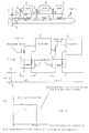
- a new single-tube system 1 according to the present invention is shown in its entirety and a similar conventional system 2 and also a forward feed tube 3, a return tube 4 and a bypass tube respectively as well as radiators 5, radiator valves 6 och distributors 7.
- Figs. 1, 2 and 3 are self-explanatory in combination with the introductory portion of the description.
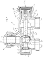
- the distributor according to the present invention in its entirety designated 7, comprises according to Fig. 4 a housing 8 having an axial through hole 9, the one end of which is designed as a return inlet 10 and to which laterally a return outlet 11, a feed inlet 12 and a feed outlet 13 are connected.
- the latter is an example provided with a sealing cone 14 and a pressure nut 15 in order to connect a feed tube section to a radiator and a radiator valve respectively.
- a spindle control component 17 is inserted, the entry end of which comprises a value body 18 for restriction and where appropriate cut-off of return inlet 10 against a seat 19 in housing 8, located between return inlet 10 and return outlet 11.
- Feed inlet 12 and feed outlet 13 communicate freely with each other via a passage 20, which consists of conventional lateral walls as well as partially hole 9.
- a restriction cone 22 is mounted between the hole portion, which is connected to return outlet 11 and the hole portion, which is connected to passage 20, which restriction cone acts against a surrounding seat 23, which is a portion of the housing and suitably is a circular-cyindrical restriction, which jointly with feed inlet 12, return outlet 11 och the portions of hole 9, which connect the same to each other, comprise the bypass of the system.
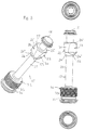
- Restriction cone 22 has a polygonal design with a circular-cylindrical shape, which preferably solely by slip fit, in exceptional cases having a slightly larger clearance, fits into seat 23, which like the restriction cone has a substantialextension length in the axial direction in such a way, that the latter always is guided by the seat irrespective of the restriction and cut-off position respectively.
- the polygonal design is preferably triangular in such a way, that three mainly flat surfaces 24 , having the same mutual angular distance along the circumference, intersect the cone starting from end surface 25, which is turned to value body 18 and at a somewhat smaller distance from spindle 21, e.g. 0.1-10 mm, preferably 1-4 mm in order to be located at the other end surface 26.
- the imaginary extensions of the surfaces intersect the spindle axis.
- the surfaces can be divided into two parts 24' and 24'', which enclose an angle of 150-179°, e.g. about 170°, said part 24'' running in parallel to the spindle.
- Restriction cone end 25, which is turned to value body 18, can be provided with a shorter or smaller bevel 27 on all sides and the other end 26 with a similar, preferably larger bevel 29.
- surfaces 24 and bevels 27,29 leave behind guide ridges 30, which are portions of said originally completely existing cylinder, which means, that said ridges, arranged with e.g. a 120° angular distance along the circumference, allow a continual centering of the restriction cone regardless of the axial position of control component and hence an exceedingly evenly distributed flow in the circumferential direction through this portion of the bypass past the constriction cone.
- a partition 31 is mounted in the housing between restriction cone 22 and value body 18 and is inserted in hole 9 in a radial direction with e.g. a few millimeters. It is designed to prevent, that the bypass flow and the return flow do not wrongly influence each other.
- the control component comprises at its rear/exterior end a screw plug 32 with an external thread 33, by means of which it is screwed into the exterior end of hole 9, which end within this area is partially provided with an interior thread 40. Also, the plug is sealed by means of an O-ring 35, inserted in a groove 34, a barrier ring 36, mounted outside the plug: in a groove 37, and finally a screw cap 38 with a flat seal 28. Plug 32 is in its exterior free end provided with e.g. a hexagonal hole 39 for a tool (not shown).
Landscapes
- Engineering & Computer Science (AREA)
- Thermal Sciences (AREA)
- Chemical & Material Sciences (AREA)
- Combustion & Propulsion (AREA)
- Mechanical Engineering (AREA)
- General Engineering & Computer Science (AREA)
- Physics & Mathematics (AREA)
- Pipe Accessories (AREA)
- Heat Treatment Of Articles (AREA)
- Steam Or Hot-Water Central Heating Systems (AREA)
- Rigid Pipes And Flexible Pipes (AREA)
- Prostheses (AREA)
- Sorption Type Refrigeration Machines (AREA)
- Other Air-Conditioning Systems (AREA)
- Physical Or Chemical Processes And Apparatus (AREA)
- Lift Valve (AREA)
- Pipeline Systems (AREA)
Abstract
Description
Claims (9)
- A distributor (7) for a single-tube system (1,2) of a heating or cooling plant having a feed tube (3) and a return and bypass tube (4) as wells as heating or cooling elements (5) and valves (6) provided for said tubes and elements, said distributor (7) comprising a housing (8) with an axial, continuous hole (9), one end of which forms or is connected to a return inlet (10), while through the other end a spindle-shaped control component (17) is inserted into said hole, a return outlet (11), a feed inlet (12) and a feed outlet (13) being laterally connected to hole (9), the insertion end of said component (17) comprising a valve body (18) provided to choke or shut off said return inlet (10) against a seat (19) in said housing (8), which seat is located between the return inlet (10) and the return outlet (11), the spindle (21) of said control component (17) being provided with a restriction cone (22) between said return outlet (11) and said feed inlet (12), a flow passage (20) connecting said feed outlet (13) with said feed inlet (12) via said hole (9), said cone (22) acting against a surrounding seat (23), which preferably is part of said housing (8) and which preferably is designed as a circular-cylindrical restriction, which jointly with the feed inlet (12), the return outlet (11) and portions of the hole (9), which interconnect said feed inlet (12) and said return outlet (11), constitutes the bypass of the system, characterized in that the restriction cone (22) has a polygonal shape, preferably with a partly circular-cylindrical circumference, and fits itself solely through slip fit into said surrounding seat (23) which, like the restriction cone (22), has substantial length in axial direction in such a way, that the restriction cone itself always is guided by the seat irrespective of its choking or shut-off position.
- A distributor according to claim 1, characterized in that the polygonal shape of said restriction cone (22) is triangular in cross-section.
- A distributor according to claim 2, c h a r a c t e r i z e d in t h a t said polygonal shape includes three surfaces (24), which are located with the same angular distance along the circumference of the cone (22).
- A distributor according to claim 2 or 3, characterized in that the originally existing or imaginary circular-cylindrical circumference remains in the form of axial guide ridges (30), which are located along the circumference with the same angular distance.
- A distributor according to claim 3 or 4, characterized in that said surfaces (24) intersect the cone (22), starting from one cone end surface (25), which faces said valve body (18), at short distance from the spindle (21), i.e. 0,1-10 mm, preferably 1-4 mm, which surfaces terminate, at the other end surface (26) of the cone, at 0,1-8 mm, preferably 0,5-2 mm, from the spindle, and that at least some parts of said surfaces (24) intersect the spindle axis with imaginary extensions.
- A distributor according to any of claims 3-5, characterized in that each surface (24) is composed of two partial surfaces (24', 24"), which include an angle of 150-179°, preferably about 170°, between each other, the one partial surface (24") preferably running in parallel with the spindle (21).
- A distributor according to any of claims 3-6, characterized in that the restriction cone end (25), which faces said valve body, is provided with a shorter or smaller bevel (27), and that the other cone end (26) is provided with a suitably longer or larger bevel (29).
- A distributor according to any of claims 1-7, characterized in that the housing (8), between the restriction cone (22) and the valve body (18), a partition (31) is formed, which radially projects into said hole (9) e.g. a few millimeters and is provided to separate, in this area, the bypass flow and the return flow.
- A distributor according to any of claims 1-8, characterized in that the control component (17) at its rear/exterior end has a screw plug (32) with an exterior thread (33), by means of which it is screwed into said other end of said hole (9), which end partially is provided with an interior thread (40), that in a groove (34) in said plug an O-ring (35) is inserted as a seal and suitably a carrier ring (36) is mounted outside the plug in a groove (37) in the housing and that a screw cap (38) with a flat seal (28) locks the control component which, in the exterior end surface of the plug, suitable is provided with e.g. a hexagonal hole (39) for the insertion of a tool for the positional adjustment of the control component.
Applications Claiming Priority (3)
| Application Number | Priority Date | Filing Date | Title |
|---|---|---|---|
| SE9502388 | 1995-06-30 | ||
| SE9502388A SE507600C2 (en) | 1995-06-30 | 1995-06-30 | Distributor included in a one-pipe system for a heating or cooling system |
| PCT/SE1996/000828 WO1997002457A1 (en) | 1995-06-30 | 1996-06-25 | Distributor comprised by a one-pipe-system for a heating or cooling apparatus |
Publications (2)
| Publication Number | Publication Date |
|---|---|
| EP0839304A1 EP0839304A1 (en) | 1998-05-06 |
| EP0839304B1 true EP0839304B1 (en) | 2001-08-29 |
Family
ID=20398810
Family Applications (1)
| Application Number | Title | Priority Date | Filing Date |
|---|---|---|---|
| EP96922329A Expired - Lifetime EP0839304B1 (en) | 1995-06-30 | 1996-06-25 | Distributor for a heating or cooling installation |
Country Status (9)
| Country | Link |
|---|---|
| EP (1) | EP0839304B1 (en) |
| AT (1) | ATE204979T1 (en) |
| AU (1) | AU6323496A (en) |
| DE (1) | DE69614859T2 (en) |
| DK (1) | DK0839304T3 (en) |
| NO (1) | NO310255B1 (en) |
| PL (1) | PL324024A1 (en) |
| SE (1) | SE507600C2 (en) |
| WO (1) | WO1997002457A1 (en) |
Families Citing this family (3)
| Publication number | Priority date | Publication date | Assignee | Title |
|---|---|---|---|---|
| AU2006200845C1 (en) * | 2006-02-28 | 2020-05-21 | Zetco Valves Pty Ltd | Plumbing Arrangements & Fittings |
| EP2522889B1 (en) * | 2011-05-09 | 2015-09-16 | Rettig ICC B.V. | Hot water supply control device |
| DE102011115101B4 (en) * | 2011-10-07 | 2014-10-30 | Gemeinnützige Wohnungsbaugesellschaft der Stadt Kassel mbH | Method and system for controlling single-pipe heating systems |
Family Cites Families (4)
| Publication number | Priority date | Publication date | Assignee | Title |
|---|---|---|---|---|
| SE177097C1 (en) * | 1961-01-01 | |||
| SE325454C (en) * | 1968-10-22 | 1976-02-23 | Markaryds Metallarmatur Ab | RADIATOR VALVE |
| GB1426799A (en) * | 1972-09-07 | 1976-03-03 | Fellingsbro Verkstaeder | Valves |
| SE418107B (en) * | 1972-11-06 | 1981-05-04 | Markaryds Metallarmatur Ab | DEVICE FOR CONNECTING A CONDUCTOR RADIATOR TO A CONDUCTOR CONTROL SYSTEM |
-
1995
- 1995-06-30 SE SE9502388A patent/SE507600C2/en not_active IP Right Cessation
-
1996
- 1996-06-25 PL PL96324024A patent/PL324024A1/en unknown
- 1996-06-25 DK DK96922329T patent/DK0839304T3/en active
- 1996-06-25 EP EP96922329A patent/EP0839304B1/en not_active Expired - Lifetime
- 1996-06-25 AU AU63234/96A patent/AU6323496A/en not_active Abandoned
- 1996-06-25 DE DE69614859T patent/DE69614859T2/en not_active Expired - Fee Related
- 1996-06-25 AT AT96922329T patent/ATE204979T1/en not_active IP Right Cessation
- 1996-06-25 WO PCT/SE1996/000828 patent/WO1997002457A1/en not_active Ceased
-
1997
- 1997-12-16 NO NO19975898A patent/NO310255B1/en unknown
Also Published As
| Publication number | Publication date |
|---|---|
| DK0839304T3 (en) | 2001-12-17 |
| DE69614859T2 (en) | 2002-05-02 |
| DE69614859D1 (en) | 2001-10-04 |
| SE9502388L (en) | 1996-12-31 |
| EP0839304A1 (en) | 1998-05-06 |
| PL324024A1 (en) | 1998-05-11 |
| AU6323496A (en) | 1997-02-05 |
| NO975898L (en) | 1997-12-16 |
| WO1997002457A1 (en) | 1997-01-23 |
| ATE204979T1 (en) | 2001-09-15 |
| SE9502388D0 (en) | 1995-06-30 |
| NO975898D0 (en) | 1997-12-16 |
| SE507600C2 (en) | 1998-06-22 |
| NO310255B1 (en) | 2001-06-11 |
Similar Documents
| Publication | Publication Date | Title |
|---|---|---|
| EP0783643B1 (en) | Valve for a system having a heat carrying medium | |
| US4807847A (en) | Valved oil pan plug | |
| US5178324A (en) | Method of regulating a central or district heating plant by means of a differential pressure valve, and unit for working method | |
| US5566711A (en) | Combined control and regulating valve for liquids or gases | |
| CA1260358A (en) | Radiator valve | |
| US4538637A (en) | Freeze proof faucet | |
| WO1995020733A1 (en) | Radiator valve | |
| US5290486A (en) | Desuperheater for controllable injection of cooling water in a steam or gas line | |
| WO1997002457A1 (en) | Distributor comprised by a one-pipe-system for a heating or cooling apparatus | |
| HK1003118B (en) | Apparatus for measurement and control, respectively, of temperature and/or pressure | |
| WO1991010852A1 (en) | Apparatus for measurement and control, respectively, of temperature and/or pressure | |
| CA1044562A (en) | Device for adapting the rate of flow of an automatic drinking bowl | |
| EP0783642B9 (en) | Valve for a system having a heat-carrying medium | |
| CA2080804A1 (en) | Diesel fuel heater | |
| US5931375A (en) | Valve for a system having an energy-carrying medium | |
| RU2208191C2 (en) | Valve | |
| US6102075A (en) | Flow control device | |
| RU2225576C2 (en) | Attachment fitting for heating member | |
| NL8103102A (en) | CLUTCH UNIT AND VALVE COMPOSITION FOR A FLUID FLOW PIPE. | |
| JPH0694907B2 (en) | Pipe fittings for radiator | |
| US4535934A (en) | Hot water heat distributor | |
| GB2363184A (en) | Valved radiator tail | |
| GB2232206A (en) | Air blower | |
| SU1218228A1 (en) | Regulating device | |
| JPS6030874A (en) | Sluice valve |
Legal Events
| Date | Code | Title | Description |
|---|---|---|---|
| PUAI | Public reference made under article 153(3) epc to a published international application that has entered the european phase |
Free format text: ORIGINAL CODE: 0009012 |
|
| 17P | Request for examination filed |
Effective date: 19971215 |
|
| AK | Designated contracting states |
Kind code of ref document: A1 Designated state(s): AT BE CH DE DK ES FI FR GB LI LU NL |
|
| 17Q | First examination report despatched |
Effective date: 19991021 |
|
| GRAG | Despatch of communication of intention to grant |
Free format text: ORIGINAL CODE: EPIDOS AGRA |
|
| RTI1 | Title (correction) |
Free format text: DISTRIBUTOR FOR A HEATING OR COOLING INSTALLATION |
|
| GRAG | Despatch of communication of intention to grant |
Free format text: ORIGINAL CODE: EPIDOS AGRA |
|
| GRAH | Despatch of communication of intention to grant a patent |
Free format text: ORIGINAL CODE: EPIDOS IGRA |
|
| GRAH | Despatch of communication of intention to grant a patent |
Free format text: ORIGINAL CODE: EPIDOS IGRA |
|
| GRAA | (expected) grant |
Free format text: ORIGINAL CODE: 0009210 |
|
| AK | Designated contracting states |
Kind code of ref document: B1 Designated state(s): AT BE CH DE DK ES FI FR GB LI LU NL |
|
| PG25 | Lapsed in a contracting state [announced via postgrant information from national office to epo] |
Ref country code: LI Free format text: LAPSE BECAUSE OF FAILURE TO SUBMIT A TRANSLATION OF THE DESCRIPTION OR TO PAY THE FEE WITHIN THE PRESCRIBED TIME-LIMIT Effective date: 20010829 Ref country code: CH Free format text: LAPSE BECAUSE OF FAILURE TO SUBMIT A TRANSLATION OF THE DESCRIPTION OR TO PAY THE FEE WITHIN THE PRESCRIBED TIME-LIMIT Effective date: 20010829 Ref country code: BE Free format text: LAPSE BECAUSE OF FAILURE TO SUBMIT A TRANSLATION OF THE DESCRIPTION OR TO PAY THE FEE WITHIN THE PRESCRIBED TIME-LIMIT Effective date: 20010829 |
|
| REF | Corresponds to: |
Ref document number: 204979 Country of ref document: AT Date of ref document: 20010915 Kind code of ref document: T |
|
| REG | Reference to a national code |
Ref country code: CH Ref legal event code: EP |
|
| REF | Corresponds to: |
Ref document number: 69614859 Country of ref document: DE Date of ref document: 20011004 |
|
| ET | Fr: translation filed | ||
| REG | Reference to a national code |
Ref country code: GB Ref legal event code: IF02 |
|
| PG25 | Lapsed in a contracting state [announced via postgrant information from national office to epo] |
Ref country code: ES Free format text: LAPSE BECAUSE OF FAILURE TO SUBMIT A TRANSLATION OF THE DESCRIPTION OR TO PAY THE FEE WITHIN THE PRESCRIBED TIME-LIMIT Effective date: 20020228 |
|
| REG | Reference to a national code |
Ref country code: CH Ref legal event code: PL |
|
| PGFP | Annual fee paid to national office [announced via postgrant information from national office to epo] |
Ref country code: FI Payment date: 20020315 Year of fee payment: 7 |
|
| PGFP | Annual fee paid to national office [announced via postgrant information from national office to epo] |
Ref country code: DE Payment date: 20020605 Year of fee payment: 7 |
|
| PGFP | Annual fee paid to national office [announced via postgrant information from national office to epo] |
Ref country code: DK Payment date: 20020620 Year of fee payment: 7 |
|
| PG25 | Lapsed in a contracting state [announced via postgrant information from national office to epo] |
Ref country code: LU Free format text: LAPSE BECAUSE OF NON-PAYMENT OF DUE FEES Effective date: 20020625 Ref country code: GB Free format text: LAPSE BECAUSE OF NON-PAYMENT OF DUE FEES Effective date: 20020625 |
|
| PGFP | Annual fee paid to national office [announced via postgrant information from national office to epo] |
Ref country code: NL Payment date: 20020628 Year of fee payment: 7 |
|
| PLBE | No opposition filed within time limit |
Free format text: ORIGINAL CODE: 0009261 |
|
| STAA | Information on the status of an ep patent application or granted ep patent |
Free format text: STATUS: NO OPPOSITION FILED WITHIN TIME LIMIT |
|
| 26N | No opposition filed | ||
| GBPC | Gb: european patent ceased through non-payment of renewal fee |
Effective date: 20020625 |
|
| PG25 | Lapsed in a contracting state [announced via postgrant information from national office to epo] |
Ref country code: FI Free format text: LAPSE BECAUSE OF NON-PAYMENT OF DUE FEES Effective date: 20030625 |
|
| PG25 | Lapsed in a contracting state [announced via postgrant information from national office to epo] |
Ref country code: DK Free format text: LAPSE BECAUSE OF NON-PAYMENT OF DUE FEES Effective date: 20030630 |
|
| PG25 | Lapsed in a contracting state [announced via postgrant information from national office to epo] |
Ref country code: NL Free format text: LAPSE BECAUSE OF NON-PAYMENT OF DUE FEES Effective date: 20040101 Ref country code: DE Free format text: LAPSE BECAUSE OF NON-PAYMENT OF DUE FEES Effective date: 20040101 |
|
| REG | Reference to a national code |
Ref country code: DK Ref legal event code: EBP |
|
| NLV4 | Nl: lapsed or anulled due to non-payment of the annual fee |
Effective date: 20040101 |
|
| PGFP | Annual fee paid to national office [announced via postgrant information from national office to epo] |
Ref country code: FR Payment date: 20050329 Year of fee payment: 10 |
|
| PGFP | Annual fee paid to national office [announced via postgrant information from national office to epo] |
Ref country code: AT Payment date: 20050405 Year of fee payment: 10 |
|
| PG25 | Lapsed in a contracting state [announced via postgrant information from national office to epo] |
Ref country code: AT Free format text: LAPSE BECAUSE OF NON-PAYMENT OF DUE FEES Effective date: 20060625 |
|
| REG | Reference to a national code |
Ref country code: FR Ref legal event code: ST Effective date: 20070228 |
|
| PG25 | Lapsed in a contracting state [announced via postgrant information from national office to epo] |
Ref country code: FR Free format text: LAPSE BECAUSE OF NON-PAYMENT OF DUE FEES Effective date: 20060630 |