EP0839263B1 - Kompressionsverringerungsmotorbremsen mit elektronisch gesteuerten multispulen hydraulikventilen - Google Patents
Kompressionsverringerungsmotorbremsen mit elektronisch gesteuerten multispulen hydraulikventilen Download PDFInfo
- Publication number
- EP0839263B1 EP0839263B1 EP95937473A EP95937473A EP0839263B1 EP 0839263 B1 EP0839263 B1 EP 0839263B1 EP 95937473 A EP95937473 A EP 95937473A EP 95937473 A EP95937473 A EP 95937473A EP 0839263 B1 EP0839263 B1 EP 0839263B1
- Authority
- EP
- European Patent Office
- Prior art keywords
- movable structure
- valve
- apparatus defined
- hydraulic fluid
- electrical
- Prior art date
- Legal status (The legal status is an assumption and is not a legal conclusion. Google has not performed a legal analysis and makes no representation as to the accuracy of the status listed.)
- Expired - Lifetime
Links
- 230000006835 compression Effects 0.000 title claims description 33
- 238000007906 compression Methods 0.000 title claims description 33
- 239000012530 fluid Substances 0.000 claims description 38
- 238000002485 combustion reaction Methods 0.000 claims description 4
- 230000000295 complement effect Effects 0.000 claims description 3
- 238000012544 monitoring process Methods 0.000 claims description 2
- 238000001514 detection method Methods 0.000 claims 2
- 239000003570 air Substances 0.000 description 7
- 238000010586 diagram Methods 0.000 description 3
- 239000000446 fuel Substances 0.000 description 3
- 230000005389 magnetism Effects 0.000 description 3
- 230000007246 mechanism Effects 0.000 description 3
- 239000012080 ambient air Substances 0.000 description 2
- 230000003111 delayed effect Effects 0.000 description 2
- 230000008030 elimination Effects 0.000 description 2
- 238000003379 elimination reaction Methods 0.000 description 2
- 230000005294 ferromagnetic effect Effects 0.000 description 2
- 230000001360 synchronised effect Effects 0.000 description 2
- 244000304337 Cuminum cyminum Species 0.000 description 1
- 230000005540 biological transmission Effects 0.000 description 1
- 238000006243 chemical reaction Methods 0.000 description 1
- 239000003302 ferromagnetic material Substances 0.000 description 1
- 239000010687 lubricating oil Substances 0.000 description 1
- 238000000034 method Methods 0.000 description 1
- 238000012986 modification Methods 0.000 description 1
- 230000004048 modification Effects 0.000 description 1
Images




Classifications
-
- F—MECHANICAL ENGINEERING; LIGHTING; HEATING; WEAPONS; BLASTING
- F01—MACHINES OR ENGINES IN GENERAL; ENGINE PLANTS IN GENERAL; STEAM ENGINES
- F01L—CYCLICALLY OPERATING VALVES FOR MACHINES OR ENGINES
- F01L13/00—Modifications of valve-gear to facilitate reversing, braking, starting, changing compression ratio, or other specific operations
- F01L13/06—Modifications of valve-gear to facilitate reversing, braking, starting, changing compression ratio, or other specific operations for braking
-
- F—MECHANICAL ENGINEERING; LIGHTING; HEATING; WEAPONS; BLASTING
- F02—COMBUSTION ENGINES; HOT-GAS OR COMBUSTION-PRODUCT ENGINE PLANTS
- F02D—CONTROLLING COMBUSTION ENGINES
- F02D13/00—Controlling the engine output power by varying inlet or exhaust valve operating characteristics, e.g. timing
- F02D13/02—Controlling the engine output power by varying inlet or exhaust valve operating characteristics, e.g. timing during engine operation
- F02D13/04—Controlling the engine output power by varying inlet or exhaust valve operating characteristics, e.g. timing during engine operation using engine as brake
Definitions
- This invention relates to compression release engine brakes, and more particularly to compression release engine brakes of the general type shown in Pitzi U.S. patent 5,012,778.
- compression release engine brakes operate to temporarily convert an associated internal combustion engine from a power source to a power sinking air compressor when the fuel supply to the engine is turned off and the engine brake is turned on.
- the engine brake operates in this way by opening an exhaust valve (or other special valve) in at least one cylinder of the engine at times when there is compressed air in the cylinder and before the engine can recover the work of compressing that air.
- the engine brake may open an exhaust valve near the end of each compression stroke of the engine cylinder served by that exhaust valve. This releases compressed air from the cylinder and prevents the engine from recovering the work of compressing that air during the subsequent "power" stroke of the cylinder.
- the engine therefore absorbs and dissipates much more energy than it otherwise would, and it becomes much more effective in slowing down the vehicle in which it is installed.
- the engine exhaust valves are opened mechanically or hydraulically.
- a hydraulically operated slave piston opens each exhaust valve.
- a hydraulic master piston actuated by another part of the engine is hydraulically connected to each slave piston.
- Each forward stroke of the master piston therefore produces a forward stroke of the associated slave piston which opens the associated engine exhaust valve.
- the engine part which actuates the master piston is selected so that the associated exhaust valve openings will have the timing required to produce good compression release engine braking.
- the master pistons may be operated by fuel injector mechanisms or by intake or exhaust valve opening mechanisms of the same or other engine cylinders.
- the resulting application of high pressure hydraulic fluid to the actuator cylinder causes an actuator piston in that cylinder to perform a forward stroke. This opens an exhaust valve in the associated engine cylinder. After each compression release event has occurred, the hydraulic valve is "closed” by de-energizing its coil. This disconnects the actuator cylinder from the high pressure source and instead connects the actuator cylinder to a relatively low pressure hydraulic fluid sink. The piston in the hydraulic actuator is thereby enabled to perform a return stroke, which allows the engine exhaust valve to close. Because the Pitzi patent systems are electrically controlled, the system designer has greater flexibility in selecting and implementing the timing of the compression release events.
- Elimination of the return spring may help reduce the electrical current and/or voltage required to operate the hydraulic valve because, when the return spring is eliminated, the electrical coil does not have to overcome the return spring force. Elimination of the return spring may also facilitate operating the hydraulic valve more rapidly and precisely, again because the force and inertia of the return spring do not have to be overcome by the electrical coil.
- each movable valve element makes a hydraulic connection between a source of relatively high pressure hydraulic fluid and a hydraulic actuator cylinder.
- each movable valve element makes a hydraulic connection between the actuator cylinder and a hydraulic fluid sink which is at a relatively low pressure.
- the hydraulic valve does not require its electromagnet coils to overcome any spring forces in order to shift the movable valve element. This helps make it possible to keep the valve small and quick-acting with relatively little electrical power required.
- the movable valve element can be held in either of its two positions by applying a relatively small holding current to the appropriate coil, or residual magnetism may be sufficient to hold the movable valve element in either of its two positions with no holding current being required.
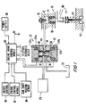
- FIG. 1 is a simplified, schematic block diagram of a representative portion of an illustrative compression release engine brake constructed in accordance with the principles of this invention. Portions of an internal combustion engine associated with the engine brake are also shown in FIG. 1.
- FIGS. 2a and 2b are simplified diagrams of illustrative electrical pulse trains that may be generated in a portion of the apparatus shown in FIG. 1 or other similar FIGS. or systems.
- FIGS. 2a and 2b are plotted against the same time reference to show how they may be synchronized with one another.
- FIGS. 2c and 2d are simplified diagrams of other illustrative electrical signals that may be generated in a portion of the apparatus shown in FIG. 1 or other similar FIGS. or systems.
- FIGS. 2c and 2d are plotted against the same time reference as FIGS. 2a and 2b, again to show how all of these signals are synchronized.
- FIG. 2e is a flow chart of illustrative operating sequence steps that can be performed in accordance with this invention as part of the operation of one of the components shown in FIG. 1 or other similar FIGS. or systems.
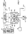
- FIG. 3 is a view similar to FIG. 1 showing an alternative type of hydraulic valve which can be used in accordance with the invention.
- FIG. 4 is another view similar to a portion of FIG. 1 or FIG. 3 showing another alternative type of hydraulic valve which can be used in accordance with the invention.
- FIG. 5 is a simplified, sectional view of still another type of hydraulic valve which can be used in accordance with the invention.
- FIG. 6 is a simplified, sectional view of yet another type of hydraulic valve which can be used in accordance with the invention.
- FIG. 7 is another view similar to FIG. 1 showing a more generic embodiment of the invention.
- high pressure hydraulic fluid source 20 may be similar to elements 10, 14, 16, and 18 in the above-mentioned Pitzi patent. Hydraulic fluid source 20 may therefore supply hydraulic fluid at a pressure of about 3000 psi. This high pressure hydraulic fluid is supplied to the inlet port 32 of spool valve 30. As in the Pitzi patent, the hydraulic fluid may be engine lubricating oil.
- Spool valve 30 has a substantially cylindrical movable valve element or spool 40 disposed in a complementary, substantially cylindrical bore in housing 50.
- Spool 40 is reciprocable relative to housing 50 parallel to the common central longitudinal axis 42 of the spool and bore. Except for passageway 44, the outer side surfaces of spool 40 complement the adjacent inner side surfaces of the bore in housing 50. There is a lap fit between the adjacent side surfaces of elements 40 and 50 so that spool 40 is slidable relative to housing 50 parallel to axis 42, but so that there is little or no hydraulic fluid leakage between elements 40 and 50.
- Spool 40 is preferably made of a ferromagnetic material or at least has ferromagnetic axial end portions.
- housing 50 At each end of housing 50 is a ferromagnetic pole piece 52a, 52b. A coil of wire 54a or 54b is disposed around a portion of each pole piece.
- spool 40 When engine brake control module 60 applies an electrical current to coil 54a, spool 40 is electromagnetically attracted to pole piece 52a as shown in FIG. 1. In this position inlet port 32 is hydraulically connected to outlet port 34 via passageway 44 in spool 40.
- spool 40 is electromagnetically attracted to pole piece 52b and therefore moves down from the position shown in FIG. 1. In this position valve 30 hydraulically connects output port 34 to drain port 36 via passageway 44 in spool 40.
- valve 30 breaks the hydraulic connection between ports 32 and 34 before making the hydraulic connection between ports 34 and 36.
- spool 40 moves in the opposite direction (i.e., the hydraulic connection between ports 34 and 36 is preferably broken before the hydraulic connection between ports 32 and 34 is made).
- the outlet port 34 of spool valve 30 is connected to the cylinder 72 of a hydraulic actuator 70 in the engine brake.
- the drain port 36 of the spool valve is connected to a hydraulic fluid sink 22 having a relatively low pressure.
- Hydraulic actuator cylinder 72 contains a reciprocable actuator piston 74. Piston 74 is resiliently urged upward toward return stop 76 by prestressed compression coil spring 78. However, when spool valve 30 supplies high pressure hydraulic fluid to cylinder 72, that fluid drives piston 74 down until it contacts a portion of engine exhaust valve opening mechanism 80, thereby opening exhaust valve 82 as shown in FIG. 1 and producing a compression release event in the internal combustion engine associated with the engine brake.
- engine brake control module 60 switches spool valve 30 to the condition in which port 34 is connected to port 36. This allows exhaust valve return spring 84 to close exhaust valve 82 and, in combination with actuator piston return spring 78, to cause actuator piston 74 to perform a return stroke. During such a return stroke, hydraulic fluid flows out of actuator cylinder 72 to sink 22 via valve 30.
- a relatively simple actuator structure 70 is shown in FIG. 1, any of the more sophisticated actuator structures shown in the Pitzi patent can be used instead if desired.
- Engine brake control module 60 is preferably a conventional microprocessor and memory or a similar device. Module 60 typically receives several signals to enable it to determine when to energize each coil of valve 30. For example, these input signals to module 60 may include a driver control signal 90 (e.g., from a switch on the vehicle's dashboard) whereby the driver indicates whether or not engine braking is desired. Conventional engine control module 92 typically provides another signal or signals indicative that the engine is in a condition suitable for operation of the engine brake. For example, this signal may only be produced when the fuel supply to the engine has been cut off, when the transmission is an appropriate gear, and when the clutch is engaged.
- driver control signal 90 e.g., from a switch on the vehicle's dashboard
- Conventional engine control module 92 typically provides another signal or signals indicative that the engine is in a condition suitable for operation of the engine brake. For example, this signal may only be produced when the fuel supply to the engine has been cut off, when the transmission is an appropriate gear, and when the clutch is engaged.
- engine brake control module 60 is programmed to automatically adjust the timing of compression release events based on such engine operating parameters as engine speed, cylinder pressure, turbocharger boost pressure, ambient air temperature, and/or ambient barometric pressure
- engine control module 92 may also provide one or more signals indicative of those engine operating parameters.
- Still another input to control module 60 is the output of conventional engine cam shaft position sensor 94. This signal provides the basic information required to enable module 60 to synchronize the timing of compression release events with the positions of the pistons in the engine cylinders.
- Module 60 also typically receives power from power supply 96 and ground potential via ground connection 98.
- Control module 60 can be programmed to process the input parameter values it receives in accordance with a predetermined algorithm to compute the exhaust valve opening timings that are most appropriate for those input parameter values. Alternatively, control module 60 can use its input parameter values to look up the appropriate corresponding exhaust valve opening timings in a look-up table stored in a memory of module 60. Control module 60 can thereby automatically adjust the exhaust valve opening timings to suit different engine operating conditions.
- exhaust valve opening timings can be somewhat delayed at relatively low engine speeds to maximize the available engine braking horsepower, while at higher engine speeds the exhaust valve openings can be somewhat advanced in time to prevent excessive forces on the engine brake or the engine components acted on by the engine brake.
- Exhaust valve opening timings can be somewhat delayed at high ambient air temperature or at low ambient barometric pressure to compensate for the reduced mass of air typically received by the engine under those conditions.
- the driver of the vehicle can set a desired engine or vehicle speed during engine braking, and control module 60 can advance or retard exhaust valve openings in the manner required to maintain that engine or vehicle speed.
- control module 60 can automatically adjust the amount of engine braking produced by not operating one or more of valves 30 when less engine braking is desired.
- Spool valve 30 requires relatively little electrical power to switch it, in part because there are no return spring forces to overcome. This fact also makes it possible to hold spool 40 in either of its two positions with a relatively low holding current.
- the signals applied to coils 54a and 54b may be as shown in FIGS. 2a and 2b, respectively.
- Each pulse applied to coil 54a includes an initial relatively high voltage portion 110 for causing spool 40 to move toward pole piece 52a. Thereafter a much lower voltage pulse portion 112 is applied to coil 54a to hold spool 40 against pole piece 52a.
- each pulse applied to coil 54b includes an initial relatively high voltage portion 120 for causing spool 40 to move toward pole piece 52b, followed by a lower voltage holding pulse portion 122 for holding spool 40 against pole piece 52b.
- valves 30 Another refinement that is possible with valves 30 is to use each coil 54 to detect when spool 40 has shifted away from that coil. Such movement of spool 40 tends to induce a small electrical current in the adjacent coil. This is illustrated by FIGS. 2c and 2d which show electrical currents induced in coils 54a and 54b, respectively. For example, during each pulse portion 110 in FIG. 2a, spool 40 shifts away from coil 54b toward coil 54a. This movement of spool 40 induces a small electrical current pulse 125b in coil 54b. Control module 60 can detect each such pulse 125b and can use that information for such purposes as to confirm that spool 40 has shifted as intended and/or to determine when to terminate the pulse portion 110 producing that spool movement.
- Control module 60 can detect the resulting electrical current pulse 125a induced in coil 54a in order to confirm the intended movement of spool 40 and/or to determine when to terminate the pulse portion 120 causing that spool movement.
- FIG. 2e shows an illustrative operating sequence for control module 60 to make use of signals of the type shown in FIGS. 2c and 2d to determine when control module 60 should terminate the portion 110 or 120 of each pulse shown in FIGS. 2a and 2b.
- processor 60 begins to apply the portion 110 or 120 of a pulse to the associated coil in valve 30.
- processor 60 monitors the other coil of valve 30 until an induced current pulse 125 is detected in that other coil, thereby indicating that spool 40 has shifted. Control then passes from step 102 to step 104.
- step 104 processor 60 terminates the pulse portion 110 or 120 initiated in step 100.
- processor initiates the portion 112 or 122 of the pulse referred to in steps 100 and 104.
- step 106 can be omitted if residual magnetism is sufficient to hold spool 40 in place after it has been shifted by pulse portions 110 or 120.
- FIG. 3 shows an alternative embodiment in which a two-coil poppet-type valve 130 is used in place of each spool-type valve 30 in the embodiment shown in FIG. 1. Except for the use of a different type of hydraulic valve, the apparatus of FIG. 3 may be constructed and may operate similarly to the apparatus of FIG. 1. Parts in FIG. 3 that are substantially the same as parts in FIG. 1 have the same reference numbers in both FIGS. and will not be described again in connection with FIG. 3. Parts in FIG. 3 that are generally similar to parts in FIG. 1 have reference numbers that are increased by 100 as compared to FIG. 1.
- movable valve element or plunger 140 is disposed in housing 150 for movement left or right relative to the housing.
- Plunger 140 is electromagnetically attracted to the right when engine brake control module 60 energizes coil 154a and thereby magnetizes pole piece 152a.
- Plunger 140 shifts to the left when control module 60 energizes coil 154b and thereby magnetizes pole piece 152b.
- the shoulder 146a on the enlarged portion of the plunger seats against the shoulder 148a on the inside of housing 150. This prevents hydraulic fluid from flowing from either high pressure hydraulic fluid source 20 or from actuator 70 to low pressure hydraulic fluid sump 22.
- plunger 140 in this position, high pressure hydraulic fluid can flow from source 20, through valve inlet port 132 and valve port 134 to actuator 70 to drive the piston in the actuator down and thereby produce a compression release event in the associated engine.
- engine brake control module 60 When a compression release event has been produced and it is desired to allow actuator 70 to perform a return stroke, engine brake control module 60 energizes coil 154b instead of coil 154a. This shift plunger 140 to the left, thereby causing plunger shoulder 146b to seat against housing seat 148b. With plunger 140 in this position high pressure hydraulic fluid supply 20 is cut off from actuator 70. Instead, hydraulic fluid can flow from actuator 70 through valve ports 134 and 136 to sump 22, thereby allowing actuator 70 to perform a return stroke.
- valve 130 is constructed somewhat differently than valve 30, many of the operating principles discussed above in connection with valve 30 are equally applicable to valve 130.
- the types of coil-energizing signals shown in FIGS. 2a and 2b can be used to operate valve 130, and the valve-monitoring signals shown in FIGS. 2c and 2d can also be detected in valve 130.
- FIG. 4 Another alternative embodiment is shown in FIG. 4.
- the moving element in hydraulic valve 230 is ball 240.
- Ball 240 can be pushed to the right in housing 250 by electrically energizing coil 254a in the valve. This magnetizes pole piece 252a which attracts the head of pin 256a to that armature. The end of pin 256a remote from pole piece 252a then pushes ball 240 against seat 248b in housing 250. This prevents hydraulic fluid from flowing from valve 230 to sump 22, but allows high pressure hydraulic fluid to flow from source 20 through valve 230 to actuator 70, thereby causing a forward stroke of the actuator and producing a compression release event in the associated engine.
- engine brake control module 60 energizes coil 254b rather than coil 254a. This attracts the head of pin 256b to pole piece 252b, thereby pushing ball 240 to the left against seat 248a in housing 250. With ball 240 against seat 248a the supply of high pressure hydraulic fluid from source 20 is cut off and actuator 70 can instead drain to sump 22 via valve 230.
- valve 230 is constructed somewhat differently than valve 130, all of the operating principles discussed above in connection with valve 130 are equally applicable to systems employing valves like valve 230.
- element 240 can have other shapes.
- element 240 can be a cylinder whose longitudinal axis is perpendicular to the plane of the paper on which FIG. 4 is drawn.
- FIG. 5 shows still another type of multiple-coil hydraulic valve 330 that can be used in the systems of this invention.
- ball or cylinder 340 is rotatable relative to housing 350 about a central axis which is perpendicular to the plane of the sheet on which FIG. 5 is drawn.
- Permanent magnets 341 are carried by ball or cylinder 340.
- coils 354a When coils 354a are energized, ball 340 rotates counter-clockwise to the position shown in FIG. 5, thereby connecting high pressure hydraulic fluid inlet 332 to hydraulic actuator connection 334 via the passageway 344 through ball or cylinder 340.
- coils 354b rather than coils 354a are energized, ball or cylinder 340 rotates clockwise approximately 36° from the position shown in FIG. 5. This disconnects conduit 332 from conduit 334, and instead connects conduit 334 to low pressure hydraulic fluid sump connection 336.
- FIG. 6 shows yet another type of multiple-coil hydraulic valve 430 that can be used in the systems of this invention.
- This valve may be similar to previously described valves such as valve 30 in FIG. 1 or valve 130 in FIG. 3, except that in valve 430 both of electromagnetic coils 454a and 454b are on the same side or end of movable valve element 440.
- coil 454a When coil 454a is energized, movable armature member 458 is electromagnetically attracted to and shifts toward fixed pole piece 452a. This shifts movable valve element 440 so that it closes off conduit 436 but makes a hydraulic connection between conduits 432 and 434.
- FIG. 7 shows a generic type of valve 530 in accordance with this invention.
- Valve 530 has an "on" coil 554a and an “off” coil 554b.
- When "on" coil 554a is energized by engine brake control module 60 valve 530 connects high pressure hydraulic fluid source 20 to actuator 70. This causes actuator 70 to perform a forward stroke, thereby producing a compression release event in the associated engine.
- control module 60 energizes "off" coil 554b. This disconnects actuator 70 from hydraulic fluid source 20 and connects the actuator instead to hydraulic fluid sump 22. Actuator 70 is then able to perform a return stroke.
- valve 82 is a conventional exhaust valve, those skilled in the art will appreciate that it can alternatively be a special-purpose valve added just for use during engine braking as shown, for example, in Gobert et al. U.S. patent 5,146,890.
- exhaust valve used herein and in the appended claims include both conventional exhaust valves and special-purpose valves added for use to produce compression release events.
- the apparatus of this invention can be used not only to produce compression release events near the end of the compression strokes of the engine cylinders, but alternatively or in addition to produce compression release events near the end of the exhaust strokes of the engine cylinders if the engine is capable of suppressing its normal exhaust-stroke exhaust valve openings during operation of the engine brake. See, for example, Sickler U.S. patent 4,572,114 which shows conversion of a four-cycle engine to a two-cycle air compressor during engine braking.
Landscapes
- Engineering & Computer Science (AREA)
- Mechanical Engineering (AREA)
- General Engineering & Computer Science (AREA)
- Chemical & Material Sciences (AREA)
- Combustion & Propulsion (AREA)
- Valve Device For Special Equipments (AREA)
- Output Control And Ontrol Of Special Type Engine (AREA)
Claims (15)
- Kompressionsverringernde Motorbremse zum Öffnen eines Auslaßventils (82) in einem Zylinder eines Verbrennungsmotors, das mit der Motorbremse zum Freigeben in dem Zylinder komprimierter Luft in Verbindung steht, mit:einer Quelle (20) für Hydraulikfluid unter relativ hohem Druck;einem Becken (22) für Hydraulikfluid unter relativ niedrigem Druck;einem in einem hydraulischen Stellkolbenzylinder (72) hin- und herbewegbaren hydraulischen Stellkolben (74), wobei das Auslaßventil (82) durch einen Vorwärtshub des Stellkolbens (74) in Abhängigkeit von dem in den Stellkolbenzylinder (72) eingeleiteten, unter relativ hohem Druck stehenden Hydraulikfluid geöffnet wird und dabei einen relativ hohen Hydraulikfluiddruck auf eine Seite des Stellkolbens (74) ausübt, um den Vorwärtshub hervorzurufen, und wobei der Stellkolben (74) in Abhängigkeit von einer auf das Auslaßventil (82) wirkenden Rückstellfederkraft (84) einen Rückwärtshub zum Schließen des Auslaßventils (82) ausübt, wenn der Stellkolbenzylinder (72) mit dem Becken (22) für Hydraulikfluid hydraulisch verbunden ist;ein Ventil (30) mit einem relativ zu einem Gehäuse (50) zwischen ersten und zweiten Positionen bewegbaren Element (40), wobei das bewegbare Element eine hydraulische Verbindung zwischen der Quelle (20) für hydraulisches Fluid und dem Stellkolbenzylinder (72) öffnet, wenn das bewegbare Element (40) in der ersten Position ist, und das bewegbare Element (40) eine hydraulische Verbindung zwischen dem Stellkolbenzylinder (72) und dem Becken (22) für hydraulisches Fluid öffnet, wenn das bewegbare Element (40) in der zweiten Position ist, wobei das Ventil (30) einen ersten Elektromagneten (52a, 54a) zum Bewegen des bewegbaren Elements (40) aus der zweiten Position zur ersten Position in Abhängigkeit von einer elektrischen Erregung des ersten Elektromagneten (52a, 54a) und einen zweiten Elektromagneten (52b, 54b) zum Bewegen des bewegbaren Elements aus der ersten Position zur zweiten Position in Abhängigkeit von einer elektrischen Erregung des zweiten Elektromagneten (52b, 54b) aufweist; undeine elektrische Steuerung (60) zum wahlweisen Erregen der ersten und zweiten Elektromagneten (52a, 54a, 52b, 54b), wobei das bewegbare Element (40) über die gesamte Strecke von der zweiten Position zur ersten Position ausschließlich durch den ersten Elektromagneten (52a, 54a) bewegt wird und wobei das bewegbare Element (40) über die gesamte Strecke von der ersten Position zur zweiten Position ausschließlich durch den zweiten Elektromagneten (52b, 54b) bewegt wird.
- Vorrichtung nach Anspruch 1, wobei der erste und der zweite Elektromagnet jeweils aufweisen:
erste und zweite elektrische Spulen zum jeweiligen Bewegen des bewegbaren Elements zur ersten oder zweiten Position, wenn elektrischer Strom durch die erste oder zweite elektrische Spule fließt. - Vorrichtung nach Anspruch 2, wobei die elektrische Steuerung ferner aufweist:
einen Regler zum Anlegen eines elektrischen Impulses an mindestens eine der Spulen, wobei der Impuls einen ersten elektrisch starken Abschnitt zum Bewegen des bewegbaren Elements zu einer zugehörigen Position und einen zweiten elektrisch schwachen Abschnitt zum Halten des bewegbaren Elements in der zugehörigen Position aufweist. - Vorrichtung nach Anspruch 2, wobei der erste und der zweite Elektromagnet jeweils ferner aufweisen:
einen jeweiligen ersten und zweiten Polschuh. - Vorrichtung nach Anspruch 4, wobei das bewegbare Element in mindestens einer der ersten und zweiten Positionen durch Restmagnetismus zwischen dem bewegbaren Element und dem Polschuh des einen der beiden Elektromagneten gehalten wird, der zu dem bewegbaren Element in der mindestens einen der ersten und zweiten Positionen benachbart ist.
- Vorrichtung nach Anspruch 2, wobei die elektrische Steuerung einen elektrischen Impuls an mindestens eine der Spulen anlegt, während an der anderen der Spulen ein elektrisches Signal abgegriffen wird, das in der anderen der Spulen durch die Bewegung des bewegbaren Elements relativ zu den Spulen induziert wird.
- Vorrichtung nach Anspruch 6, wobei die elektrische Steuerung auf das Feststellen des induzierten elektrischen Signals reagiert, indem die Stärke des an die mindestens eine Spule angelegten elektrischen Impulses zumindest wesentlich reduziert wird.
- Vorrichtung nach Anspruch 7, wobei die elektrische Steuerung auf das Feststellen des induzierten elektrischen Signals reagiert, indem der an die mindestens eine Spule angelegte elektrische Impuls beendet wird.
- Vorrichtung nach Anspruch 1, wobei das bewegbare Element einen Spindelkörper mit einer longitudinalen Achse aufweist und wobei sich der Spindelkörper zwischen der ersten und der zweiten Position parallel zu dieser Achse hin- und herbewegt.
- Vorrichtung nach Anspruch 9, wobei der Spindelkörper äußere Seitenflächen aufweist, die im wesentlichen parallel zu der Achse sind, und wobei das Gehäuse innere Seitenflächen aufweist, die im wesentlichen parallel zu der Achse, komplementär zu den äußeren Seitenflächen und in Gleitkontakt mit den äußeren Seitenflächen im wesentlichen parallel zu der Achse sind.
- Vorrichtung nach Anspruch 10, wobei das Gehäuseelement erste, zweite und dritte Öffnungen durch die inneren Seitenflächen aufweist, wobei die erste Öffnung hydraulisch mit der Quelle für Hydraulikfluid, die zweite Öffnung hydraulisch mit dem Becken für Hydraulikfluid und die dritte Öffnung hydraulisch mit dem Stellzylinder verbunden sind und der Spindelkörper einen Durchgang zum hydraulischen Verbinden der ersten und dritten Öffnungen aufweist, wenn der Spindelkörper in der ersten Position ist, und zum hydraulischen Verbinden der zweiten und dritten Öffnungen, wenn der Spindelkörper in der zweiten Position ist.
- Vorrichtung nach Anspruch 1, wobei das bewegbare Element ein zwischen ersten und zweiten Ventilsitzen auf- und abgehendes bewegbares Element aufweist, wobei das auf- und abgehende Element einen Durchgang durch den ersten Ventilsitz schließt, wenn das bewegbare Element in der ersten Position und das auf- und abgehende Element dementsprechend auf dem ersten Ventilsitz ist, und wobei das auf- und abgehende Element einen Durchgang durch den zweiten Ventilsitz verschließt, wenn das bewegbare Element in der zweiten Position und das auf- und abgehende Element demgemäß auf dem zweiten Ventilsitz ist.
- Vorrichtung nach Anspruch 12, wobei das auf- und abgehende Element eine Kugel ist.
- Vorrichtung nach Anspruch 12, wobei das auf- und abgehende Element ein Zylinder ist.
- Vorrichtung nach Anspruch 1, wobei das bewegbare Element ein elektromagnetisch drehbares Element aufweist.
Applications Claiming Priority (3)
| Application Number | Priority Date | Filing Date | Title |
|---|---|---|---|
| US08/319,734 US5479890A (en) | 1994-10-07 | 1994-10-07 | Compression release engine brakes with electronically controlled, multi-coil hydraulic valves |
| US319734 | 1994-10-07 | ||
| PCT/US1995/013279 WO1996011327A2 (en) | 1994-10-07 | 1995-10-04 | Compression release engine brakes with electronically controlled, multi-coil hydraulic valves |
Publications (2)
| Publication Number | Publication Date |
|---|---|
| EP0839263A2 EP0839263A2 (de) | 1998-05-06 |
| EP0839263B1 true EP0839263B1 (de) | 2000-03-15 |
Family
ID=23243443
Family Applications (1)
| Application Number | Title | Priority Date | Filing Date |
|---|---|---|---|
| EP95937473A Expired - Lifetime EP0839263B1 (de) | 1994-10-07 | 1995-10-04 | Kompressionsverringerungsmotorbremsen mit elektronisch gesteuerten multispulen hydraulikventilen |
Country Status (5)
| Country | Link |
|---|---|
| US (1) | US5479890A (de) |
| EP (1) | EP0839263B1 (de) |
| JP (1) | JPH10509491A (de) |
| DE (1) | DE69515705T2 (de) |
| WO (1) | WO1996011327A2 (de) |
Families Citing this family (58)
| Publication number | Priority date | Publication date | Assignee | Title |
|---|---|---|---|---|
| US5647318A (en) | 1994-07-29 | 1997-07-15 | Caterpillar Inc. | Engine compression braking apparatus and method |
| US5718199A (en) * | 1994-10-07 | 1998-02-17 | Diesel Engine Retarders, Inc. | Electronic controls for compression release engine brakes |
| US5619965A (en) | 1995-03-24 | 1997-04-15 | Diesel Engine Retarders, Inc. | Camless engines with compression release braking |
| US7222614B2 (en) * | 1996-07-17 | 2007-05-29 | Bryant Clyde C | Internal combustion engine and working cycle |
| US7281527B1 (en) * | 1996-07-17 | 2007-10-16 | Bryant Clyde C | Internal combustion engine and working cycle |
| US8215292B2 (en) * | 1996-07-17 | 2012-07-10 | Bryant Clyde C | Internal combustion engine and working cycle |
| US6951211B2 (en) | 1996-07-17 | 2005-10-04 | Bryant Clyde C | Cold air super-charged internal combustion engine, working cycle and method |
| JP4261767B2 (ja) * | 1997-10-03 | 2009-04-30 | ジェイコブス ビークル システムズ、インコーポレイテッド | 内燃機関における排気ガスパラメータを制御する方法と装置 |
| US8820276B2 (en) * | 1997-12-11 | 2014-09-02 | Jacobs Vehicle Systems, Inc. | Variable lost motion valve actuator and method |
| US6000374A (en) * | 1997-12-23 | 1999-12-14 | Diesel Engine Retarders, Inc. | Multi-cycle, engine braking with positive power valve actuation control system and process for using the same |
| US6380787B1 (en) * | 1999-08-31 | 2002-04-30 | Micron Technology, Inc. | Integrated circuit and method for minimizing clock skews |
| US6283090B1 (en) | 1999-11-17 | 2001-09-04 | Caterpillar Inc. | Method and apparatus for operating a hydraulically-powered compression release brake assembly on internal combustion engine |
| US6453873B1 (en) * | 2000-11-02 | 2002-09-24 | Caterpillar Inc | Electro-hydraulic compression release brake |
| US6568367B2 (en) * | 2001-07-31 | 2003-05-27 | Caterpillar Inc | Engine compression release brake system and method of operation |
| US6715466B2 (en) | 2001-12-17 | 2004-04-06 | Caterpillar Inc | Method and apparatus for operating an internal combustion engine exhaust valve for braking |
| US6601563B2 (en) | 2001-12-20 | 2003-08-05 | Caterpillar Inc | Exhaust gas re-circulation with a compression release brake actuator |
| US7178492B2 (en) | 2002-05-14 | 2007-02-20 | Caterpillar Inc | Air and fuel supply system for combustion engine |
| US7347171B2 (en) * | 2002-02-04 | 2008-03-25 | Caterpillar Inc. | Engine valve actuator providing Miller cycle benefits |
| US6732685B2 (en) | 2002-02-04 | 2004-05-11 | Caterpillar Inc | Engine valve actuator |
| US6722349B2 (en) | 2002-02-04 | 2004-04-20 | Caterpillar Inc | Efficient internal combustion engine valve actuator |
| US20050247286A1 (en) * | 2002-02-04 | 2005-11-10 | Weber James R | Combustion engine including fluidically-controlled engine valve actuator |
| US7201121B2 (en) * | 2002-02-04 | 2007-04-10 | Caterpillar Inc | Combustion engine including fluidically-driven engine valve actuator |
| US6688280B2 (en) * | 2002-05-14 | 2004-02-10 | Caterpillar Inc | Air and fuel supply system for combustion engine |
| US20050241597A1 (en) * | 2002-05-14 | 2005-11-03 | Weber James R | Air and fuel supply system for a combustion engine |
| US7069887B2 (en) | 2002-05-14 | 2006-07-04 | Caterpillar Inc. | Engine valve actuation system |
| US20050235950A1 (en) * | 2002-05-14 | 2005-10-27 | Weber James R | Air and fuel supply system for combustion engine |
| US7191743B2 (en) * | 2002-05-14 | 2007-03-20 | Caterpillar Inc | Air and fuel supply system for a combustion engine |
| US7252054B2 (en) * | 2002-05-14 | 2007-08-07 | Caterpillar Inc | Combustion engine including cam phase-shifting |
| US6941909B2 (en) * | 2003-06-10 | 2005-09-13 | Caterpillar Inc | System and method for actuating an engine valve |
| US20050235953A1 (en) * | 2002-05-14 | 2005-10-27 | Weber James R | Combustion engine including engine valve actuation system |
| US20050229900A1 (en) * | 2002-05-14 | 2005-10-20 | Caterpillar Inc. | Combustion engine including exhaust purification with on-board ammonia production |
| US20050247284A1 (en) * | 2002-05-14 | 2005-11-10 | Weber James R | Air and fuel supply system for combustion engine operating at optimum engine speed |
| US7004122B2 (en) * | 2002-05-14 | 2006-02-28 | Caterpillar Inc | Engine valve actuation system |
| US20050235951A1 (en) * | 2002-05-14 | 2005-10-27 | Weber James R | Air and fuel supply system for combustion engine operating in HCCI mode |
| US20040177837A1 (en) * | 2003-03-11 | 2004-09-16 | Bryant Clyde C. | Cold air super-charged internal combustion engine, working cycle & method |
| AU2003901193A0 (en) | 2003-03-17 | 2003-04-03 | Gram Engineering Pty Ltd | Building element with varying surface characteristics |
| US6912458B2 (en) * | 2003-06-25 | 2005-06-28 | Caterpillar Inc | Variable valve actuation control for operation at altitude |
| US20050039711A1 (en) * | 2003-08-18 | 2005-02-24 | Bryant Clyde C. | Internal combustion engine and working cycle |
| JP2006029247A (ja) * | 2004-07-20 | 2006-02-02 | Denso Corp | エンジンの停止始動制御装置 |
| US20060238285A1 (en) * | 2005-03-30 | 2006-10-26 | Dimig Steven J | Residual magnetic devices and methods |
| US20060219497A1 (en) * | 2005-03-30 | 2006-10-05 | Organek Gregory J | Residual magnetic devices and methods |
| US20060226941A1 (en) * | 2005-03-30 | 2006-10-12 | Dimig Steven J | Residual magnetic devices and methods |
| US20060238284A1 (en) * | 2005-03-30 | 2006-10-26 | Dimig Steven J | Residual magnetic devices and methods |
| US20060219499A1 (en) * | 2005-03-30 | 2006-10-05 | Organek Gregory J | Residual magnetic devices and methods |
| US20060219498A1 (en) * | 2005-03-30 | 2006-10-05 | Organek Gregory J | Residual magnetic devices and methods |
| US20060219513A1 (en) * | 2005-03-30 | 2006-10-05 | Organek Gregory J | Residual magnetic devices and methods |
| US8403124B2 (en) | 2005-03-30 | 2013-03-26 | Strattec Security Corporation | Residual magnetic devices and methods |
| US7969705B2 (en) * | 2005-03-30 | 2011-06-28 | Strattec Security Corporation | Residual magnetic devices and methods |
| US20060237959A1 (en) * | 2005-03-30 | 2006-10-26 | Dimig Steven J | Residual magnetic devices and methods |
| US20060226942A1 (en) * | 2005-03-30 | 2006-10-12 | Dimig Steven J | Residual magnetic devices and methods |
| US7401483B2 (en) * | 2005-03-30 | 2008-07-22 | Strattec Security Corporation | Residual magnetic devices and methods for an ignition actuation blockage device |
| US9784147B1 (en) | 2007-03-07 | 2017-10-10 | Thermal Power Recovery Llc | Fluid-electric actuated reciprocating piston engine valves |
| CN101978152B (zh) * | 2008-03-17 | 2013-07-03 | 胡斯华纳有限公司 | 燃料供应单元 |
| US8689769B2 (en) * | 2010-05-12 | 2014-04-08 | Caterpillar Inc. | Compression-braking system |
| US10072589B2 (en) * | 2015-12-22 | 2018-09-11 | Scania Cv Ab | Method for checking the function of a compression release brake system |
| SE1850106A1 (en) * | 2018-01-30 | 2019-07-31 | Scania Cv Ab | Compression Release Brake Arrangement, Method of Controlling a Compression Release Brake Arrangement, and Related Devices |
| SE541737C2 (en) * | 2018-01-30 | 2019-12-03 | Scania Cv Ab | Compression Release Brake Arrangement, Method of Controlling a Compression Release Brake Arrangement, and Related Devices |
| SE1950884A1 (en) * | 2019-07-11 | 2020-11-17 | Scania Cv Ab | Control device and method for controlling a compression release brake arrangement, computer program, computer-readable medium and vehicle |
Family Cites Families (13)
| Publication number | Priority date | Publication date | Assignee | Title |
|---|---|---|---|---|
| US3220392A (en) * | 1962-06-04 | 1965-11-30 | Clessie L Cummins | Vehicle engine braking and fuel control system |
| US3743898A (en) * | 1970-03-31 | 1973-07-03 | Oded Eddie Sturman | Latching actuators |
| US4572114A (en) * | 1984-06-01 | 1986-02-25 | The Jacobs Manufacturing Company | Process and apparatus for compression release engine retarding producing two compression release events per cylinder per engine cycle |
| US4664070A (en) * | 1985-12-18 | 1987-05-12 | The Jacobs Manufacturing Company | Hydro-mechanical overhead for internal combustion engine |
| USRE33052E (en) * | 1986-06-10 | 1989-09-12 | The Jacobs Manufacturing Company | Compression release retarder with valve motion modifier |
| US4898128A (en) * | 1988-04-07 | 1990-02-06 | Meneely Vincent A | Anti-lash adjuster |
| SE466320B (sv) * | 1989-02-15 | 1992-01-27 | Volvo Ab | Foerfarande och anordning foer motorbromsning med en fyrtakts foerbraenningsmotor |
| US4936273A (en) * | 1989-04-28 | 1990-06-26 | Myers Vaughn D | Decompression system for diesel engines |
| US4976227A (en) * | 1990-04-16 | 1990-12-11 | Draper David J | Internal combustion engine intake and exhaust valve control apparatus |
| US5012778A (en) * | 1990-09-21 | 1991-05-07 | Jacobs Brake Technology Corporation | Externally driven compression release retarder |
| US5253619A (en) * | 1992-12-09 | 1993-10-19 | North American Philips Corporation | Hydraulically powered actuator with pneumatic spring and hydraulic latching |
| US5335633A (en) * | 1993-06-10 | 1994-08-09 | Thien James L | Internal combustion engine valve actuator apparatus |
| US5357926A (en) * | 1993-08-26 | 1994-10-25 | Jacobs Brake Technology Corporation | Compression release engine brake with selectively reduced engine exhaust noise |
-
1994
- 1994-10-07 US US08/319,734 patent/US5479890A/en not_active Expired - Lifetime
-
1995
- 1995-10-04 EP EP95937473A patent/EP0839263B1/de not_active Expired - Lifetime
- 1995-10-04 JP JP8512728A patent/JPH10509491A/ja active Pending
- 1995-10-04 DE DE69515705T patent/DE69515705T2/de not_active Expired - Fee Related
- 1995-10-04 WO PCT/US1995/013279 patent/WO1996011327A2/en not_active Ceased
Also Published As
| Publication number | Publication date |
|---|---|
| JPH10509491A (ja) | 1998-09-14 |
| EP0839263A2 (de) | 1998-05-06 |
| WO1996011327A2 (en) | 1996-04-18 |
| WO1996011327A3 (en) | 1996-09-19 |
| DE69515705T2 (de) | 2000-11-09 |
| MX9702514A (es) | 1998-10-31 |
| US5479890A (en) | 1996-01-02 |
| DE69515705D1 (de) | 2000-04-20 |
Similar Documents
| Publication | Publication Date | Title |
|---|---|---|
| US5479890A (en) | Compression release engine brakes with electronically controlled, multi-coil hydraulic valves | |
| EP0367448B1 (de) | Ventilsteuerungsvorrichtung für Brennkraftmaschinen | |
| US5526784A (en) | Simultaneous exhaust valve opening braking system | |
| EP0912819B1 (de) | Hydraulisch betätigte ansaug/auslass hubventil | |
| US4777915A (en) | Variable lift electromagnetic valve actuator system | |
| US7596445B2 (en) | Method for improving the operation of electrically controlled actuators for an internal combustion engine | |
| EP0397359A2 (de) | Brennkraftmaschine mit variablem Zyklus | |
| US20110120411A1 (en) | Solenoid control for valve actuation in engine brake | |
| US6964270B2 (en) | Dual mode EGR valve | |
| US5537975A (en) | Electronically controlled compression release engine brakes | |
| US7066141B2 (en) | Linear control valve for controlling a fuel injector and engine compression release brake actuator and engine using same | |
| JP2000130198A (ja) | 電磁駆動弁の制御装置 | |
| US4870930A (en) | Engine valve control apparatus | |
| EP1403471A3 (de) | Variable Ventilsteuerungseinrichtung für eine Brennkraftmaschine | |
| US7007643B2 (en) | Engine valve actuation system | |
| EP1199458A3 (de) | Kraftstoffeinspritzeinrichtung für eine Brennkraftmaschine und Steuerungsverfahren dafür | |
| WO2004064083A3 (en) | Electromagnetic actuator for a fuel injector having an integral magnetic core and injector valve body | |
| EP1106791A3 (de) | Elektronisches Steuersystem für ein elektromagnetisches Stellmittel | |
| US6729278B2 (en) | Dual coil, dual lift electromechanical valve actuator | |
| MXPA97002514A (es) | Frenos de motor para alivio de la compresion con valvulas hidraulicas de varias bobinas controladas electronicamente | |
| EP1331369B1 (de) | Linearantriebsvorrichtung und Antriebskontrollverfahren | |
| EP1275827A2 (de) | Dekompressionsmotorbremse und Motor, welcher diese nutzt | |
| MXPA97002513A (en) | Controlled motor compression release brakes electronicame | |
| JP2002054409A (ja) | 内燃機関における電磁駆動弁の開閉制御方法 | |
| JPS61226510A (ja) | 内燃機関のバルブロツク装置 |
Legal Events
| Date | Code | Title | Description |
|---|---|---|---|
| PUAI | Public reference made under article 153(3) epc to a published international application that has entered the european phase |
Free format text: ORIGINAL CODE: 0009012 |
|
| 17P | Request for examination filed |
Effective date: 19970424 |
|
| AK | Designated contracting states |
Kind code of ref document: A2 Designated state(s): DE FR GB IT SE |
|
| 17Q | First examination report despatched |
Effective date: 19980508 |
|
| GRAG | Despatch of communication of intention to grant |
Free format text: ORIGINAL CODE: EPIDOS AGRA |
|
| GRAG | Despatch of communication of intention to grant |
Free format text: ORIGINAL CODE: EPIDOS AGRA |
|
| GRAG | Despatch of communication of intention to grant |
Free format text: ORIGINAL CODE: EPIDOS AGRA |
|
| GRAH | Despatch of communication of intention to grant a patent |
Free format text: ORIGINAL CODE: EPIDOS IGRA |
|
| GRAH | Despatch of communication of intention to grant a patent |
Free format text: ORIGINAL CODE: EPIDOS IGRA |
|
| GRAA | (expected) grant |
Free format text: ORIGINAL CODE: 0009210 |
|
| AK | Designated contracting states |
Kind code of ref document: B1 Designated state(s): DE FR GB IT SE |
|
| REF | Corresponds to: |
Ref document number: 69515705 Country of ref document: DE Date of ref document: 20000420 |
|
| ITF | It: translation for a ep patent filed | ||
| ET | Fr: translation filed | ||
| PLBE | No opposition filed within time limit |
Free format text: ORIGINAL CODE: 0009261 |
|
| STAA | Information on the status of an ep patent application or granted ep patent |
Free format text: STATUS: NO OPPOSITION FILED WITHIN TIME LIMIT |
|
| 26N | No opposition filed | ||
| REG | Reference to a national code |
Ref country code: FR Ref legal event code: CA |
|
| PGFP | Annual fee paid to national office [announced via postgrant information from national office to epo] |
Ref country code: SE Payment date: 20011120 Year of fee payment: 7 Ref country code: FR Payment date: 20011120 Year of fee payment: 7 |
|
| PGFP | Annual fee paid to national office [announced via postgrant information from national office to epo] |
Ref country code: GB Payment date: 20011122 Year of fee payment: 7 |
|
| REG | Reference to a national code |
Ref country code: GB Ref legal event code: IF02 |
|
| PG25 | Lapsed in a contracting state [announced via postgrant information from national office to epo] |
Ref country code: GB Free format text: LAPSE BECAUSE OF NON-PAYMENT OF DUE FEES Effective date: 20021004 |
|
| PG25 | Lapsed in a contracting state [announced via postgrant information from national office to epo] |
Ref country code: SE Free format text: LAPSE BECAUSE OF NON-PAYMENT OF DUE FEES Effective date: 20021005 |
|
| PGFP | Annual fee paid to national office [announced via postgrant information from national office to epo] |
Ref country code: DE Payment date: 20021031 Year of fee payment: 8 |
|
| GBPC | Gb: european patent ceased through non-payment of renewal fee |
Effective date: 20021004 |
|
| EUG | Se: european patent has lapsed | ||
| PG25 | Lapsed in a contracting state [announced via postgrant information from national office to epo] |
Ref country code: FR Free format text: LAPSE BECAUSE OF NON-PAYMENT OF DUE FEES Effective date: 20030630 |
|
| REG | Reference to a national code |
Ref country code: FR Ref legal event code: ST |
|
| PG25 | Lapsed in a contracting state [announced via postgrant information from national office to epo] |
Ref country code: DE Free format text: LAPSE BECAUSE OF NON-PAYMENT OF DUE FEES Effective date: 20040501 |
|
| PG25 | Lapsed in a contracting state [announced via postgrant information from national office to epo] |
Ref country code: IT Free format text: LAPSE BECAUSE OF NON-PAYMENT OF DUE FEES Effective date: 20051004 |