FIELD OF THE INVENTION
The present invention relates to a method for padding
an image signal having an arbitrary shape, an apparatus for
coding an image signal using the padding method, an
apparatus for decoding an image signal using the padding
method, and a method of motion compensation. An image
signal is a color signal showing pixel values or a
transparency signal showing transparency of pixels.
BACKGROUND OF THE INVENTION
In order to store or transmit a digital image with
efficiency, it is necessary to compressively encode the
image signal. As a typical method for compressively
encoding a digital image signal with efficiency, there is
discrete cosine transformation (DCT) which is a main
technique in typical standards, JPEG (Joint Photographic
Experts Group) and MPEG (Moving Picture Experts Group).
Besides the DCT, there are waveform coding methods such as
sub-band coding, wavelet coding, and fractal coding.
Further, in order to eliminate a redundant signal between
images, inter-image prediction using motion compensation is
performed to obtain a difference between images, i.e., a
difference between an image currently being processed and a
reference image, and this difference signal is subjected to
waveform-coding, whereby coded data of a high compression
ratio is obtained.
In recent years, a method of compressive coding has
been proposed, in which plural objects constituting an
image are individually encoded and transmitted so that
reproduction of the image can be performed in object units.
When the image so encoded is reproduced, the respective
objects are decoded individually, and the decoded objects
are synthesized to display the image.
When images are synthesized, required is information
showing, pixel by pixel, whether the background is hidden
by the overlaying image or not. This information used for
synthesis is called "significant signal", and a pixel in
which the background is hidden is called "significant
pixel".
Further, edition of a moving picture is facilitated by
coding an image signal in object units and combining the
objects as desired using the coded signal. Furthermore,
depending on busyness of transmission line, performance of
reproduction apparatus, and tastes of viewer, it is
possible to see a moving picture without reproducing
relatively unimportant objects.
Furthermore, when an image (object) having an
arbitrary shape is encoded, a coding method adaptive to the
shape, for example, shape adaptive DCT, is employed.
Alternatively, an insignificant region of the image (a
region outside the object and comprising insignificant
pixels only) is padded using a prescribed method and then
encoded using conventional 8×8 cosine transformation or the
like.
On the other hand, in a prediction region (e.g., a
block comprising 16X16 pixels) which is obtained by motion-compensating
a reference image reproduced in the past to
eliminate a redundant signal between images, insignificant
pixels may be included at the boundary of the object. For
such a prediction region, it is padded first and then a
difference between the prediction region and the target
region is obtained to generate a prediction error signal,
followed by transformation coding. The purpose of
obtaining a difference with respect to the prediction
region is to suppress a difference signal.
In the conventional method described above, a
prediction region is obtained by a method like motion
compensation after performing padding with reference to the
whole image so that insignificant pixels are not included
in the prediction region. In the padding process employed
in the conventional method, using a pixel value of a
significant pixel positioned at the object boundary
repeatedly, pixel values of insignificant pixels are
replaced with this significant pixel value. When two
padding values are provided for a pixel due to padding in
both the horizontal direction and the vertical direction,
these padding values are averaged to obtain a padding value,
and pixel values of insignificant pixels are replaced with
this padding value. By padding the whole image in this way,
a prediction region of less error can be obtained
especially for an image that moves greatly.
However, in order to perform padding while referring
to the whole of the reproduced reference image, the whole
reference image must be decoded before starting the padding.
Further, when the padding is repeated, the amount
(complexity) of arithmetic operations (hereinafter,
referred to simply as arithmetic amount) increases with an
increase in the image size. That is, a delay occurs when
the image is reproduced, sometimes leading to an enormous
arithmetic amount.
As an arithmetic method in which the arithmetic amount
is not proportional to the image size, there is a method of
padding reproduced boundary regions region by region. This
method can solve the problems relating to delay and
arithmetic amount. In this method, however, since only the
boundary region is padded, a significant region is
restricted to a region within the padded boundary region.
Hence, a prediction signal of less error cannot be
generated for an image that moves greatly.
SUMMARY OF THE INVENTION
It is an object of the present invention to provide an
image padding method that has reduced delay time and
reduced arithmetic amount and that generates a prediction
signal of less error for an image that moves greatly.
It is another object of the present invention to
provide an image signal coding apparatus using the image
padding method, which has reduced delay time and reduced
arithmetic amount and generates a prediction signal of less
error for an image that moves greatly.
It is still another object of the present invention to
provide an image signal decoding apparatus using the image
padding method, which has reduced delay time and reduced
arithmetic amount and generates a prediction signal of less
error for an image that moves greatly.
Other objects and advantages of the invention will
become apparent from the detailed description that follows.
The detailed description and specific embodiments described
are provided only for illustration since various additions
and modifications within the scope of the invention will be
apparent to those of skill in the art from the detailed
description.
According to a first aspect of the invention, there is
provided method of padding an image signal comprising the
steps of dividing an image signal of an object having an
arbitrary shape into plural regions; processing the plural
regions in prescribed processing order; padding an
insignificant region, which abuts on a boundary region
including a boundary of the object and is composed of
insignificant pixels only, with a padding value obtained by
a prescribed method; and outputting the image signal. This
method is characterized by the steps of generating
additional information showing whether significant pixels
are included or not, for each of the plural regions, by a
prescribed method, with reference to significant signals
showing whether pixel values of pixels included in the
plural regions are significant or not; and performing
padding of pixel values of pixels in the plural regions
with reference to the additional information. Therefore,
in image signal coding and decoding processes, a prediction
signal with less difference can be obtained even for an
image of great motion, whereby delay time and arithmetic
amount in the coding and decoding processes are
significantly reduced.
According to a second aspect of the invention, there
is provided a method of padding an image signal comprising
the steps of dividing an image signal of an object having
an arbitrary shape into plural regions; processing the
plural regions in prescribed processing order; padding an
insignificant region, which abuts on a boundary region
including a boundary of the object and is composed of
insignificant pixels only, with a padding value obtained
using pixel values of significant pixels in the boundary
region and a prescribed function; and outputting the image
signal. This method is characterized by the steps of
generating additional information showing whether
significant pixels are included or not, for each of the
plural regions, by a prescribed method, with reference to
significant signals showing whether pixel values of pixels
included in the plural regions are significant or not; and
performing padding of pixel values of pixels in the plural
regions with reference to the additional information.
Therefore, the same effects as mentioned above are obtained.
According to a third aspect of the invention, there is
provided a method of padding an image signal comprising the
steps of dividing an image signal of an object having an
arbitrary shape into plural regions; processing the plural
regions in prescribed processing order; padding pixel
values of insignificant pixels in a boundary region
including a boundary of the object with a padding value
obtained by a prescribed method; padding an insignificant
region, which abuts on the boundary region and is composed
of insignificant pixels only, with a padding value obtained
using the padded pixel values of pixels in the boundary
region and a second function; and outputting the image
signal. This method is characterized by the steps of
generating additional information showing whether
significant pixels are included or not, for each of the
plural regions, by a prescribed method, with reference to
significant signals showing whether pixel values of pixels
included in the plural regions are significant or not; and
performing padding of pixel values of pixels in the plural
regions with reference to the additional information.
Therefore, the same effects as mentioned above are obtained.
According to a fourth aspect of the invention, there
is provided a method of padding an image signal comprising
the steps of dividing an image signal of an object having
an arbitrary shape into plural regions; processing the
plural regions in prescribed processing order; padding an
insignificant region, which abuts on a boundary region
including a boundary of the object and is composed of
insignificant pixels only, with a padding value obtained by
a prescribed method; and outputting the image signal. The
method is characterized by the steps of generating
additional information showing whether significant pixels
are included or not, for each of the plural regions, by a
prescribed method, with reference to significant signals
showing whether pixel values of pixels included in the
plural regions are significant or not; in a case where a
target region is not an insignificant region, when it is
decided with reference to the additional information that a
past region adjacent to the target region in the processing
order is an insignificant region, padding the past region
with a padding value obtained by a prescribed method; and
in a case where the target region is an insignificant
region, when it is decided with reference to the additional
information that a past region adjacent to the target
region in the processing order is not an insignificant
region, padding the target region with a padding value
obtained by a prescribed method. Therefore, the same
effects as mentioned above are obtained.
According to a fifth aspect of the invention, there is
provided a method of padding an image signal comprising the
steps of dividing an image signal of an object having an
arbitrary shape into plural regions; processing the plural
regions in prescribed processing order; padding an
insignificant region, which abuts on a boundary region
including a boundary of the object and is composed of
insignificant pixels only, with a padding value obtained by
a prescribed method; and outputting the image signal. This
method is characterized by the steps of generating
additional information showing whether significant pixels
are included or not, for each of the plural regions, by a
prescribed method, with reference to significant signals
showing whether pixel values of pixels included in the
plural regions are significant or not; in a case where a
target region is not an insignificant region, when it is
decided with reference to the additional information that a
past region adjacent to the target region in the processing
order is an insignificant region, padding the past region
with a padding value obtained by pixel values of
significant pixels included in the target region and a
prescribed function; and in a case where the target region
is an insignificant region, when it is decided with
reference to the additional information that a past region
adjacent to the target region in the processing order is
not an insignificant region, padding the target region with
pixel values of significant pixels included in the past
region and a prescribed function. Therefore, the same
effects as mentioned above are obtained.
According to a sixth aspect of the invention, there is
provided a method of padding an image signal comprising the
steps of dividing an image signal of an object having an
arbitrary shape into plural regions; processing the plural
regions in prescribed processing order; padding an
insignificant region, which abuts on a boundary region
including a boundary of the object and is composed of
insignificant pixels only, with a padding value obtained by
a prescribed method; and outputting the image signal. This
method is characterized by the steps of generating
additional information showing whether significant pixels
are included or not, for each of the plural regions, by a
prescribed method, with reference to significant signals
showing whether pixel values of pixels included in the
plural regions are significant or not; in a case where a
target region is not an insignificant region, padding pixel
values of insignificant pixels included in the target
region using a pixel value obtained by a prescribed method;
when it is decided with reference to the additional
information that a past region adjacent to the target
region in the processing order is an insignificant region,
padding the past region with a pixel value obtained using
the padded pixel values of pixels included in the target
region and a second function; and in a case where the
target region is an insignificant region, when it is
decided with reference to the additional information that a
past region adjacent to the target region in the processing
order is not an insignificant region, padding the target
region with a padding value obtained using pixel values of
pixels included in the past region and the second function.
Therefore, the same effects as mentioned above are obtained.
According to a seventh aspect of the invention, there
is provided a method of padding an image signal comprising
the steps of dividing an image signal of an object having
an arbitrary shape into plural regions; processing the
plural regions in prescribed processing order; padding an
insignificant region, which abuts on a boundary region
including a boundary of the object and is composed of
insignificant pixels only, with a padding value obtained by
using pixel values of significant pixels within the
boundary region and a prescribed function; and outputting
the image signal, wherein the padding value is obtained
using a copying function that uses pixel values of pixels
included in the boundary region and corresponding to
positions of pixels included in the insignificant region to
be padded. Therefore, the same effects as mentioned above
are obtained.
According to an eighth aspect of the invention, there
is provided a method of padding an image signal comprising
the steps of dividing an image signal of an object having
an arbitrary shape into plural regions; processing the
plural regions in prescribed processing order; padding an
insignificant region, which abuts on a boundary region
including a boundary of the object and is composed of
insignificant pixels only, with a padding value obtained by
using pixel values of significant pixels within the
boundary region and a prescribed function; and outputting
the image signal, wherein the padding value is obtained
using a mirroring function that uses pixel values of pixels
that are included in the boundary region and are positioned
symmetrically with positions of pixels included in the
insignificant region to be padded across a boundary where
the boundary region abuts on the insignificant region.
Therefore, the same effects as mentioned above are obtained.
According to a ninth aspect of the invention, there is
provided a method of padding an image signal comprising the
steps of dividing an image signal of an object having an
arbitrary shape into plural regions; processing the plural
regions in prescribed processing order; padding pixel
values of insignificant pixels in a boundary region
including a boundary of the object with a padding value
obtained by a prescribed method; padding an insignificant
region adjacent to the boundary region and comprising only
insignificant pixels with a padding value obtained by using
the padded pixel values of pixels in the boundary region
and a second function; and outputting the image signal,
wherein the padding value is obtained using a copying
function that uses the padded pixel values of pixels
included in the boundary region and corresponding to
positions of pixels included in the insignificant region to
be padded. Therefore, the same effects as mentioned above
are obtained.
According to a tenth aspect of the invention, there is
provided a method of padding an image signal comprising the
steps of dividing an image signal of an object having an
arbitrary shape into plural regions; processing the plural
regions in prescribed processing order; padding pixel
values of insignificant pixels in a boundary region
including a boundary of the object with a padding value
obtained by a prescribed method; padding an insignificant
region adjacent to the boundary region and comprising only
insignificant pixels with a padding value obtained by using
the padded pixel values of pixels in the boundary region
and a second function; and outputting the image signal,
wherein the padding value is obtained using a mirroring
function that uses the padded pixel values of pixels that
are included in the boundary region and are positioned
symmetrically with positions of pixels included in the
insignificant region to be padded across a boundary where
the padded boundary region abuts on the insignificant
region. Therefore, the same effects as mentioned above are
obtained.
According to an eleventh aspect of the invention,
there is provided an image signal coding apparatus
comprising an input means, a first addition means, a coding
means, a decoding means, a second addition means, a padding
means, a memory, and a prediction region generation means;
wherein an image signal of an object having an arbitrary
shape is input to the input means, the image signal is
divided into plural regions adjacent each other, and the
plural region are processed as target regions in prescribed
processing order; the target region and a prediction region
output from the prediction region generation means are
input to the first addition means, wherein a difference
region is generated; the difference region is input to the
coding means, wherein the difference region is converted
into a compressed difference region by a third method; the
compressed difference region is input to the decoding means,
wherein the compressed difference region is restored to a
decompressed difference region by a fourth method; the
decompressed difference region is input to the second
addition means, wherein a reproduced region is generated by
adding the prediction region to the decompressed difference
region; the reproduced region is input to the padding means,
wherein pixel values of insignificant pixels included in
the reproduced region are padded by a fifth method, and the
padded region is stored in the memory; the padded region
stored in the memory is supplied to the prediction region
generation means, wherein the prediction region is
generated; and the compressed difference region signal is
output from the apparatus. This apparatus is characterized
by the padding means performing padding of pixel values by
an image signal padding method according to any of the
first, second, fourth, fifth, seventh, and eighth aspects.
Therefore, in the coding process, a prediction signal of
less difference is obtained for an image of great motion,
and delay time and arithmetic amount in the coding process
are significantly reduced.
According to a twelfth aspect of the invention, there
is provided an image signal coding apparatus comprising an
input means, a first addition means, a coding means, a
decoding means, a second addition means, a first padding
means, a second padding means, a first memory, a second
memory, and a prediction region generation means; wherein
an image signal of an object having an arbitrary shape is
input to the input means, the image signal is divided into
plural regions adjacent each other, and the plural region
are processed as target regions in prescribed processing
order; the target region and a prediction region output
from the prediction region generation means are input to
the first addition means, wherein a difference region is
generated; the difference region is input to the coding
means, wherein the difference region is converted into a
compressed difference region by a third method; the
compressed difference region is input to the decoding means,
wherein the compressed difference region is restored to a
decompressed difference region by a fourth method; the
decompressed difference region is input to the second
addition means, wherein a reproduced region is generated by
adding the prediction region to the decompressed difference
region; the reproduced region is input to the first padding
means, wherein pixel values of insignificant pixels in a
boundary region including a boundary of the object included
in the reproduced region are padded by a sixth method, and
the padded region is stored in the memory; the content of
the first memory is input to the second padding means,
wherein an insignificant region which abuts on the boundary
region included in the first memory content and is composed
of insignificant pixels only, and the padded region is
stored in the second memory as a second padded region; the
second padded region stored in the second memory is
supplied to the prediction region generation means, wherein
the prediction region is generated; and the compressed
difference region signal is output from the apparatus.
This apparatus is characterized by the first and second
padding means performing padding of pixel values by an
image signal padding method according to any of the third,
sixth, ninth, and tenth aspects. Therefore, the same
effects as mentioned above are obtained.
According to a thirteenth aspect of the invention,
there is provided an image signal decoding apparatus
comprising an input means, a data analysis means, a
decoding means, an addition means, a padding means, a
memory, and a prediction signal generation means; wherein a
coded signal which has been compressively coded is input to
the input means; the coded signal is analyzed in the data
analysis means to produce a compressed difference signal;
the compressed difference signal is decoded to a
decompressed difference signal in the decoding means; a
prediction signal is generated in the prediction signal
generating means using an image signal obtained from the
memory; the decompressed difference signal is added to the
prediction signal in the addition means to produce a
reproduced signal; and pixel values of insignificant pixels
included in the reproduced signal are padded in the padding
means by a prescribed method, and the padded signal is
stored in the memory. This apparatus is characterized by
the padding means performing padding of pixel values using
a padding method according to any of the first, second,
fourth, fifth, seventh, and eighth aspects. Therefore, in
the decoding process, a prediction signal of less
difference is obtained for an image of great motion, and
delay time and arithmetic amount in the decoding process
are significantly reduced.
According to a fourteenth aspect of the invention,
there is provided an image signal decoding apparatus
comprising an input means, a data analysis means, a
decoding means, an addition means, a first padding means, a
second padding means, a first memory, a second memory, and
a prediction signal generation means; wherein a coded
signal which has been compressively coded is input to the
input means; the coded signal is analyzed in the data
analysis means to produce a compressed difference signal;
the compressed difference signal is decoded to a
decompressed difference signal in the decoding means; a
prediction signal is generated in the prediction signal
generating means using an image signal obtained from the
second memory; the decompressed difference signal is added
to the prediction signal in the addition means to produce a
reproduced signal; when the reproduced signal is a boundary
region including the object boundary, pixel values of
insignificant pixels in the boundary region are padded in
the first padding means by a prescribed method, and the
padded region is stored in the first memory; and an
insignificant region which abuts on the boundary region
stored in the first memory and is composed of insignificant
pixels only is padded in the second padding means by a
prescribed method, and the padded region is stored in the
second memory. This apparatus is characterized by the
first and second padding means performing padding of pixel
values by a padding method according to any of the third,
sixth, ninth, and tenth aspects. Therefore, the same
effects as mentioned above are obtained.
According to a fifteenth aspect of the invention,
there is provided an image signal decoding apparatus
comprising an input means, a data analysis means, a
decoding means, an addition means, a padding means, a
memory, and a prediction signal generation means; wherein a
coded signal which has been compressively coded is input to
the input means; the coded signal is analyzed in the data
analysis means to produce a compressed difference signal;
the compressed difference signal is decoded to a
decompressed difference signal in the decoding means; a
prediction signal is generated in the prediction signal
generating means using an image signal obtained from the
memory; the decompressed difference signal is added to the
prediction signal in the addition means to produce a
reproduced signal; and pixel values of insignificant pixels
included in the reproduced signal are padded by a
prescribed method in the padding means, and the padded
signal is stored in the memory. This apparatus is
characterized by that the padding means performs padding of
pixel values included an inside region of the whole image
block excluding a peripheral region, using a padding method
according to any of the first, second, fourth, fifth,
seventh, and eighth aspects and, when a sub-prediction-region
which is referred to for motion compensation
includes a region outside the inside region, padding of an
insignificant region in the peripheral region is performed
simultaneously with the motion compensation. Therefore,
the same effects as mentioned above are obtained.
According to a sixteenth aspect of the invention,
there is provided an image signal decoding apparatus
comprising an input means, a data analysis means, a
decoding means, an addition means, a first padding means, a
second padding means, a first memory, a second memory, and
a prediction signal generation means; wherein a coded
signal which has been compressively coded is input to the
input means; the coded signal is analyzed in the data
analysis means to produce a compressed difference signal;
the compressed difference signal is decoded to a
decompressed difference signal in the decoding means; a
prediction signal is generated in the prediction signal
generating means using an image signal obtained from the
second memory; the decompressed difference signal is added
to the prediction signal in the addition means to produce a
reproduced signal; when the reproduced signal is a boundary
region including the object boundary, pixel values of
insignificant pixels in the boundary region are padded in
the first padding means by a prescribed method, and the
padded region is stored in the first memory; and an
insignificant region which abuts on the boundary region
stored in the first memory and is composed of insignificant
pixels only is padded in the second padding means by a
prescribed method, and the padded region is stored in the
second memory. This apparatus is characterized by that the
first and second padding means perform padding of pixel
values included in an inside region of the whole image
block excluding a peripheral region, using a padding method
according to any of the third, sixth, ninth, and tenth
aspects and, when a sub-prediction-region which is referred
to for motion compensation includes a region outside the
inside region, padding of an insignificant region in the
peripheral region is performed simultaneously with the
motion compensation.
According to a seventeenth aspect of the invention,
there is provided a motion compensation method performing
an image signal padding method according to any of the
first to tenth aspects, in an image signal decoding
apparatus, simultaneously with motion compensation.
Therefore, in the decoding process, a prediction signal of
less difference is obtained for an image of great motion,
and delay time and arithmetic amount in the decoding
process are significantly reduced.
According to an eighteenth aspect of the invention,
there is provided a recording medium having a program of an
image signal padding method according to any of the first
to tenth aspects. Therefore, in image signal coding and
decoding processes, a prediction signal with less
difference can be obtained even for an image of great
motion, whereby delay time and arithmetic amount in the
coding and decoding processes are significantly reduced.
BRIEF DESCRIPTION OF THE DRAWINGS
Figure 1 is a flowchart for explaining an image signal
padding method according to a first embodiment of the
invention.
Figures 2(a)-2(d) are schematic diagrams illustrating
an example of a regional padding method used for the image
signal padding method according to the first embodiment.
Figures 3(a)-3(d) are schematic diagrams illustrating
another example of a regional padding method used for the
image signal padding method according to the first
embodiment.
Figure 4 is a flowchart for explaining a first
modification of the image signal padding method according
to the first embodiment.
Figure 5 is a flowchart for explaining a second
modification of the image signal padding method according
to the first embodiment.
Figure 6 is a schematic diagram showing a first
example of an image padded by the padding method according
to the first embodiment.
Figure 7 is a schematic diagram showing a second
example of an image padded by the padding method according
to the first embodiment.
Figure 8 is a schematic diagram showing a third
example of an image padded by the padding method according
to the first embodiment.
Figure 9 is a schematic diagram for explaining
generation of additional information which is referred to
in the image signal padding method according to the first
embodiment.
Figure 10 is a schematic diagram for explaining
generation of additional information which is referred to
in the image signal padding method according to the first
embodiment, and a padding process using the additional
information.
Figure 11 is a flowchart for explaining generation of
additional information which is referred to in the image
signal padding method according to the first embodiment.
Figure 12 is a schematic diagram for explaining
generation of additional information which is referred to
in the image signal padding method according to the first
embodiment.
Figure 13 is a schematic diagram for explaining
generation of additional information which is referred to
in the image signal padding method according to the first
embodiment, and a padding process using the additional
information.
Figure 14 is a schematic diagram for explaining
generation of additional information which is referred to
in the image signal padding method according to the first
embodiment, and a padding process using the additional
information.
Figure 15 is a block diagram illustrating an image
signal coding apparatus according to a second embodiment of
the invention.
Figure 16 is a block diagram illustrating an image
signal coding apparatus according to a modification of the
second embodiment of the invention.
Figure 17 is a block diagram illustrating an image
signal decoding apparatus according to a third embodiment
of the invention.
Figure 18 is a block diagram illustrating an image
signal decoding apparatus according to a first modification
of the third embodiment of the invention.
Figure 19 is a flowchart for explaining the operation
of a padding unit included in the decoding apparatus
according to the third embodiment.
Figure 20 is a flowchart for explaining the operation
of a padding unit included in an image signal decoding
apparatus according to a fourth embodiment of the invention.
Figure 21 is a schematic diagram for explaining the
operation of a motion compensator included in the decoding
apparatus according to the fourth embodiment.
Figures 22(a) and 22(b) are schematic diagrams for
explaining a padding process by the decoding apparatus
according to the fourth embodiment.
Figures 23(a) and 23(b) are schematic diagrams for
explaining the operation of padding pixels during motion
compensation, by the decoding apparatus according to the
fourth embodiment.
Figure 24 is a schematic diagram illustrating a medium
in which a program of an image signal padding method is
recorded, according to a sixth embodiment of the invention.
Figures 25(a) and 25(b) are schematic diagrams for
explaining an image signal padding method according to a
fifth embodiment of the invention.
DETAILED DESCRIPTION OF THE PREFERRED EMBODIMENTS
[Embodiment 1]
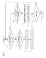
Figure 1 is a flowchart for explaining a method of
padding an image signal, using no additional information,
according to a first embodiment of the invention. Figures
2(a)-2(d) and 3(a)-3(d) are diagrams for explaining the
padding method in detail. Figures 4 and 5 are flowcharts
in which the padding method shown in figure 1 is partially
changed. Figures 6, 7, and 8 are diagrams showing how an
image is padded by the method of figure 5. Figure 9 is a
diagram for explaining additional information used in this
first embodiment. Hereinafter, the first embodiment of the
invention will be described using these figures.
First of all, a description is given of a padding
method according to the flowchart of figure 1. In this
padding method, an input image signal having an arbitrary
shape is divided into plural regions adjacent each other,
and the image signal is padded region by region in
prescribed order, i.e., each region is processed along the
flowchart of figure 1. Scanning of these regions starts
from the upper-left one and proceeds in the same order as
raster scanning. The shape of each region may be any of
triangle, rectangle, and square. In this first embodiment,
the whole region is divided into plural square regions each
comprising N×N pixels (N=8 or 16). Hereinafter, each
square region comprising N×N pixels is called a block.
With reference to figure 1, in step 12, it is decided
whether a block presently being a processing target
(hereinafter, referred to as a present block) is completely
outside an image having an arbitrary shape, i.e., an object.
When the present block is completely outside the object
("YES" in step 12), all pixels in the block are
insignificant. When the present block is not completely
outside the object ("NO" in step 12), the present block
includes significant pixels. Whether a pixel is
significant or not is decided referring to, for example, a
significant signal that is generated from a shape signal of
the object. When the significant signal is "0", the pixel
is insignificant. When the significant signal is "1", the
pixel is significant.
When the present block is not completely outside the
object ("NO" in step 12), the process proceeds to step 14.
In step 14, it is decided whether a past block adjacent to
the present block is completely outside the object. A past
block is a block that has previously been processed in the
scanning order. When the past block adjacent to the
present block is completely outside the object ("YES" in
step 14), a padding value for the past block is calculated
and obtained by a prescribed method (step 16), and sample
values of the past block are replaced with the padding
value, i.e., padded. The padding value is calculated by an
extending method in which a pixel value of a pixel inside
the object in a boundary region, i.e., a block including
the boundary of the object, is extended to the outside of
the object in the boundary region, or to an insignificant
region outside the boundary region.
When the present block is completely outside the
object in step 12, the process proceeds to step 20. In
step 20, it is decided whether the past block adjacent to
the present block is completely outside the object. When
the past block is not completely outside the object ("NO"
in step 20), a padding value for the present block is
calculated in step 22 by the same method as mentioned above,
and sample values of the present block are replaced with
the padding value, i.e., padded. After the adjacent past
block is padded in step 18, it may be decided in step 20
that the adjacent past block is not completely outside the
object. In other words, regions of reference pixels
outside the object are padded by any method and the padded
regions are included in the prediction region.
The above-mentioned process steps are repeated until
the last block is processed (step 26).
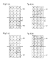
Figures 2(a)-2(d) and 3(a)-3(d) are schematic diagrams
for explaining a method of calculating a padding value.
Figures 2(a)-2(d) show a case where the present block and
the past block adjoin each other in the horizontal
direction. In figure 2(a), a block 32 is the present block
and a block 30 is the past block. Each block comprises
pixels of pixel values A∼P. Assuming that the block 30 is
completely outside the object, pixel values A∼P of pixels
in the block 32 are assigned to pixel positions in the
block 30 which are symmetrical with the block 32 across the
boundary 31 of the blocks 30 and 32, whereby the block 30
is padded. That is, mirroring is employed as a padding
function. The object boundary is shown by a line 33
between pixels A,E,I,M and pixels B,F,I,N in the block 32.
In figure 2(b), a block 35 is an object boundary
region, i.e., a block including the object boundary, and a
bock 37 is completely outside the object. In this case, as
shown in the figure, pixel values A∼P of pixels in the
block 35 are assigned to pixel positions which are
symmetrical with the block 35 across the boundary 36 of the
blocks 35 and 37, i.e., mirroring is performed, whereby the
block 37 is padded.
In figure 2(c), a block 42 is the present block, and a
block 40 is the past block. Assuming that the block 40 is
completely outside the object, as shown in the figure,
pixel values A∼P of pixels in the block 42 are assigned to
corresponding pixel positions in the block 40, i.e., the
block 40 is padded by copying.
In figure 2(d), a block 47 is the present block, and a
block 45 is the past block. Assuming that the block 47 is
completely outside the object, as shown in the figure,
pixel values A∼P of pixels in the block 45 are assigned to
corresponding pixel positions in the block 47, i.e., the
block 47 is padded by copying.
Figures 3(a)-3(d) show a case where the present block
and the past block adjoin each other in the vertical
direction.
In figure 3(a), a block 50 is the present block, and a
block 52 is the past block. Assuming that the block 50 is
completely outside the object, pixel values A∼P of pixels
in the block 52 are assigned to pixel positions which are
symmetrical with the block 52 across the block boundary 51,
i.e., the block 50 is padded by mirroring.
In figure 3(b), a block 57 is the present block, and a
block 55 is the past block. Assuming that the block 57 is
completely outside the object, pixel values A∼P of pixels
in the block 55 are assigned to pixel positions which are
symmetrical with the block 55 across the block boundary 56,
i.e., the block 57 is padded by mirroring.
In figure 3(c), a block 62 is the present block, and a
block 60 is the past block. Assuming that the block 60 is
completely outside the object, pixel values A∼P of pixels
in the block 62 are assigned to corresponding pixel
positions in the block 62, i.e., the block 60 is padded by
copying.
In figure 3(d), a block 67 is the present block, and a
block 65 is the past block. Assuming that the block 67 is
completely outside the object, pixel values A∼P of pixels
in the block 65 are assigned to corresponding pixel
positions in the block 67, i.e., the block 67 is padded by
copying.
In figures 2(a)-2(d) and 3(a)-3(d), for the blocks 32,
35, 42, 45, 52, 55, 62, and 65 positioned on the object
boundary, i.e., including the object boundary, the above-mentioned
padding process may be performed after
calculating an average of pixel values of significant
pixels in the block and assigning the average to
insignificant pixels in the block.
Further, although a 4×4 block is employed to
facilitate the description, a padding method for an N×N
block (N = arbitrary integer) is identical to the above-mentioned
method.
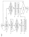
Figure 4 is a flowchart for explaining another method
of padding an image signal according to the first
embodiment, and this method is identical to the method
shown in figure 1 except that step 13 is added. In step 13,
when the present block 32 shown in figure 2(a) is not
completely inside the object, a portion of the present
block 32, which is outside the object, is padded. More
specifically, as shown in figure 2(a), when pixels A, E, I,
and M in the present block 32 are outside the object
boundary 33, i.e., outside the object, the following
padding methods are employed.
One method is to generate an average of twelve pixel
values in the block 32 other than the pixels A, E, I, and M
and assign this average to the pixels A, E, I, and M to pad
these pixels.
Another method is to pad the pixels A, E, I, and M
with pixels B, F, J, and N, which are inside the block 32
and abut on the object boundary 33, by repeating these
pixels B, F, J, and N across the object boundary 33 in the
horizontal direction. Although only the horizontal padding
is employed in the above case, it is possible to pad in
both the horizontal direction and the vertical direction.
In this case, two padding values will be provided for one
pixel, so that an average of the two padding values is
obtained as a padding value.
Figure 5 is a flowchart for explaining another method
of padding an image signal according to the first
embodiment, in which steps 14, 18, and 20 shown in figure 4
are respectively replaced with steps 15, 19, and 21 which
are restricted to process steps using the past block
adjacent to the present block in the horizontal direction.
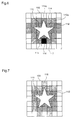
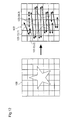
Figure 6 shows an image 108 padded according to the
process steps shown in figure 5. A region inside a star-shaped
object 110 is a significant object region, and a
region outside the significant object region is an
insignificant region comprising insignificant pixels only.
The image 108 is divided into 7×7 blocks. Cross-hatched
blocks, such as a block 112, are blocks padded in step 13
in figure 5. Parallel-hatched blocks, such as a block 114,
are blocks padded in step 19 or 24 in figure 5.
The procedure for padding the image 108 will be
described using figures 5 and 6. Initially, the block 112
is concerned. Since it is decided in step 12 that the
present block 112 is not completely outside the object, a
portion of the block 112 outside the object is padded with
the cross-hatched pattern in step 13. Since it is decided
in step 15 that the past block 112a adjacent to the present
block 112 in the horizontal direction is not completely
outside the object, step 16 not executed.
Next, the block 114 is concerned. However, this block
114 is processed prior to the block 112. Since it is
decided in step 12 that the present block 114 is completely
outside the object, step 12 is followed by step 21. Since
it is decided in step 21 that the past block 114a adjacent
to the present block 114 in the horizontal direction is not
completely outside the object, a padding value is
calculated with reference to pixel values of pixels in the
block 114a outside the object (step 22). Using the padding
value, the present block 114 is padded with the parallel-hatched
pattern (step 24).
The other blocks are padded in the same manner as
mentioned above and, finally, a block 116 is processed.
Since it is decided in step 12 that the present block 116
is completely outside the object, step 12 is followed by
step 21. Since the past block 115 adjacent to the present
block 116 in the horizontal direction is not completely
outside the object, a padding value is calculated with
reference to the past block 115 (step 22), and padding is
performed using the padding value, i.e., the present block
116 is padded with reference to the past block 115 (step
24).
When a block 117 is processed, since it is decided in
step 12 that the present block 117 is not completely
outside the object, the block 117 is padded in step 13.
Since it is decided in step 15 that the past block 116
adjacent to the block 117 in the horizontal direction is
completely outside the object ("YES" in step 15), a padding
value is calculated with reference to the pixel values in
the past block 116 in step 16, and the block 117 is padded
in step 19. That is, the block 117 is padded twice. When
plural padding values are provided for one block, padding
of the block may be performed using one of the padding
values. When the padding values are averaged, an average
may be calculated using specific padding values only.
As described above, the object of the image 108 can be
padded by extending in the horizontal direction.
Further, steps 15, 19, and 21 in figure 5 for
horizontal extension may be changed to steps for vertical
extension. In this case, an image which is vertically
extended and padded is obtained as shown in figure 7. When
the vertical extension and the horizontal extension are
combined, an image which is horizontally and vertically
extended and padded is obtained as shown in figure 8. In
this case, since padding is performed two or more times,
two or more padding values are provided. Then, all or some
of the padding values are averaged. Further, when there
are plural padding candidates, a specific padding candidate
may be used, or overwrite may be performed using the latest
padding candidate in the processing order.
Figure 9 is a schematic diagram for explaining a
manner of generating additional information when padding is
performed by any of the padding methods described with
respect to figures 1, 4, and 5. As shown in figure 9, for
a block completely outside the object, "0" is generated as
additional information and given to the block. For the
other blocks, i.e., a block having a portion inside the
object (like the block 112 shown in figures 6∼8) and a
block completely inside the object, "1" is generated as
additional information and given to these blocks.
Although two values "0" and "1" respectively showing
"completely outside the object" and "not completely outside
the object", are used as additional information, three
values showing "completely outside the object", "on the
object boundary", and "completely inside the object" may be
used as additional information.
Figure 10 is a diagram showing a manner of padding an
image signal using the additional information shown in
figure 9. Figure 11 is a flowchart of a padding method in
which additional information is generated and padding is
performed using the additional information.
A description is given of a padding method using
additional information, according to the first embodiment
of the invention.
When it is decided in step 12 that the present block
is completely outside the object, additional information
"0" is generated and obtained (step 29), followed by step
30. When the present block is not completely outside the
object ("NO" in step 12), a padding value is generated by a
prescribed method (e.g., to provide an average of
significant pixel values in the block), and insignificant
pixels in the block are padded with this padding value in
step 13, followed by step 29 wherein additional information
"1" is generated and obtained (refer to the additional
information block 120 shown in figure 10). When the last
block in the processing order has been processed, referring
to the additional information in the additional information
block 120, as shown in an image block 121 in figure 10,
blocks completely outside the object and having additional
information "1" are successively padded in the order of
arrows A1, A2, A3, ..., each arrow connecting two of these
blocks. At this time, by referring to the additional
information in the additional information block 120, pixel
values referred to for generating a padding value for the
padding process can be pixel values in a specific region.
That is, with reference to pixel values of pixels in blocks
whose additional information in the additional information
block is "1", reference pixel values can be pixel values in
an insignificant region corresponding to blocks outside the
object.
Figure 12 is a diagram showing a case where additional
information is distances between insignificant regions to
be padded, in the image signal padding method according to
the first embodiment. More specifically, in an image 122
shown in figure 12, the padding process can be performed
efficiently with reference to distances (L1, L2, L3, ...)
between blocks which are completely outside the object and
are padding targets, as shown by arrows 123-1, 123-2, 123-3,
... which show lengths of arrows A1, A2, A3, ... in
figure 10, respectively. Since significant signals exist
corresponding to the respective pixels, in order to decide
whether each block is "outside the object", "inside the
object", or "on the boundary" using the significant signals
only, all the pixels in the block must be checked. In this
first embodiment, however, since additional information is
generated in advance and padding is performed with
reference to the additional information, it is not
necessary to refer to all the significant signals in the
block.
Figure 13 is a schematic diagram for explaining a case
where additional information that shows whether a block
adjacent to a target block (present block) is an
insignificant region or not is generated for each of plural
blocks to be processed. In figure 13, four values of "0"
or "1" in each block (e.g., "0000") respectively mean
whether the upper, lower, left, and right blocks are an
insignificant region (0) or not (1). In case of a block
130, since this block is an insignificant region and its
additional information is "0100", padding is performed
referring to a padding value obtained from the lower block.
In figure 13, insignificant pixels in the lower block have
already been padded by the padding method described with
respect to figures 5 and 6, and the target block is padded
using the padding value also. In case of a block 134,
since this block has additional information of "1001",
padding values are obtained from the upper block and the
right block. Also in this case, insignificant pixels in
the upper and right blocks have already been padded using
the padding method described with respect to figures 5 and
6, and the target block is padded using the padding values
also. In this case, since two or more padding values are
provided for the block 134, an average of pixel values of
plural specific portions, for example, pixel values of
pixels adjacent to the block 134 at its upper and right
boundaries, is obtained with reference to the additional
information, as shown by the horizontal and vertical arrows
in figure 13. Alternatively, a padding value obtained from
a specific portion is employed.
Figure 14 is a schematic diagram for explaining a case
where a padding value is generated from specific reference
values with reference to additional information and padding
is performed using the padding value. In an image portion
135, when pixels in a square portion 136 are padded, i.e.,
when upper-left, lower-left, lower-right, and upper-right
portions in the square portion 136 are padded, padding is
performed by extending significant pixel values or already
padded pixel values as shown by arrows in the figure, with
reference to additional information added to blocks in
which the respective portions belong and, if necessary,
significant signals of pixels in the respective portions.
Since the upper-left and lower-right portions of the square
portion 136 are boundary portions, these portions may be
previously padded by a prescribed method like the above-mentioned
extending method. In this case, it is not
necessary to refer to the significant signals of pixels in
the respective portions.
Although additional information of four digits is used
for reference, the same processing as mentioned above can
be performed using additional information of one digit,
i.e., "0" or "1".
As described above, when the boundary region has been
padded in advance with reference to the additional
information, only the remaining insignificant region
becomes a target of padding. In this case, only the
insignificant region can be processed with reference to the
additional information, i.e., with no necessity of deciding
whether it is an insignificant region or not using
significant signals, whereby the processing efficiency is
improved.
In the padding method mentioned above, only the
boundary regions including the object boundary are padded
in advance. When the padded image is referred to, if the
referred region includes insignificant regions, i.e., when
insignificant regions are left after the padding process of
the boundary regions, these insignificant regions are
padded.
While in this first embodiment additional information
is generated with reference to significant signals,
additional information can be generated with reference to
any information with which whether a block is insignificant
or not can be decided, such as image signal, significant
signal, and side information generated when an image signal
is compressively coded. For example, an address possessed
by each block, or header information added for coding
blocks can be employed.
Furthermore, the padding process according to this
first embodiment can be performed without generating
additional information specially. That is, the padding
process may be performed with reference to, as additional
information, any information with which whether a block is
insignificant or not can be decided, such as significant
signal, image signal, and side information as mentioned
above.
Furthermore, another example of additional information
is described in the following. In a case where it is
decided that the target region is not an insignificant
region with reference to significant signals showing
whether pixel values in pixels in plural regions are
significant or not, when a past region adjacent to the
target region in prescribed processing order is an
insignificant region, the position of the past region may
be generated as additional information for padding.
[Embodiment 2]
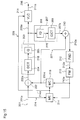
Figure 15 is a block diagram illustrating an image
signal coding apparatus according to a second embodiment of
the present invention. In figure 15, reference numeral 201
designates an input terminal to which an image signal to be
coded is applied. A first adder 202 performs subtraction
between the input signal 201a applied to the input terminal
201 and a motion compensation signal 251a supplied from a
motion compensator 215 described later, and outputs a
difference signal 202a. An encoder 203 encodes the output
202a from the first adder 202. The encoder 203 comprises a
discrete cosine transformer (DCT) 204 and a quantizer 205.
A variable length encoder (VLC) 211 performs variable
length coding to an output from the encoder 203 with
reference to a motion detecting signal 214a described later.
An output 211a of the variable length encoder 211 is output
from an output terminal 206. A decoder 207 decodes the
output from the encoder 203. This decoder 207 comprises an
inverse quantizer 208 and an inverse discrete cosine
transformer (IDCT) 209. A second adder 210 adds an output
207a from the decoder 207 and the output 215a from the
motion compensator 215. A padding unit 212 pads an output
210a from the second adder 210. A frame memory 213 stores
an output 212a from the padding unit 212. A motion
detector 214 detects a motion of the image from the present
image signal (the input signal 201) and a reference image
(an output 213a from the frame memory 213). A motion
compensator 215 outputs a motion compensating signal 215a
on the basis of a motion detecting signal 214a output from
the motion detector 214 and the reference image 213a output
from the frame memory 213.
The image signal coding apparatus so constructed
operates as follows.
An image signal having an object of an arbitrary shape
is input to the input terminal 201. The input image signal
201a is divided into plural regions adjacent each other.
In this second embodiment, the input image signal is
divided into plural blocks each having 8×8 or 16×16 pixels,
but it may be divided into arbitrarily-shaped blocks. With
reference to figure 15, a block being a target of coding
(hereinafter referred to as a target block) in the input
image signal 201a is transmitted through a line 224 and
input to the motion detector 214. At the same time, a
previously reproduced image 213a (hereinafter, referred to
as a reference image) stored in the frame memory 213 is
input to the motion detector 214. The motion detector 214
detects motion displacement information that gives a
prediction signal of the smallest error to the target block
(hereinafter, referred to as a motion vector) by block
matching or the like, and outputs a motion vector 214a.
The motion vector 214a is sent to the motion compensator
215, wherein a prediction block 215a is generated from the
reference image 213a according to the motion vector 214a.
This prediction block 215a is transmitted through a line
228 to the variable length encoder 211, converted to a
variable length code 211a, and output to the output
terminal 206. On the other hand, the target block 201a and
the prediction block 215a are sent to the first adder 202,
wherein a residual block 202a is generated. This residual
block 202a is compressed in the encoder 203 comprising the
discrete cosine transformer 204 and the quantizer 205. The
quantized data 203a is sent to the variable length encoder
211, converted to a variable length code 211a, and output
to the output terminal 206 together with side information
including motion vectors. On the other hand, the
compressed and quantized data 203a is sent to the decoder
207, wherein the data 203a is expanded. In this second
embodiment, the data 203a is inversely quantized in the
inverse quantizer 208 and then expanded to data in a
spatial region in the inverse discrete cosine transformer
209. The prediction block 215a transmitted through a line
227 is added to the expanded residual block 207a, thereby
generating a reproduced block 210a. The reproduced block
210a is input to the padding unit 212, wherein pixel values
of insignificant pixels in the reproduced block are padded
by the above-mentioned extending method in which a pixel
value inside the object in a block corresponding to a
boundary region including the object boundary is extended
to the position of an insignificant pixel outside the
object in the boundary region, or to an insignificant
region adjacent to the boundary region or an insignificant
region adjacent to the insignificant region next to the
boundary region. Alternatively, the pixel values of
insignificant pixels in the reproduced block are padded
with a padding value which is obtained by using the pixel
values of significant pixels at the boundary of the
boundary region or the pixel values of pixels in the
boundary region padded by the extending method, and the
copying function or the mirroring function described above.
The reproduced block 212a so padded is stored in the frame
memory 213. Although it is not shown in figure 15, to
decide whether pixels are significant or not, significant
signals previously encoded and decoded are employed.
The padded image stored in the frame memory 213 is as
shown in any of figures 6, 7, and 8. The padded image 213a
is sent to the motion detector 214 and to the motion
compensator 215. In this second embodiment, the ranges of
motion detection and motion compensation are limited to the
padded region (in figures 6, 7, and 8, the cross-hatched,
parallel-hatched, and dotted regions). That is, pixels
outside the padded regions are not referred to.
Further, although it is not shown in the figure, the
padding process may be performed as follows. The
additional information used for the padding method
according to the first embodiment is generated with
reference to significant signals. In the padding unit 212,
a portion having the same pattern as the cross-hatched
pattern of the block 112 shown in figure 8 is padded and,
in the motion compensator 215, a portion corresponding to
the block 119 is padded with reference to the additional
information, i.e., the fact that a block 119a on the right
of the block 119 has additional information "1".
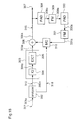
Figure 16 is a block diagram illustrating an image
signal coding apparatus according to a modification of the
second embodiment of the invention. This apparatus is
identical to the apparatus shown in figure 15 except that a
second padding unit 230 and a second frame memory 213 are
added. The second padding unit 230 performs second padding
for the output 213a from the frame memory 213, and the
second frame memory 231 stores a result 230a of the second
padding and outputs the result as a reference image 231a.
In this modification, the additional information used for
the padding method according to the first embodiment is
generated with reference to significant signals. In the
padding unit 212, a portion having the same pattern as the
cross-hatched pattern of block 112 shown in figure 8 is
padded, and this is stored in the frame memory 213. In the
second padding unit 230, a portion corresponding to the
block 119 shown in figure 8 is padded with reference to the
additional information, i.e., the fact that a block 119a on
the right of the block 119 has additional information "1",
and this is stored in the second frame memory 231.
As described above, the ranges of motion detection and
motion compensation are increased by padding regions
adjacent to the object boundary region, whereby a
prediction block with less residual, i.e., with a small
value of the residual block 202a, is provided even for an
image of great motion. Further, in the padding method
according to the invention, padding is performed block by
block with reference to additional information, delay time
in padding and arithmetic amount can be reduced.
Although discrete cosine transformation is employed in
this second embodiment, the image coding apparatus
according to this second embodiment may be applied to cases
employing shape adaptive discrete cosine transformation,
sub-band coding, and wavelet transformation are employed.
[Embodiment 3]
Figure 17 is a block diagram illustrating an image
signal decoding apparatus according to a third embodiment
of the present invention. In figure 17, an image signal
301a to be decoded is input to an input terminal 301. A
data analyzer 302 analyzes the input image signal 301a. A
decoder 303 decodes an output 302a from the analyzer 302.
The decoder 303 comprises an inverse quantizer 304 and an
inverse discrete cosine transformer 305. An adder 306 adds
an output 303a from the decoder 303 and an output 310a from
a motion compensator 310 described later. An output 306a
from the adder 306 is output from an output terminal 307.
A padding unit 308 performs padding to the output 306a from
the adder 306. A frame memory 309 stores an output 308a
from the padding unit 308. A motion compensator 310
performs motion compensation to an output 309a from the
frame memory 309.
The image signal decoding apparatus so constructed
operates as follows.
Compressed and encoded data 301a input to the input
terminal 301 is analyzed in the data analyzer 302. Then,
data in a compressed residual block 302a, which data has
been analyzed, is transmitted through a line 312 and input
to the decoder 303, and a motion vector 302b is transmitted
through a line 318 and input to the motion compensator 310.
In the decoder 303, the compressed residual block 302a is
expanded to restore the compressed block to an expanded
residual block 303a. In this third embodiment, the block
302a is subjected to inverse quantization in the inverse
quantizer 304, and a frequency region signal is transformed
to a spatial region signal in the inverse discrete cosine
transformer 305. In the motion compensator 310, an address
for accessing to the frame memory 309 is generated on the
basis of the motion vector 302a. A prediction block 309a
is generated from an image stored in the frame memory 309.
The generated prediction block 309a and the expanded
residual block 303a are added in the adder 306, generating
a reproduced block 306a. The reproduced block 306a is sent
to the output terminal 307 and, simultaneously, it is input
to the padding unit 308, wherein the reproduced image 306a
is padded using any of the padding methods according to the
first embodiment. The padded image 308a is stored in the
frame memory 309.
Although it is not shown in the figure, the padding
process may be performed as follows. In the padding unit
308, a boundary region corresponding to a block including
the object boundary, such as the block 112 shown in figure
8, is padded by a prescribed method, such as the extending
method in which a pixel value inside the object in a block
corresponding to the boundary region is extended to the
outside of the object, and additional information showing
whether each block includes a significant pixel or not is
generated. The block referred to by the motion compensator
310 is padded by a prescribed method using the additional
information and, using the padded reference block, a
prediction block is generated.
Figure 18 is a block diagram illustrating an image
signal decoding apparatus according to a modification of
this third embodiment. The apparatus shown in figure 18 is
identical to the apparatus shown in figure 17 except that a
second padding unit 330 and a second frame memory 331 are
added. The second padding unit 330 performs second padding
to the output 309a from the frame memory 309, and the
second frame memory 331 stores an output 330a from the
second padding unit 330 and outputs it as a reference image
331a. In the first padding unit 308, a boundary region
including the object boundary, like the checker-patterned
block 112 shown in figure 8, by a prescribed method, and
additional information showing whether each block includes
a significant pixel or not is generated. In the second
padding unit 330, a portion corresponding to the block 119
shown in figure 8 is padded with reference to the
additional information by a prescribed method.
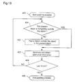
Figure 19 is a flowchart for explaining the operation
of the padding unit 308 included in the image signal
decoding apparatus shown in figure 17.
In step 401, it is decided whether a block being
processed in a prescribed order (target block) is
completely outside the object or not. When it is
completely outside the object, additional information
showing that the target block is outside the object is
generated in step 403. When the target block includes even
a portion of the object, a region outside the object in the
block is padded by a prescribed method (step 402), and
additional information showing that the target block is
inside the object or already padded is generated (step 403).
The above-mentioned procedure is repeated until the last
block is processed.
Although additional information is generated in step
403 in this third embodiment, significant signal, image
signal, or side information generated in the coding process
may be used, as it is, as additional information.
[Embodiment 4]
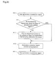
Figure 20 is a flowchart for explaining the operation
of a motion compensator in an image signal decoding
apparatus according to a fourth embodiment of the invention.
More specifically, this flowchart shows the operation of
the motion compensator 310 shown in figure 17, which
performs motion compensation for an output padded by the
padding unit 308 and stored in the frame memory 309.
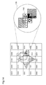
Figure 21 shows an example of operation of the motion
compensator 310.
In step 411, it is decided whether or not a block 309a
being referred to (hereinafter, referred to as a reference
block) output from the frame memory 309 is completely
inside the object or is a region that has already been
padded by the padding unit 308. When the reference block
is completely inside the object or is a region already
padded, ordinary motion compensation is executed in step
413. When the reference block includes an insignificant
region that is completely outside the object, this
insignificant region is padded by a prescribed method, such
as the extending method, using previously provided
additional information (step 412), and motion compensation
is executed using the padded block (step 413).
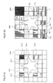
Figure 21 shows a case where the reference block
includes insignificant regions. With respect to a
reference image 501 used for motion compensation, when a
reference block 502 includes portions completely inside the
object or object boundary portions already padded 503 and
504 and insignificant portions 505 and 506 completely
outside the object as shown in figure 21, or when the
reference block is completely an insignificant region (not
shown), the insignificant portions (insignificant region)
are padded by a prescribed method, such as the extending
method, using additional information. In figure 21,
referring to pixel values 508 and 507 included in
significant blocks adjacent to the insignificant portions
505 and 506, an average of these pixel values is obtained
as a padding value, and the insignificant portions are
padded with the padding value.
Although an average of plural pixel values is used as
a padding value in figure 21, a pixel value of a block
adjacent to the target block in a specific direction may be
used as a padding value with reference to additional
information.
In the above-mentioned padding process, only the
insignificant portions (region) referred to by the motion
compensator 310 are padded, padding of a necessary region
only is realized.
In the above-mentioned image signal coding apparatus
and image signal decoding apparatus, the padding unit or
the motion compensator may be provided with a memory for
temporarily storing additional information and a padding
value required for padding.
Figures 22(a),(b) and 23(a),(b) are diagrams for
explaining an image signal coding apparatus and an image
signal decoding apparatus according to a modification of
the fourth embodiment of the invention.
An image signal coding apparatus performs motion
prediction for an input image signal, and performs motion
compensation according to the prediction. In this
modification of the fourth embodiment, a reference image
for the motion prediction, i.e., a prediction image, is
padded and, therefore, the motion prediction is performed
using a portion of the padded reference image. There is a
case where both of motion prediction and motion
compensation are performed referring to the whole image.
In this way, on the encoder side, motion compensation is
performed on the basis of motion prediction, and a
difference between an actual image and a motion-compensated
image is encoded and sent to a decoder. On the decoder
side, a motion vector detected in the encoder is obtained,
and motion compensation is performed using a sub-prediction-region
brought from the reference image. It is
rare to bring, as a reference image, an image block as
shown by a sub-prediction-region A which is referred to in
motion compensation shown in figure 23(b). In many cases,
a reference image is brought from a sub-image-block 1004
inside an image block 1000.
In this method, on the decoder side, only a minimum
region, i.e., a region corresponding to a sub-image-block
500 shown in figure 22(a), is subjected to padding and,
only when the sub-prediction-region A referred to in motion
compensation protrudes over the sub-image-block 500 and
padding for its peripheral pixels is needed, padding of
image signal is performed in motion compensation.
More specifically, since the encoder refers to the
image in both motion detection and motion compensation, the
whole image block 1000 is padded as shown in figure 23(b).
On the other hand, since the decoder performs only motion
compensation, to facilitate the padding process, an image
region to be padded is specified in the whole image block,
providing a rectangle region surrounding the target object
and a margin region outside the rectangle region. Padding
of insignificant region in the margin region is performed
in motion compensation only when it is necessary.
To be specific, on the decoder side, as shown in
figure 22(a), padding of image signal is performed for the
sub-image-block 500 in the image block 1000 using the
above-mentioned method. In motion compensation, when the
sub-reference-region A predicted in motion compensation
does not protrude from the sub-image-block 500 in the image
block 1000, motion compensation is performed with reference
to pixel values of pixels which have already been padded.
However, when the sub-reference-region A predicted in
motion compensation protrudes from the sub-image-block 700
in the image block 1000 as shown in figure 23(b), pixels in
insignificant regions in outermost blocks 710 that protrude
from the sub-image-block 700 are padded, and motion
compensation is performed using the padded pixel values.
Therefore, the padding process on the decoder side is
lightened, whereby the memory capacity and the operation
time are reduced.
The process of padding the frame-shaped region 710
outside the sub-image-block 700 will be described in detail.
As shown in figure 23(b), for a lowermost-leftmost block
720 in the block 1000, a lowermost-leftmost pixel 731 in an
upper-right block 730 is extended downward and then
horizontally toward the left, whereby the block 720 is
padded with the pixel value of the pixel 731. Further, for
blocks other than the four-corner blocks in the frame-shaped
region 710, for example, for a block 740, a pixel
750 inside the sub-image-block 700 is extended to the
outside, whereby the block 740 is padded.
[Embodiment 5]
Figures 25(a) and 25(b) are schematic diagrams for
explaining an image signal padding method according to a
fifth embodiment of the invention. In this fifth
embodiment, padding of pixel values is performed
appropriately even when a significant signal does not
correspond to an image signal (color signal).
In image processing, a color signal is composed of Y
(luminance signal) and U,V (color-difference signals).
Usually, a significant signal is of the same size as the
luminance signal. However, there is a case where the
color-difference signal is the half or quarter of the
significant signal in size. For example, in a block having
a size of 4×4 pixels, Y (luminance signal) and A
(significant signal) are as shown in figure 25(a), but U
and V (color-difference signals) have only the quarter as
many pixels as Y and A, as shown in figure 25(b). In this
case, it is necessary to match the size of A with the size
of U and V by reducing A. However, this reduction has a
risk of losing significant pixels corresponding to pixels
of U and V, resulting in a case where a boundary region has
no pixels to refer to. In this fifth embodiment, in such a
case, padding is performed by a prescribed method such as
the above-mentioned extending method, or by using a
prescribed function such as the above-mentioned copying
function and mirroring function. That is, the boundary
region is padded with a prescribed value (fixed value) or
an average of pixel values inside an object in a screen.
[Embodiment 6]
The image signal padding methods, the image signal
coding methods, and the image signal decoding methods
according to the present invention can be implemented by
programs, and the programs can be recorded on recording
media such as floppy disks for transmission, whereby these
methods are easily executed by individual computer systems.
Figure 24 shows a floppy disk according to a sixth
embodiment of the invention. A floppy disk 600 contains a
round shape disk 601, and programs of the image signal
padding method, coding method, decoding method, and motion
compensation method in the decoding method, according to
the invention, can be recorded on the disk 601.
Although a floppy disk is described in this sixth
embodiment, an optical disk may be employed in like manner.
Further, any recording media may be employed as long as
they can record programs, for example, IC cards and ROM
cassettes.
As described above, in the image signal padding method
of the present invention, not only the boundary region but
also the insignificant region adjacent to the boundary
region are padded, and motion detection and motion
compensation are performed using the padded image. In
addition, region by region padding is performed using
additional information showing whether each region includes
significant pixels or not. Therefore, in the coding and
decoding processes, a prediction signal with less
difference can be obtained even for an image of great
motion, whereby delay time and arithmetic amount in the
coding and decoding processes are significantly reduced.