JP3633159B2 - Moving picture signal encoding method and apparatus, and moving picture signal transmission method - Google Patents
Moving picture signal encoding method and apparatus, and moving picture signal transmission method Download PDFInfo
- Publication number
- JP3633159B2 JP3633159B2 JP33823696A JP33823696A JP3633159B2 JP 3633159 B2 JP3633159 B2 JP 3633159B2 JP 33823696 A JP33823696 A JP 33823696A JP 33823696 A JP33823696 A JP 33823696A JP 3633159 B2 JP3633159 B2 JP 3633159B2
- Authority
- JP
- Japan
- Prior art keywords
- motion compensation
- block
- determination
- motion
- residual
- Prior art date
- Legal status (The legal status is an assumption and is not a legal conclusion. Google has not performed a legal analysis and makes no representation as to the accuracy of the status listed.)
- Expired - Fee Related
Links
- 238000000034 method Methods 0.000 title claims description 73
- 230000008054 signal transmission Effects 0.000 title claims description 12
- 230000033001 locomotion Effects 0.000 claims description 285
- 239000013598 vector Substances 0.000 claims description 90
- 238000004364 calculation method Methods 0.000 claims description 26
- 238000010586 diagram Methods 0.000 description 12
- 238000013139 quantization Methods 0.000 description 12
- 230000005540 biological transmission Effects 0.000 description 11
- 230000003287 optical effect Effects 0.000 description 10
- 102100035353 Cyclin-dependent kinase 2-associated protein 1 Human genes 0.000 description 6
- 238000001514 detection method Methods 0.000 description 5
- 230000006866 deterioration Effects 0.000 description 4
- 230000011218 segmentation Effects 0.000 description 4
- 102100029860 Suppressor of tumorigenicity 20 protein Human genes 0.000 description 2
- 230000000694 effects Effects 0.000 description 2
- 241000255925 Diptera Species 0.000 description 1
- 230000015556 catabolic process Effects 0.000 description 1
- 230000006835 compression Effects 0.000 description 1
- 238000007906 compression Methods 0.000 description 1
- 238000006731 degradation reaction Methods 0.000 description 1
- 230000000593 degrading effect Effects 0.000 description 1
- 230000008520 organization Effects 0.000 description 1
- 239000004065 semiconductor Substances 0.000 description 1
- 230000035945 sensitivity Effects 0.000 description 1
- 238000004088 simulation Methods 0.000 description 1
- 230000000007 visual effect Effects 0.000 description 1
Images


Classifications
-
- H—ELECTRICITY
- H04—ELECTRIC COMMUNICATION TECHNIQUE
- H04N—PICTORIAL COMMUNICATION, e.g. TELEVISION
- H04N19/00—Methods or arrangements for coding, decoding, compressing or decompressing digital video signals
- H04N19/60—Methods or arrangements for coding, decoding, compressing or decompressing digital video signals using transform coding
- H04N19/61—Methods or arrangements for coding, decoding, compressing or decompressing digital video signals using transform coding in combination with predictive coding
Landscapes
- Engineering & Computer Science (AREA)
- Multimedia (AREA)
- Signal Processing (AREA)
- Compression Or Coding Systems Of Tv Signals (AREA)
- Television Signal Processing For Recording (AREA)
- Details Of Television Systems (AREA)
- Compression, Expansion, Code Conversion, And Decoders (AREA)
Description
【0001】
【産業上の利用分野】
本発明は、例えば動画像信号を光磁気ディスクや磁気テープなどの記録媒体に記録し再生してディスプレイ装置などに表示したり、テレビ会議システム,テレビ電話システムや放送用機器等のように動画像信号を伝送路を介して送信側から受信側に伝送する際に適用して好適な動画像信号符号化方式及び装置、並びに動画像信号伝送方法に関する。
【0002】
【従来の技術】
従来より、動画像信号をディジタル化して記録し又は伝送する場合、当該動画像信号はデータ量が膨大となるため、データを符号化(圧縮)している。代表的な符号化方式としては、動き補償予測符号化がある。
【0003】
動き補償予測の原理を図6に示す。
【0004】
動き補償予測符号化は、画像信号の時間軸方向の相関を利用する方法である。すなわち動き補償予測符号化は、既に復号再生されている動き予測の参照画像IRより現在の符号化対象画像IOの動きベクトルMVを推定し、復号再生されている画像信号を信号の動きに合わせて移動させ、この動き情報(動きベクトルMV)とその時の予測残差を伝送することにより、符号化に必要な情報量を圧縮する方法である。
【0005】
この動き補償予測符号化の代表的なものとしてはいわゆるMPEG(Moving Picture Expert Group) がある。これは、ISO(国際標準化機構)とIEC(国際電気標準会議)のJTC(Joint Technical Committee)1のSC(Sub Committee)29のWG(Working Group)11においてまとめられた動画像符号化方式の通称である。
【0006】
MPEGでは、1画像(フレーム又はフイールド)を16ライン×16画素で構成されるマクロブロックと呼ばれるブロックに分割し、このマクロブロック単位で動き補償予測符号化を行う。動き補償予測符号化には、大別してイントラ符号化及び非イントラ符号化の2つの方法がある。イントラ符号化は自らのマクロブロックの情報だけを使用する符号化方法であり、非イントラ符号化は自らのマクロブロックの情報と他の時刻に現れる画像より得る情報との双方の情報を用いる符号化方法である。
【0007】
MPEGの動き補償予測符号化の非イントラ符号化では、現在の符号化対象画像のマクロブロックに対応する動き予測参照画像のマクロブロックの動きベクトルを検出し、この動きベクトルに応じた予測画像と入力画像との差(動き予測の残差信号)に対してDCT(discrete cosine transform 、離散コサイン変換)を施し、得られたDCT係数値を量子化することで圧縮を行う。
【0008】
ここで、MPEGでは、現在の符号化対象画像のマクロブロックに対応する動き予測参照画像のマクロブロックの動きベクトルを検出する際に、動き予測参照画像と現在の符号化対象画像との間でマクロブロック毎にパターンマッチングを行う。具体的には、式(1) に示すように、現在の符号化対象画像のマクロブロックの輝度信号Si,jと、任意の動きベクトル(mvx,mvy)により参照される動き予測の参照画像のマクロブロックの輝度信号Ri+mvx,j+mvyとの差の絶対値和Efを求め、このEfの値を元に動きベクトルを検出する。
【0009】
![]()
【0010】
ここで、入力された画像が例えばノイズ等の影響を受けている場合に、上記のようにして動きベクトル検出を行うと、例えば画像の平坦な部分で動きベクトルを誤検出してしまったり、実際には静止している部分であるのに、上記検出された動きベクトルが(0,0)にならないことなどがある。
【0011】
すなわち、本来は上記式(1)のEfの値が最小となるはずの前記輝度信号Si,jと輝度信号Ri+mvx,j+mvyのどちらか一方あるいは双方がノイズ等の影響を受けているために、上記Efの値が最小にならないことがあり、結果として正しい動きベクトルが得られなくなることがある。
【0012】
特に、画像が静止しており、本来ならば動きベクトルが(0,0)であるはずのマクロブロックがノイズ等の影響を受けているような場合は、図7に示すように、マクロブロックに動きが無いにもかかわらず動きベクトルが(0,0)とならないために、画質が劣化する。なお、図7の例では、N個のフレームF0〜FN−1のうち、フレームFiが参照予測画像IRであり、フレームFi+jが現在の符号化対象画像IOとなっている場合を示している。ここで、画像が静止しているのであれば、現在の符号化対象画像IO内のマクロブロックMBOに対応する予測参照画像IRのマクロブロックとして、本来は動き(0,0)のマクロブロックMBRRが検出されて動きベクトルMVRも(0,0)となるべきである。これに対し、例えばノイズ等が存在することによってパターンマッチングに誤りが発生し、間違ったマクロブロックMVREが検出されると、実際とは異なる(mvx,mvy)の動きベクトルMVEが得られてしまうことが起きる。このように、画像が静止しているのに、例えばノイズ等が存在することによって(0,0)の動きベクトルMVRが得られずに、(mvx,mvy)の動きベクトルMVEが得られてしまうと、画質が劣化してしまう。
【0013】
このような問題を解決するために、マクロブロックの動きベクトルを推定して動きを補償する処理(motion compensation、以下、MCと呼ぶ)を行う際に、マクロブロック毎の輝度値を用いた所定の判定を行い、この判定結果に基づいて強制的に動きベクトルを(0,0)にするような手法が用いられている。なお、上記強制的に動きベクトルを(0,0)にする処理を、以下、NonMCと呼ぶことにする。また、上記所定の判定をMC/NonMC判定と呼ぶことにする。
【0014】
このような所定の判定(MC/NonMC判定)を行う方式としては、MPEGのいわゆるSM3(Simulation Model 3)で用いられている方式がある。
【0015】
以下に、図を用いてMPEGのSM3のMC/NonMC判定方式及び動き補償予測符号化方式を説明する。
【0016】
図8には上記MC/NonMC判定を行う動画像信号符号化装置の一例を示す。図8の動画像信号符号化装置41は、動き補償予測とDCTとを組み合わせたハイブリッド符号化方法により構成されている。
【0017】
図8において、端子42より入力した入力動画像信号S41はスキャンコンバータ43に送出される。スキャンコンバータ43では、ラスタスキャンで入力される画像信号をブロックフォーマットの信号に変換する。すなわち、図9の(A)に示すように、ラスタスキャンで入力される画像は、1ライン当りHドットのラインがVライン集められたフレームフォーマットのデータとされている。スキャンコンバータ43は、この1フレームの信号を16ラインを単位としてN個のスライスに区分する。各スライスは、図9の(B)に示すように、M個のマクロブロックに分割される。各マクロブロックは、16×16個の画素(ドット)に対応する輝度信号により構成されており、図9の(C)に示すように、この輝度信号は8×8ドットを単位とするブロックY[1]からY[4]に区分される。また、この16×16ドットの輝度信号には、8×8ドットの色差信号Cb[5]と、8×8ドットの色差信号信号Cr[6]が対応付けされる。
【0018】
上記スキャンコンバータ43によって上記ブロックフォーマットの信号に変換された動画像信号S42は、動きベクトル推定回路44、NonMEerr算出回路45、及び動画像符号化回路48に送出される。
【0019】
動きベクトル推定回路44では、順次入力される動画像信号S42の各フレームのマクロブロック毎に、参照画像記憶部46に記憶されている参照画像との間でパターンマッチングを行い(現在の符号化対象画像と参照画像との間でマクロブロック毎のパターンマッチングを行う)、このパターンマッチングの結果に基づいて動きベクトルMVを検出し、同時に動き予測残差MEerrを算出してMC/NonMC判定回路47に出力する。
【0020】
ここで、現在の符号化対象画像のマクロブロックの輝度値をSi,jとし、動き予測の参照画像の輝度値をRi,jとするとき、上記動き予測残差MEerrは式(2)を用いて求めることができる。
【0021】
![]()
【0022】
一方、NonMEerr算出回路45では、順次入力される動画像信号S42の各フレームのマクロブロック毎に、非動き補償時の残差NonMEerrを算出する。すなわち、NonMEerr算出回路45では、動画像信号S42としてフレーム毎に順次入力される現在の符号化対象画像内の各マクロブロックと、参照画像記憶部46に記憶されている参照画像のうちの動きベクトル(0,0)のマクロブロックとの間の差分をそれぞれ求め、これら差分を上記マクロブロック毎に非動き補償時の残差NonMEerrとして出力する。ここに、上記非動き補償時の残差NonMEerrは式(3)のようにして求める。
【0023】
![]()
【0024】
上述の動き予測残差MEerrと非動き補償時の残差NonMEerrとが入力されたMC/NonMC判定回路47では、例えば図10に示すような領域区分を用いて動き予測残差MEerrと非動き補償時の残差NonMEerrとの比較を行い、MC/NonMC判定を行う。すなわち図10では、縦軸に非動き補償時の残差NonMEerrを、横軸に動き予測残差MEerrをとっており、MC/NonMC判定回路47では、図10の図中点線で示すNonMEerr=MEerrの直線で比較領域を分けてMC/NonMC判定を行うのではなく、図中実線で示すような(0.1)から(0.5,1)を結ぶ直線と、(0.5,1)から(1,1.5)を結ぶ直線と、(1,1.5)から(1,2.5)を結ぶ直線と、(1,2.5)から(1.5,3)を結ぶ直線と、(1.5,3)から(2.7,3)を結ぶ直線と、NonMEerr=0.9MEerr+0.57の直線とからなる線で比較領域を分け、上記動き予測残差MEerrと非動き補償時の残差NonMEerrの値の比較において上記実線の左上側となったときにはMCと判定し、上記実線の右下側となったときにはNonMCと判定する。
【0025】
上記MC/NonMC判定回路47において、MCと判定した場合は入力された動きベクトルMV(mvx,mvy)をそのまま出力し、NonMCと判定した場合は入力された動きベクトルMV(mvx,mvy)を(0,0)に変えて出力する。当該MC/NonMC判定回路47から出力された動きベクトルMVは、そのフレームの動画像信号S42と共に動画像符号化回路(ハイブリッド符号化器)48に入力される。
【0026】
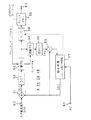
次に、図11には、図8中の動画像符号化回路(ハイブリッド符号化器)48の具体的な構成例を示す。
【0027】
この図11において、入力端子61には前記MC/NonMC判定回路47から入力される動きベクトルMVが供給される。一方、入力端子50には、当該動画像符号化回路48への入力動画像信号S60が供給される。なお、上記入力動画像信号S60は、図8の構成においてスキャンコンバータ43から供給される動画像信号S42のことである。
【0028】
また、当該動画像符号化回路48の動き補償フレーム間/内予測回路57は、画像メモリを備え、上記入力端子61からの動きベクトルMVに基づいて当該画像メモリから読み出した予測画像信号S63を出力する。
【0029】
演算器51は、上記入力端子50からの入力動画像信号S60(S42)を加算信号とし、上記動き補償フレーム間/内予測回路57からの上記予測画像信号S63を減算信号として加算処理を行うことにより、上記入力動画像信号S42と予測画像信号S63の差分を計算し、当該差分を予測残差信号S61として出力する。なお、入力動画像として、隣接フレーム間の相関が無い例えばシーンチェンジ等の信号が供給されたときは、上記予測を行わず、したがって演算器51からは入力動画像信号S60がそのまま取り出される(予測を行わない原信号として出力される)。
【0030】
次に、上記演算器51から出力された予測残差信号S61(予測を行わない時は原信号)は、DCT回路52に送られる。このDCT回路52では上記予測残差信号S61に対して2次元DCTを施す。このDCT回路52から出力されたDCT係数は、量子化回路53にてスカラー量子化される。この量子化回路53の量子化出力信号は、可変長符号化(VLC)回路58と逆量子化回路54とに送られる。VLC回路58では、上記量子化出力信号に対して例えばハフマン符号化を施す。このVLC回路58の出力信号はバッファメモリ59に送られる。当該バッファメモリ59では、伝送路に出力するビットレートを平滑化して出力端子60から出力する。また、当該バッファメモリ59がオーバーフローしそうになった時には、そのことを量子化制御情報として量子化回路53にフィードバックする。このときの量子化回路53では量子化ステップを大きくし、これにより量子化回路53から出力される情報量が小さくなり、上記バッファメモリ59ではオーバーフローの発生が防止される。なお、図11の出力端子60は、図8の出力端子49と対応している。
【0031】
一方、逆量子化回路54では、量子化回路53より供給される量子化ステップ情報q_stepに対応して、上記量子化出力信号に逆量子化処理を施す。当該逆量子化回路54の出力は、逆DCT回路55に入力され、ここで逆DCT処理されて復号された予測残差信号S62が、演算器56へ入力される。
【0032】
この演算器56にはまた、演算器51に供給されている予測画像信号S63と同一の信号が供給されている。演算器56は、上記予測残差信号S63に予測画像信号S68を加算する。これにより、局所復号した画像信号が得られる。この画像信号は、受信側での出力画像と同じ信号である。
【0033】
MPEGのSM3では、以上のようにしてMC/NonMC判定を行い、動画像符号化を行う。ここで、NonMCの場合には、動きベクトルを伝送する必要が無いため、図10に示したように、予測誤差信号が0に近い領域や、動き予測残差MEerrと非動き補償時の残差NonMEerrの値がほぼ等しいか動き予測残差MEerrが小さい領域ではNonMCを選択することで、動きベクトル分の情報量を削減できる。
【0034】
次に、動き補償予測符号化を行う際に、現在の符号化対象画像と動き予測の参照画像との間でそれぞれ対応するマクロブロックに動きは無いが、輝度値の変化は大きいような画像が入力されることがある。このような画像としては、例えば段階的に輝度値を変化させるフェードインやフェードアウトなどの処理が施された静止画像などが考えられる。なお、以下の説明では、当該静止画像においてフェードインやフェードアウトなどの処理が施されたものをフェード画像と呼ぶことにする。
【0035】
当該フェード画像のような輝度値が変化する入力画像を前記式(1)を用いたパターンマッチングによって動き補償予測符号化した場合、現在の符号化対象画像と動き予測の参照画像との間でそれぞれ対応するマクロブロックの輝度値が大きく変化しているために、本来は動きベクトル(0,0)のマクロブロックであったとしても前記Efが最小になり難く、これにより動きベクトルを誤検出してしまい、結果として再生画像にブロック歪みやモスキートノイズが目立つようになり、画質劣化が生じることになる。
【0036】
すなわち例えば前述のMPEGのSM3では、輝度値の差分の絶対値和のみで動きベクトルの検出及びMC/NonMCの判定を行っているため、実際には動き予測の参照画像と現在の符号化対象画像との間でそれぞれ対応するマクロブロックに動きが無くても、これらのマクロブロックの間で輝度値の変化が大きい場合には動きベクトルが正しく(0,0)と検出されず、本来の動きと異なるマクロブロックが参照画像のマクロブロックとして検出される可能性があり、そのために符号化効率が低下して主観画質が劣化してしまうことがある。
【0037】
このようなことから、本件出願人は、NonMC時のマクロブロックの予測残差信号を求める際に、輝度値の差分の絶対値和の代わりに、マクロブロック内の輝度値のAC成分(交流成分)の差分の絶対値和を用いて動き補償時の輝度値の絶対値和と大きさを比較して、MC/NonMC判定を行う方式(以下、ACMEと呼ぶことにする)を、既に特開平8−98187号の公報おいて開示している。
【0038】
図12には、上記ACMEを用いた動画像信号符号化装置の一例を示す。なお、この図12中のACMEerr算出回路25とMC/NonMC判定回路27を除く、入力端子22,スキャンコンバータ23,動きベクトル推定回路24、参照画像記憶部26,動画像符号化回路28,出力端子29は、各々図8の入力端子42,スキャンコンバータ43,動きベクトル推定回路44、参照画像記憶部46,動画像符号化回路48,出力端子49と対応しており、動作は全く同じであるため、説明を省略する。また、図12中の信号S22は、前記図11の動画像符号化回路28における入力動画像信号S60(図8の動画像信号S42)に対応している。
【0039】
この図12のACMEerr算出回路25において、上述の現在の符号化対象のマクロブロックと動きベクトル(0,0)の参照画像のマクロブロックのAC成分の差分の絶対値和をACMEerrとすると、当該ACMEerrは例えば以下の様な式(4)で求めることができる。
【0040】

【0041】
【0042】
図12に示した動画像信号符号化装置21においては、上述のような判定を行うことで、現在の符号化対象画像と動き予測の参照画像との間のそれぞれ対応するマクロブロックの輝度値の変化が大きく且つ動きが無い前記フェード画像のような場合であっても、動きベクトルを正しく(0,0)として得ることが出来るようになる。
【0043】
【発明が解決しようとする課題】
ところで、入力画像の平坦な部分において、前述したように現在の符号化対象画像と動き予測の参照画像との間で前記式(2) 、式(3)を用いて前記MEerrとNonMEerrとを算出したときに、各々小さい残差が得られた場合を考えてみる。
【0044】
MPEGのSM3における前記MC/NonMC判定では、これらの残差がマクロブロック間の微妙な輝度値の変化によるものなのか、ノイズの影響によるものなのか、或いは画像中の物体の一部がマクロブロックに含まれているためなのかを判断することができない。すなわち、現在の符号化対象画像と動き予測の参照画像との間のそれぞれ対応するマクロブロックが共に平坦で、動き予測残差も小さい場合に、MPEGのSM3におけるMC/NonMC判定では、符号化対象のマクロブロックが画像の一部を含んだ動きのあるマクロブロックなのか、或いはノイズを含んだ動きの無いマクロブロックなのかの判別ができない。
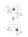
【0045】
このことを図14を用いて具体的に説明する。図14の(a)には、時間の経過と共に移動する物体OBBの画像を含む1フレームの画像の一部を示している。また、この図14の(a)に示すフレーム画像は、上記物体OBBを含むマクロブロックを除いて、ほとんど輝度値に変化のない平坦なマクロブロック(輝度値の変化が微妙にしかないマクロブロック)から構成されているが、マクロブロックMBFnにはノイズnが存在している。ただし、このノイズnを含んだマクロブロックMBFnも、ほとんど輝度値に変化のない平坦なマクロブロック(輝度値の変化が微妙にしかないマクロブロック)であるとする。
【0046】
ここで、当該図14の(a)に示すフレーム画像の符号化を行う場合に、前述したMPEGのSM3のMC/NonMC判定を用い、残差の小さい領域でNonMCが選択されるようにすると、上記ノイズnを含んだ動きの無いマクロブロックMBFnの動きベクトルについては値を(0,0)とすることはできるが、例えば上記物体OBBの画像の一部obBを含むマクロブロックMBFIのように、ほとんど輝度値に変化のない平坦なマクロブロック(輝度値の変化が微妙にしかないマクロブロック)については、本来ならば動きのあるマクロブロックとすべきものを、動きの無いマクロブロック(動きベクトル(0,0)のマクロブロック)としてしまう虞れがある。
【0047】
すなわち、このように本来ならば動きのあるマクロブロックとすべきものを、動きの無いマクロブロック(動きベクトル(0,0)のマクロブロック)としてしまうと、当該図14の(a)のフレーム画像からある時間t経過後の再生画像には、図14の(b)に示すように、上記マクロブロックMBFIに対応する位置に、上記物体OBBの一部obBが固定されたノイズobAとして残ってしまうようになる。なお、図14の(b)には、時間t経過後の物体OBAと共に、図中点線で示すように時間t経過前に物体OBBが存在した位置も示している。
【0048】
このように、物体OBBの一部obBを固定されたノイズobAとして残さないようにするためには、MCが選択されるべきである場合に誤ってNonMCが選択されないようにすればよいと考えられ、そのためにはMC/NonMC判定において例えば動き予測残差の小さい領域で、MCが選択されるべき場合に、MCが選択され易くなるようにすればよいが、前述した従来のMC/NonMC方式の場合、上記動き予測残差の小さい領域で、MCが選択されるべき場合に、MCを選択され易くすることは未だ実現されていない。
【0049】
また、従来のMC/NonMC方式の場合、動き予測残差の小さい領域で、MCを選択されやすくすると、問題が生じることがある。例えば前記マクロブロックMBFnのようにノイズnの影響を受けた平坦で動きが無く且つ予測残差が小さいマクロブロックでは、動きベクトルを誤検出してしまい、符号化効率が悪くなる虞れがあるという問題があげられる。
【0050】
これらの問題は、前述した特開平8−98187号の公報おいて開示した前記ACMEを用いるMC/NonMC判定方式においても同様である。
【0051】
そこで、本発明はこのような状況に鑑みてなされたものであり、画像の平坦部で動き予測残差の小さい場合、MCが選択されるべきときに、間違ってNonMCが選択されることを原因とする固定ノイズの発生を防止できると共に、NonMCが選択されるべきときに、間違ってMCが選択されることを原因とする画質の劣化を起こさせることなく動きベクトルを(0,0)とすることで符号化効率を向上させ、主観画質を改善し得る動画像信号符号化方法及び装置、並びに動画像信号伝送方法を提供することを目的とする。
【0052】
【課題を解決するための手段】
本発明の動画像信号符号化方法は、動画像信号を構成する画像を複数のブロックに分割し、動き補償を行ったときの上記ブロックの動きベクトル推定残差の大きさと動き補償を行わないときの上記ブロックの残差の大きさとを比較して動き補償/非動き補償判定を行い、当該判定結果に基づいて各ブロック毎に動き補償予測符号化を行う動画像信号符号化方法において、上記ブロック毎の輝度値の平均値DCと上記ブロック毎の輝度値の変化に基づいて求められる平坦さを表す値MADとを算出し、上記ブロックの輝度値の平均値DC及び上記平坦さを表す値MADをそれぞれ所定の閾値a及びbと比較した結果に基づいて、上記動き補償/非動き補償判定での大きさ比較に用いる判定領域区分を適応的に選択する際に、DC>aで且つMAD>bのときの非動き補償の判定領域区分よりも、それ以外のときの非動き補償の判定領域区分を広くすることにより、上述した課題を解決する。
【0053】
また、本発明の動画像信号符号化装置は、動画像信号を構成する画像を複数のブロックに分割するブロック分割手段と、動き補償を行ったときの上記ブロックの動きベクトル推定残差を算出する動きベクトル推定残差算出手段と、動き補償を行わないときの上記ブロックの残差を算出するブロック残差算出手段と、上記ブロック毎の輝度の平均値DCと上記ブロック毎の輝度値の変化に基づいて求められる平坦さを表す値MADとを算出する特徴量算出手段と、上記動き補償を行ったときのブロックの動きベクトル推定残差の大きさと上記動き補償を行わないときの上記ブロックの残差の大きさとを比較して動き補償/非動き補償判定を行う動き補償/非動き補償判定手段と、上記動き補償/非動き補償判定手段の判定結果に基づいて、上記各ブロック毎に動き補償予測符号化を行う動画像符号化手段とを有してなり、上記動き補償/非動き補償判定手段では、上記ブロックの輝度の平均値DC及び上記平坦さを表す値MADをそれぞれ所定の閾値a及びbと比較した結果に基づいて、上記動き補償/非動き補償判定での大きさ比較に用いる判定領域区分を適応的に選択する際に、DC>aで且つMAD>bのときの非動き補償の判定領域区分よりも、それ以外のときの非動き補償の判定領域区分を広くすることにより、上述した課題を解決する。
【0054】
さらに、本発明の動画像信号伝送方法は、動画像信号を構成する画像を複数のブロックに分割し、動き補償を行ったときの上記ブロックの動きベクトル推定残差の大きさと動き補償を行わないときの上記ブロックの残差の大きさとを比較して動き補償/非動き補償判定を行い、当該判定結果に基づいて各ブロック毎に動き補償予測符号化を行って符号化ビットストリームを生成し、当該符号化ビットストリームを伝送する動画像信号伝送方法において、上記ブロック毎の輝度の平均値DCと上記ブロック毎の輝度値の変化に基づいて求められる平坦さを表す値MADとを算出し、上記ブロックの輝度の平均値DC及び上記平坦さを表す値MADをそれぞれ所定の閾値a及びbと比較した結果に基づいて、上記動き補償/非動き補償判定での大きさ比較に用いる判定領域区分を適応的に選択する際に、DC>aで且つMAD>bのときの非動き補償の判定領域区分よりも、それ以外のときの非動き補償の判定領域区分を広くすることにより、上述した課題を解決する。
【0055】
ここで、本発明の動画像信号符号化方法及び装置、本発明の動画像信号伝送方法においては、動き補償を行わないときの上記ブロックの残差としてこのブロックのAC成分の差分を算出する。また、ブロックの輝度の平均値が低く平坦なときには、動き補償を行わない非動き補償の判定領域区分を広くするようにしている。
【0057】
すなわち本発明においては、動画像信号を動き補償予測符号化する際に、入力画像のブロック(マクロブロック)の特徴量を用いて動き補償/非動き補償の判定方式を適応的に切り替えることにより、動きが無く、ノイズの影響を受けている画像や、輝度値が大きく変化しているような画像、動きが無い全体に平坦で暗い画像に対して、非動き補償のモードを効果的に用いることが可能となる。
【0058】
【発明の実施の形態】
以下、本発明の好ましい実施の形態について、図面を参照しながら詳細に説明する。
【0059】
先ず、本発明実施例の具体的な内容の説明に先立ち、本発明の原理について説明する。
【0060】
これまでの検討の結果、現在の符号化対象画像と動き補償予測の参照画像との間のそれぞれ対応するマクロブロックにおいて、共に輝度の平均値が低く平坦であるときには、動きが無く、動きベクトルがほぼゼロであり、NonMCとなり、動き予測残差も小さくなる場合が多いことがわかっている。また、このような場合において、もし、MCが選択されるべきときに間違ってNonMCが選択されることによって、例えば画像の一部が固定されたノイズとなって残ったとしても、人間は輝度値がある程度よりも低く、暗い画像部分においては、ノイズに対しての視覚の感度が低いため、それを検知し難いこともわかっている。したがって、暗い画像部分では、もしMCが選択されるべきときに、間違ってNonMCが選択されたとしても、大きな問題ではない。
【0061】
従って、このように現在の符号化対象画像と動き補償予測の参照画像との間のそれぞれ対応するマクロブロックにおいて、共に輝度の平均値が低く平坦である場合(もしくは、「入力されたマクロブロックの平均輝度値DCと平坦さを表す値MADが、共に予め定めた閾値よりも小さい場合」)には、MC/NonMC判定において、前述した図10のような領域区分を用いて、上記動き予測残差の小さい領域がNonMCと判定され易くなるようにすれば、例え画像の一部が固定されたノイズとなって残ったとしても人間はそれを検知し難いため、主観的な画質を改善することが可能となる。
【0062】
一方、現在の符号化対象画像と動き補償予測の参照画像との間でそれぞれ対応するマクロブロックにおいて、共に輝度の平均値が高く平坦である場合には、もしMCが選択されるべきときに、間違ってNonMCが選択されることによって、前述のような画像の一部が固定されたノイズとなって残っていると、人間はそれを検知し易いことがわかっている。
【0063】
従って、このように現在の符号化対象画像と動き補償予測の参照画像との間でそれぞれ対応するマクロブロックにおいて、共に輝度の平均値が高く平坦である場合(もしくは、「入力されたマクロブロックの平均輝度値DCと平坦さを表す値MADが、共に予め定めた閾値よりも大きい場合」)には、MC/NonMC判定において、動き予測残差の小さい領域ではMC/NonMC判定を行わずに通常の動き検出を行うようにすれば、画像の一部が固定されたノイズとなって残ってしまうことを無くすことができ、画質の劣化を防ぐことが可能となる。
【0064】
そこで、本発明では、動き補償予測符号化のために動きベクトルを検出する際に、前記式(2)で得られるMEerrの最小値と前記式(3)に示すNonMEerrの値とを用い、所定の領域区分で各々の大きさを比較することでMC/NonMC判定を行い、動きの無いマクロブロックの動きベクトルを正しく(0,0)と検出しようとする方式において、現在の符号化対象画像のマクロブロックの少なくとも輝度の平均値と平坦さを表す値とに基づいて、適応的にMC/NonMC判定のための領域区分を変化させることで、MCが選択されるべきときに、間違ってNonMCが選択されることによって、画像の一部が固定されたノイズとなって残ることを無くして符号化効率を向上させることを可能にすると共に、暗い画像部分では、もしMCが選択されるべきときに、間違ってNonMCが選択されたとしても、大きな問題ではないので、例え画像の一部が固定されたノイズとなって残ったとしても主観的な画質を改善できるようにしている。
【0065】
すなわち本発明では、例えば入力画像のマクロブロックの輝度の平均値が低く平坦であり、動きが無く、動き予測残差も小さくなる場合、MC/NonMC判定において前記図10に示したような領域区分を用いて、上記動き予測残差の小さい領域がNonMCとして選択され易くすることで、例え画像の一部が固定されたノイズとなって残っても主観的な画質を改善可能にしている。
【0066】
一方、本発明では、輝度の平均値が高く平坦である場合、MC/NonMC判定において動き予測残差の小さい領域ではMC/NonMC判定を行わずに通常の動き検出を行うようにすることで、画像の一部が固定されたノイズとなって残ってしまうことを無くして、画質の劣化を防ぐことを可能にしている。
【0067】
さらに、動きベクトルを検出する時に、前記式(2)の輝度値の差分の絶対値和と同時に、前記式(4)の動きベクトル(0,0)のマクロブロックのAC成分の差分の絶対値和を用いる方式(前記ACME)でも、現在の符号化対象のマクロブロックの輝度の平均値と平坦度とに基づいて、MC/NonMC判定を適応的に制御することで、画像の一部が固定されたノイズとなって残ることを無くして符号化効率を向上させることが可能であると共に、例え画像の一部が固定されたノイズとなって残ったとしても主観的な画質を改善できる。
【0068】
すなわち、本発明にかかるMC/NonMC判定の方式を、前述した特開平8−98187号の公報にて開示されている前記ACMEを用いるMC/NonMC判定方式と組み合わせるようにすれば、現在の符号化対象画像と動き予測の参照画像のそれぞれ対応するマクロブロックの間で動きが無く、輝度値の変化が大きいような例えば前述したフェード画像に対しても、効果的にMC/NonMC判定を行うことが可能となる。
【0069】
ここで、フェード画像の平坦部や、画面全体の輝度値が低く平坦で動きが少ない画像においては、経験的に現在の符号化対象画像と動き予測の参照画像のそれぞれ対応するマクロブロックの間で、前記式(2)のMEerrと前記式(4)のACMEerrが等しいか、前記式(2)のMEerrよりも前記式(4)のACMEerrが僅かに大きい場合が多い(ACMEerrがやや大きい領域に値が集中する)ことがわかっている。このため、予測残差の小さい領域の他にも、このような領域をNonMCとすることが望ましい。
【0070】
したがって、本発明では、図1に示すように、NonMCの領域を多くした領域区分を用いて、動きベクトルを(0,0)として検出し易くしている。すなわち図1では、縦軸に前記ACMEerrを、横軸に前記動き予測残差MEerrをとっており、図中点線で示すACMEerr=MEerrの直線で比較領域を分けてMC/NonMC判定を行うのではなく、図中実線で示すような(0.y3)から(x3,y3)を結ぶ直線と、ACMEerr=MEerr+(x3−y3)の直線とからなる線で比較領域を分け、上記MEerrとACMEerrの値の比較において上記実線の左上側となったときにはMCと判定し、上記実線の右下側となったときにはNonMCと判定するようにしている。この図1の領域区分を用いることで、符号化効率を向上させて再生画像の主観的画質を向上させることができる。
【0071】
なお、上記以外の画像の場合には従来通りの前記図13に示した領域区分を用いてMC/NonMC判定を行う。
【0072】
以上のように、本発明では、入力画像の平坦部で予測残差が小さいような場合でも、主観画質を改善し、符号化効率を向上させるようにしている。
【0073】
次に、本発明実施例の具体的な内容の説明を行う。
【0074】
図2には、本発明の画像信号符号化方法及び画像信号伝送方法が適用される画像信号符号化装置1の第1の構成例を示す。本発明実施例では、動画像信号符号化装置1は動き補償予測とDCTとを組み合わせたハイブリッド符号化を行う。
【0075】
この図1において、端子2より入力した入力動画像信号S1はスキャンコンバータ3に送出される。スキャンコンバータ3では、ラスタスキャンで入力される画像信号をブロックフォーマットの信号に変換する。すなわち、前述した図9にて説明したように、当該スキャンコンバータ3は、1ライン当りHドットのラインがVライン集められたフレームフォーマットのデータとされている入力動画像信号S1の1フレームの信号を、16ラインを単位としてN個のスライスに区分し、各スライスをM個のマクロブロックに分割する。各マクロブロックは、前述同様に、16×16個の画素(ドット)に対応する輝度信号により構成されており、この輝度信号は8×8ドットを単位とするブロックY[1]からY[4]に区分され、またこの16×16ドットの輝度信号には、8×8ドットの色差信号Cb[5]と、8×8ドットの色差信号信号Cr[6]が対応付けされている。
【0076】
上記スキャンコンバータ3によって上記ブロックフォーマットの信号に変換された動画像信号S2は、動きベクトル推定回路4、NonMEerr算出回路5、特徴量算出回路6及び動画像符号化回路9に送出される。
【0077】
動きベクトル推定回路4では、順次入力される動画像信号S2の各フレームのマクロブロック毎に、参照画像記憶部7に記憶されている参照画像との間でパターンマッチングを行い(現在の符号化対象画像と参照画像との間でマクロブロック毎のパターンマッチングを行う)、このパターンマッチングの結果に基づいて動きベクトルMVを検出し、同時に前記式(2)を用いて動き予測残差MEerrを算出し、これら動きベクトルMVと動き予測残差MEerrをMC/NonMC判定回路8に出力する。
【0078】
この動画像信号符号化装置1は、1フレーム内の全てのマクロブロックの動きベクトル推定が終わったならば、現在の動画像信号S2(すなわち1フレームの画像データ)を参照画像記憶部7に記憶し、これを次に入力されてくる画像の参照画像とする。
【0079】
一方、NonMEerr算出回路5では、順次入力される動画像信号S2の各フレームのマクロブロック毎に、非動き補償時の残差NonMEerrを算出する。すなわち、NonMEerr算出回路5では、動画像信号S2としてフレーム毎に順次入力される現在の符号化対象画像内の各マクロブロックと、参照画像記憶部7に記憶されている参照画像のうちの動きベクトル(0,0)のマクロブロックとの間の差分をそれぞれ求め、これら差分を上記マクロブロック毎に非動き補償時の残差NonMEerrとして出力する。上記非動き補償時の残差NonMEerrは前記式(3)を用いて求める。
【0080】
このようにして得られた非動き補償時の残差NonMEerrは、MC/NonMC判定回路8に送られる。
【0081】
また、特徴量算出回路6では、順次入力される動画像信号S2の各フレームのマクロブロック毎に、それぞれマクロブロックの平均輝度値DCと平坦さを表す値MADとを算出する。ここで、マクロブロックの平均輝度値DCとしては、例えば次式(7)に示すように、マクロブロック内の輝度値Si,jの絶対値の和の平均を求める。
![]()
![]()
【0082】
上述した動きベクトル推定回路4からの動きベクトルMV及び動き予測残差MEerrと、NonMEerr算出回路5からの非動き補償時の残差NonMEerrと、上記特徴両算出回路6からのマクロブロックの平均輝度値DC及び平坦さを表す値MADとが入力されたMC/NonMC判定回路8では、これら供給された情報に基づいて、前述の本発明の原理にて述べたように適応的にMC/NonMC判定のための領域区分を変化させて当該MC/NonMC判定を行う。
【0083】
すなわち具体的に言うと、当該MC/NonMC判定回路8では、入力されたマクロブロックの平均輝度値DCと平坦さを表す値MADが、共に予め定めた閾値よりも小さい場合には入力動画像信号S2に対してMC/NonMC判定を行い、逆に上記閾値よりも大きい場合にはNonMCを用いずMCのみとする判定処理を行う。
【0084】
ここで、図3のフローチャートを用いて、当該MC/NonMC判定回路8における動作を説明する。
【0085】
図3において、先ずステップST1では、現在の符号化対象のフレーム内で各マクロブロックのMC/NonMC判定を開始する。
【0086】
ステップST2では、マクロブロックの平均輝度値DCと平坦さを表す値MADが、DC>aで且つMAD>bであるか否かの判定を行う。このステップST2の判定において、DC>aで且つMAD>bであるならば、通常の動き予測補償を選択し、ステップST3の処理に移る。一方、ステップST2の判定において、DC>aで且つMAD>bでない場合には、前記図10に示した領域区分を選択し、ステップST4の処理に移る。ここで、例えばa=60であり、b=384である。
【0087】
上記ステップST3では、通常の動き補償予測を行い、動きベクトルMVをそのまま出力して、ステップST7の処理に進む。なお、当該出力した動きベクトルMVは、そのマクロブロックの動画像信号S2と共に動画像符号化回路9に入力される。
【0088】
また、ステップST4では、前記図10の領域区分に従ってMC/NonMC判定を行う。このステップST4において、前記動き予測残差MEerrと非動き補償時の残差NonMEerrとの比較から、前記図10のMCの領域にある場合はステップST5の処理に進み、判定結果をMCとし、それ以外の場合はステップST6に進み、判定結果をNonMCとする。なお、図10において図中の実線上はMCの領域に含むものとする。
【0089】
ステップST5では、入力された動きベクトルMVをそのまま出力し、ステップST7の処理に進む。また、ステップST6では、入力された動きベクトルMVを(0,0)に変えて出力し、ステップST7の処理に進む。なお、これら出力した動きベクトルMVは、そのマクロブロックの動画像信号S2と共に動画像符号化回路9に入力される。
【0090】
ステップST7では、現在のマクロブロックがフレーム内の最後のマクロブロックであるか否かの判定を行う。現在のマクロブロックがフレーム内の最後のマクロブロックであると判定された場合はステップST9の処理に進み、そうでない場合はステップST2に戻り、次のマクロブロックの処理を行う。
【0091】
ステップST9では、現在の符号化対象画像のフレーム内でのMC/NonMC判定を終え、次のフレームを符号化対象画像として当該図3のフローチャートの処理を行う。
【0092】
以上のようにしてMC/NonMC判定回路8ではMC/NonMC判定を行う。
【0093】
動画像符号化回路9は、前述した図11と同じ構成を有するものであり、前記図11にて説明したのと同じ動作を行うので、ここではその説明を省略する。なお、この場合の図11の入力動画像信号S60は、図2の構成においてスキャンコンバータ3から供給される動画像信号S2のことであり、前記端子61には図2のMC/NonMC判定回路8からの動きベクトルMVが供給される。
【0094】
次に、図4には、本発明の画像信号符号化方法及び画像信号伝送方法が適用される画像信号符号化装置11の第2の構成例を示す。
【0095】
ここで、この図4に示す第2の構成例では、前記図2に示した第1の構成例のNonMEerr算出回路5の代わりにACMEerr算出回路15を用いて前記ACMEerrを算出してMC/NonMC判定を行うようにしている。このようにすることで、例えばフェード画像においても効果的なMC/NonMC判定を行えるようになる。
【0096】
なお、この図4中のACMEerr算出回路15とMC/NonMC判定回路18を除く、入力端子12,スキャンコンバータ13,動きベクトル推定回路14,特徴量算出回路16,参照画像記憶部17,動画像符号化回路19,出力端子20は、各々図2の入力端子2,スキャンコンバータ3,動きベクトル推定回路4,特徴量算出回路6,参照画像記憶部7,動画像符号化回路9,出力端子10と対応しており、動作は全く同じであるため、説明を省略する。また、図4中の信号S12は、前記図2の動画像符号化回路9における入力動画像信号S2に対応している。
【0097】
この図4のACMEerr算出回路15においては、前記式(4)、式(5)、式(6)を用いて、前記現在の符号化対象のマクロブロックと動きベクトル(0,0)の参照画像のマクロブロックのAC成分の差分の絶対値和ACMEerrを求める。
【0098】
MC/NonMC判定回路18では、入力されたマクロブロックの平均輝度値DCと平坦さを表す値MADより、入力動画像信号S12のMC/NonMC判定に用いる領域区分を選択し、選択した領域区分と入力された動き予測残差MEerrとACMEerrとから、MC/NonMCの判定を行う。
【0099】
以下、図5のフローチャートを用いて、図4のMC/NonMC判定回路18における動作を説明する。
【0100】
この図5において、先ずステップST11では、現在の符号化対象のフレーム内で各マクロブロックのMC/NonMC判定を開始する。
【0101】
ステップST12では、マクロブロックの平均輝度値DCと平坦さを表す値MADが、DC>aで且つMAD>bであるか否かの判定を行う。このステップST12の判定において、DC>aで且つMAD>bであるならば、前記図13の領域区分を選択し、ステップST13の処理に移る。一方、ステップST12の判定において、DC>aで且つMAD>bでない場合には、前記図1に示した領域区分を選択し、ステップST16の処理に移る。ここで、例えばa=60であり、b=384である。
【0102】
ステップST13では前記図13の領域区分に従ってMC/NonMC判定を行う。すなわち、当該ステップST13においては、前記図13の領域区分を用い、以下の式(9)〜式(11)の全てを満たす場合はMCと判定してステップST14の処理に進み、それ以外の場合はNonMCと判定してステップST15の処理に進む。
【0103】
【0104】
また、ステップST16では、前記図1の領域区分に従ってMC/NonMC判定を行う。すなわち、当該ステップST16においては、前記図1の領域区分を用い、以下の式(12),式(13)の全てを満たす場合はMCと判定してステップST17の処理に進み、それ以外の場合はNonMCと判定してステップST18の処理に進む。
【0105】
【0106】
ステップST19では、現在のマクロブロックがフレーム内の最後のマクロブロックであるか否かの判定を行う。このステップST19において現在のマクロブロックがフレーム内の最後のマクロブロックであると判定された場合は、ステップST20の処理に進む。そうでない場合はステップST12に戻り、次のマクロブロックの処理を行う。
【0107】
ステップST20では、現在の符号化対象画像のフレーム内でのMC/NonMC判定を終え、次のフレームを符号化対象画像として当該図5のフローチャートの処理を行う。
【0108】
以上のようにしてMC/NonMC判定回路18ではMC/NonMC判定を行う。
【0109】
図4の構成の動画像符号回路19は、前記図1の動画像符号化装置9(すなわち図11の構成)と全く同じ動作を行うので説明を省略する。なお、この場合の前記図11の入力動画像信号S60は、図4の構成においてスキャンコンバータ13から供給される動画像信号S12のことであり、前記端子61には図4のMC/NonMC判定回路18からの動きベクトルMVが供給される。
【0110】
以上のように、本発明実施例の動画像信号符号化装置においては、動画像信号を所定の予測画像信号を用いて動き補償予測符号化する際に、マクロブロック(所定映像単位)の画像信号より平均輝度値と平坦さを算出し、当該算出した輝度及び平坦さに応じて、マクロブロックの画像信号に動き補償予測を適用するか、動きを補償しない予測を適用するかを判定し、現在の画像を符号化している。
【0111】
以上の構成によれば、予測を行う際に、MC/NonMCの判定を行うことにより、符号化効率の悪くなるような動き補償を行うことが少なくなる。また、マクロブロック単位の画像信号の輝度の平均値と平坦さを表す値によって、MC/NonMCの判定を適応的に選択することにより、より効率の良いMC/NonMCの判定を行うことが可能となる。したがって、これらの効果により動画像の符号化効率を向上させ、主観画質を格段に向上させることができる。
【0112】
なお、上述の第2の構成例においては、MC/NonMCの判定のための指標として、AC成分を用いる場合について説明したが、本発明はこれに限らず、MC/NonMCの判定のための指標として色差値などを用いてもよい。この場合は、図2或いは図4において、NonMEerr算出回路5やACMEerr算出回路15に代えて、マクロブロック毎に色差値を算出する構成が用いられる。この場合のMC/NonMC判定回路は、図2或いは図4において、前記NonMEerrやACMEerrに代えて上記色差値を用いてMC/NonMC判定を行う。
【0113】
また、上述の第2の構成例においては、ACMEerrを式(4)のようにして求めたが、本発明はこれに限らず、輝度値の偏差の差分などを用いて求めても良い。
【0114】
さらに、上述の第2の構成例においては、MC/NonMC判定のための領域区分を2種類用意し、マクロブロックの特徴量に応じて適応的にその中から選択しているが、さらに多くの領域区分を用意して、多段階で適応的に切り替えるようにしても良い。
【0115】
これらにより動き補償/非動き補償の判定の効率を更に向上させることも可能である。
【0116】
次に、上述した第1、第2の構成例の動画像信号符号化装置での符号化により得られた符号化ビットストリーム(出力ビットストリーム)は、本発明に係る信号記録媒体に記録されたり、伝送路を介して伝送されることになる。
【0117】
すなわち、前述した図2や図4の動画像符号化回路9,19から出力された出力ビットストリームは、信号記録媒体の一例として光ディスク104に記録されたり、伝送路に伝送されたりする。
【0118】
前記図2及び図4において、上記出力ビットストリームを光ディスク104に記録する場合、前記出力端子10或いは20から出力された出力ビットストリーム及び量子化スケール等の後の復号化に必要な情報からなるデータ列は、誤り訂正エンコーダ(ECCエンコーダ)101によってエラーコレクションコードが付加され、変調回路102に送られる。当該変調回路102では上記誤り訂正エンコーダ101の出力に対して、所定の変調処理、例えばいわゆる8−14変調(EFM:Eight to Fourteen Modulation)或いは8−16変調等を施す。これらの変調処理は、ディジタル信号を光ディスク104の伝送特性に合わせるために、上記エンコーダされたデータ(8ビット)を14ビットや16ビットに変換する変調方式である。この変調回路102の出力は記録ヘッド103に送られ、当該記録ヘッド103にて光ディスク104に記録される。なお、図2及び図4の例では、信号記録媒体として光ディスクを例に挙げたが、ハードディスクやフレキシブルディスク等の磁気ディスク媒体や、磁気テープ等のテープ状記録媒体、ICカードや各種メモリ素子等の半導体記憶媒体等の記録媒体であってもよい。また、光ディスクとしては、物理的にピットを形成して記録がなされるディスクや、光磁気ディスクの他に、相変化型光ディスクや有機色素型光ディスク、紫外線レーザ光により記録がなされる光ディスク、多層記録膜を有する光ディスク等の各種のディスクを用いることができる。
【0119】
一方、伝送路に伝送する場合、上記データ列は、誤り訂正エンコーダ111にてエラーコレクションコードが付加され、インターフェイス回路112及び端子113を介して伝送路に出力される。なお、この伝送路としては、通常のケーブルのみならず、電波或いは光による送信も含まれる。
【0120】
上述のようにして信号記録媒体に記録されたデータ列、或いは伝送路を介して伝送されたデータ列は、従来同様の復号装置(動画像信号復号装置)にて復号再生されることになる。この場合、従来の動画像信号符号化装置を用いて符号化したものを復号再生した場合よりも良好な再生画像が得られることになる。
【0121】
【発明の効果】
上述のように本発明においては、動画像信号を動き補償予測符号化する際に、入力画像のブロック(マクロブロック)の特徴量を用いて動き補償/非動き補償(MC/NonMC)の判定方式を適応的に切り替えるようにし、また、動き予測参照画像からのマクロブロックの予測残差と動きベクトル(0,0)のマクロブロックのAC成分の差分を比較して、MC/NonMCの判定を行うようにすることにより、動きが無く、ノイズの影響を受けている画像や、輝度値が大きく変化しているような画像、動きが無い全体に平坦で暗い画像に対して、動きベクトルを強制的に(0,0)とするモードを効果的に用いることが可能となる。すなわち、本発明によれば、画像の平坦部で動き予測残差の小さい場合でも、固定ノイズの発生を防止できると共に、画質を劣化させることなく動きベクトルを(0,0)とすることで動画像信号の符号化効率を一段と向上させ、主観画質を改善し得る。
【図面の簡単な説明】
【図1】本発明実施例におけるMC/NonMC判定の領域区分を示す図である。
【図2】本発明実施例による動画像信号符号化装置の第1の構成例を示すブロック回路図である。
【図3】本発明実施例の第1の構成例におけるMC/NonMC判定の動作の説明に供するフローチャートである。
【図4】本発明実施例による動画像信号符号化装置の第2の構成を示すブロック回路図である。
【図5】本発明実施例の第2の構成例におけるMC/NonMC判定の動作の説明に供するフローチャートである。
【図6】動き補償の説明に供する図である。
【図7】動き補償と非動き補償の説明に供する図である。
【図8】MPEGのSM3の動画像信号符号化装置の構成例を示すブロック回路図である。
【図9】画像データの構造を示す図である。
【図10】MPEGのSM3におけるMC/NonMC判定の領域区分を示す図である。
【図11】動画像信号符号化装置内の動画像符号化回路の構成例を示すブロック回路図である。
【図12】AC成分の差分の絶対値和を用いてMC/NonMC判定を行う動画像信号符号化装置の構成例を示すブロック回路図である。
【図13】AC成分の差分の絶対値和を用いたMC/NonMC判定の領域区分を示す図である。
【図14】NonMCの誤検出による画質劣化の説明に供する図である。
【符号の説明】
1,11 動画像信号符号化装置、 2,12 入力端子、 3,13 スキャンコンバータ、 4,14 動きベクトル推定回路、 5 NonMCEerr 算出回路、 6,16 特徴量算出回路、 7,17 参照画像記憶部、 8,18 MC/NonMC判定回路、 9,19 動画像符号化回路、 10,20 出力端子、 15 ACMEerr算出回路[0001]
[Industrial application fields]
The present invention, for example, records a moving image signal on a recording medium such as a magneto-optical disk or a magnetic tape and reproduces it for display on a display device or the like. The present invention relates to a video signal encoding method and apparatus suitable for transmission of a signal from a transmission side to a reception side via a transmission line, and a video signal transmission method.
[0002]
[Prior art]
Conventionally, when a moving image signal is digitized and recorded or transmitted, since the moving image signal has a huge amount of data, the data is encoded (compressed). As a typical encoding method, there is motion compensation prediction encoding.
[0003]
The principle of motion compensation prediction is shown in FIG.
[0004]
Motion compensation predictive coding is a method that uses correlation in the time axis direction of an image signal. That is, the motion compensated predictive coding estimates the motion vector MV of the current encoding target image IO from the motion prediction reference image IR that has already been decoded and reproduced, and matches the decoded and reproduced image signal with the signal motion. This is a method of compressing the amount of information necessary for encoding by moving and transmitting this motion information (motion vector MV) and the prediction residual at that time.
[0005]
A typical example of this motion compensation predictive coding is a so-called MPEG (Moving Picture Expert Group). This is the common name of the video coding system summarized in WG (Working Group) 11 of SC (Sub Committee) 29 of JTC (Joint Technical Committee) 1 of ISO (International Organization for Standardization) and IEC (International Electrotechnical Commission). It is.
[0006]
In MPEG, one image (frame or field) is divided into blocks called macroblocks composed of 16 lines × 16 pixels, and motion compensation predictive coding is performed in units of the macroblocks. Motion compensation predictive coding is roughly classified into two methods: intra coding and non-intra coding. Intra coding is a coding method that uses only information of its own macroblock, and non-intra coding is coding that uses both information of its own macroblock and information obtained from images appearing at other times. Is the method.
[0007]
In non-intra coding of MPEG motion compensated predictive coding, a motion vector of a macroblock of a motion prediction reference image corresponding to a macroblock of a current encoding target image is detected, and a predicted image and an input corresponding to the motion vector are detected. DCT (discrete cosine transform, discrete cosine transform) is applied to the difference from the image (motion prediction residual signal), and compression is performed by quantizing the obtained DCT coefficient value.
[0008]
Here, in MPEG, when a motion vector of a macroblock of a motion prediction reference image corresponding to a macroblock of a current encoding target image is detected, a macro between the motion prediction reference image and the current encoding target image is detected. Pattern matching is performed for each block. Specifically, as shown in Expression (1), the luminance signal S of the macroblock of the current encoding target image. i, j And the luminance signal R of the macroblock of the reference image for motion prediction referenced by an arbitrary motion vector (mvx, mvy) i + mvx, j + mvy The absolute value sum Ef of the differences is obtained, and a motion vector is detected based on the value of Ef.
[0009]
![]()
[0010]
Here, when the input image is affected by noise or the like, if motion vector detection is performed as described above, for example, the motion vector may be erroneously detected in a flat portion of the image, However, the detected motion vector does not become (0, 0) even though it is a stationary part.
[0011]
That is, the luminance signal S that should have the minimum value of Ef in the above equation (1). i, j And luminance signal R i + mvx, j + mvy Since either or both of them are affected by noise or the like, the value of Ef may not be minimized, and as a result, a correct motion vector may not be obtained.
[0012]
In particular, when the image is stationary and a macroblock whose motion vector is supposed to be (0, 0) is affected by noise or the like, as shown in FIG. Since the motion vector does not become (0, 0) even though there is no motion, the image quality deteriorates. In the example of FIG. 7, N frames F 0 ~ F N-1 Frame F i Is the reference predicted image IR, and the frame F i + j Shows a case where the current encoding target image IO is. Here, if the image is stationary, the macroblock MB in the current encoding target image IO. O As the macroblock of the predicted reference image IR corresponding to the macroblock MB of the motion (0, 0) originally RR Is detected and the motion vector MV R Should also be (0,0). On the other hand, an error occurs in pattern matching due to, for example, noise, and the wrong macroblock MV RE Is detected, (mvx, mvy) different motion vector MV E Happens to be obtained. As described above, the motion vector MV of (0, 0) is generated due to the presence of noise or the like even though the image is stationary. R (Mvx, mvy) motion vector MV E Is obtained, the image quality deteriorates.
[0013]
In order to solve such a problem, when performing a motion compensation (hereinafter referred to as MC) process for estimating a motion vector of a macroblock and compensating for the motion, a predetermined value using a luminance value for each macroblock is used. A method is used in which a determination is made and the motion vector is forcibly set to (0, 0) based on the determination result. The process for forcibly setting the motion vector to (0, 0) is hereinafter referred to as NonMC. The predetermined determination is referred to as MC / NonMC determination.
[0014]
As a method for performing such a predetermined determination (MC / NonMC determination), there is a method used in the so-called SM3 (Simulation Model 3) of MPEG.
[0015]
In the following, an MPEG SM3 MC / NonMC determination method and a motion compensated prediction encoding method will be described with reference to the drawings.
[0016]
FIG. 8 shows an example of a moving picture signal encoding apparatus that performs the MC / NonMC determination. The moving image
[0017]
In FIG. 8, an input moving
[0018]
The moving image signal S42 converted into the block format signal by the
[0019]
The motion
[0020]
Here, the luminance value of the macroblock of the current encoding target image is set to S i, j And the luminance value of the reference image for motion prediction is R i, j Then, the motion prediction residual MEerr can be obtained using Equation (2).
[0021]
![]()
[0022]
On the other hand, the
[0023]
![]()
[0024]
In the MC /
[0025]
When the MC /
[0026]
Next, FIG. 11 shows a specific configuration example of the moving picture encoding circuit (hybrid encoder) 48 in FIG.
[0027]
In FIG. 11, the motion vector MV input from the MC /
[0028]
The motion compensation interframe /
[0029]
The
[0030]
Next, the prediction residual signal S61 output from the calculator 51 (the original signal when no prediction is performed) is sent to the
[0031]
On the other hand, the
[0032]
The
[0033]
In MPEG SM3, MC / NonMC determination is performed as described above, and moving image encoding is performed. Here, in the case of NonMC, since it is not necessary to transmit a motion vector, as shown in FIG. 10, the region where the prediction error signal is close to 0, the motion prediction residual MEerr and the residual at the time of non-motion compensation are used. By selecting NonMC in the region where the value of NonMEerr is almost equal or the motion prediction residual MEerr is small, the amount of information for the motion vector can be reduced.
[0034]
Next, when performing motion compensation predictive coding, there is no motion in the corresponding macroblocks between the current coding target image and the motion prediction reference image, but there is an image whose luminance value changes greatly. May be entered. As such an image, for example, a still image subjected to processing such as fade-in and fade-out in which the luminance value is changed stepwise can be considered. In the following description, the still image that has been subjected to processing such as fade-in and fade-out is referred to as a fade image.
[0035]
When an input image whose luminance value changes like the fade image is subjected to motion compensation prediction encoding by pattern matching using the equation (1), each of the current encoding target image and the motion prediction reference image Since the luminance value of the corresponding macro block has changed greatly, even if it is originally a macro block of a motion vector (0, 0), the Ef is unlikely to be minimized. As a result, block distortion and mosquito noise become conspicuous in the reproduced image, resulting in image quality deterioration.
[0036]
That is, for example, in the above-described MPEG SM3, motion vector detection and MC / NonMC determination are performed only with the sum of absolute values of luminance value differences. Even if there is no motion in the corresponding macroblocks between the two, the motion vector is not correctly detected as (0, 0) if the change in luminance value between these macroblocks is large, and the original motion and There is a possibility that different macroblocks are detected as macroblocks of the reference image. For this reason, the coding efficiency may be reduced and the subjective image quality may be deteriorated.
[0037]
For this reason, when determining the prediction residual signal of the macroblock at the time of NonMC, the applicant of the present invention uses the AC component (AC component) of the luminance value in the macroblock instead of the absolute value sum of the luminance value differences. The method of performing MC / NonMC determination (hereinafter referred to as ACME) has already been disclosed in Japanese Patent Application Laid-open No. Hei. This is disclosed in Japanese Patent Publication No. 8-98187.
[0038]
FIG. 12 shows an example of a moving picture signal encoding apparatus using the ACME. Except for the
[0039]
In the
[0040]
[0041]
[0042]
In the moving image
[0043]
[Problems to be solved by the invention]
By the way, in the flat part of the input image, as described above, the MEerr and NonMEerr are calculated between the current encoding target image and the motion prediction reference image using the equations (2) and (3). Let's consider the case where a small residual is obtained.
[0044]
In the MC / NonMC determination in MPEG SM3, whether these residuals are due to subtle changes in luminance values between macroblocks, the influence of noise, or some of the objects in the image are macroblocks. It is not possible to judge whether it is included in. That is, when the corresponding macroblocks between the current encoding target image and the motion prediction reference image are both flat and the motion prediction residual is small, the encoding target is determined in the MC / NonMC determination in MPEG SM3. It is impossible to discriminate whether the macro block is a macro block having a motion including a part of an image or a macro block having a motion including noise.
[0045]
This will be specifically described with reference to FIG. FIG. 14A shows an object OB that moves over time. B A part of an image of one frame including the image is shown. The frame image shown in FIG. 14A is the object OB. B Is composed of flat macroblocks with almost no change in luminance value (macroblocks whose luminance value changes only subtly). Fn There is noise n. However, the macroblock MB containing this noise n Fn Are flat macroblocks with almost no change in luminance value (macroblocks with only subtle changes in luminance value).
[0046]
Here, when the frame image shown in FIG. 14A is encoded, if the MC / NonMC determination of the MPEG SM3 described above is used and NonMC is selected in a region having a small residual, The motionless macro block MB including the noise n Fn Although the value of the motion vector of (0, 0) can be (0, 0), for example, the object OB B Part of the image B Macroblock MB containing FI For flat macroblocks that have almost no change in luminance values (macroblocks that have only subtle changes in luminance values), what should be considered as a macroblock that has movement, There is a risk that it will be a vector (0,0) macroblock).
[0047]
In other words, if a macro block that should be a motion is supposed to be a macro block without a motion (a macro block of a motion vector (0, 0)), the frame image of FIG. As shown in FIG. 14 (b), the reproduced image after a certain time t has been displayed on the macro block MB. FI At the position corresponding to the object OB B Part of B Is fixed noise ob A Will be left as. In FIG. 14B, the object OB after time t has elapsed. A In addition, as shown by the dotted line in FIG. B Also shows the location where.
[0048]
Thus, the object OB B Part of B The fixed noise ob A In order not to leave as MC, it is considered that it is only necessary to prevent NonMC from being selected by mistake when MC should be selected. For this purpose, for example, a motion prediction residual is small in MC / NonMC determination. When MC is to be selected in a region, MC may be easily selected. However, in the case of the conventional MC / NonMC method described above, MC is selected in a region where the motion prediction residual is small. It has not yet been realized that MC should be easily selected when it should be.
[0049]
Also, in the case of the conventional MC / NonMC method, there is a problem that it is likely that MC is easily selected in an area where the motion prediction residual is small. For example, the macro block MB Fn In such a macroblock that is affected by the noise n and is flat, has no motion, and has a small prediction residual, a motion vector may be erroneously detected, leading to a problem that coding efficiency may be deteriorated.
[0050]
These problems are the same in the MC / NonMC determination method using the ACME disclosed in Japanese Patent Laid-Open No. 8-98187.
[0051]
Therefore, the present invention has been made in view of such a situation, and when the motion prediction residual is small in the flat portion of the image, the non-MC is erroneously selected when the MC should be selected. Can be prevented, and when the NonMC is to be selected, the motion vector is set to (0, 0) without causing image quality degradation due to the wrong MC being selected. Accordingly, it is an object of the present invention to provide a moving image signal encoding method and apparatus and a moving image signal transmission method capable of improving encoding efficiency and improving subjective image quality.
[0052]
[Means for Solving the Problems]
The moving image signal encoding method of the present invention divides the image constituting the moving image signal into a plurality of blocks, and when motion compensation is performed and the magnitude of the motion vector estimation residual of the block is not performed. In the moving picture signal encoding method, the motion compensation / non-motion compensation determination is performed by comparing the residual size of the block with the block, and the motion compensation prediction encoding is performed for each block based on the determination result. An average value DC of luminance values for each block and a value MAD representing flatness obtained based on a change in luminance value for each block are calculated, and an average value DC of luminance values of the block and a value MAD representing flatness are calculated. DC> a and MA when adaptively selecting a determination region segment to be used for the size comparison in the motion compensation / non-motion compensation determination based on the result of comparing each with a predetermined threshold a and b. > Than the determination area division of non-motion-compensated when the b, by widening the determination area division of the non-motion compensation in other cases, to solve the problems described above.
[0053]
In addition, the moving picture signal encoding apparatus of the present invention calculates a block dividing unit that divides an image constituting a moving picture signal into a plurality of blocks and a motion vector estimation residual of the block when motion compensation is performed. Motion vector estimation residual calculation means, block residual calculation means for calculating the residual of the block when motion compensation is not performed, average value DC of luminance for each block, and change in luminance value for each block A feature amount calculating means for calculating a value MAD representing flatness obtained based on the block; a magnitude of a motion vector estimation residual of the block when the motion compensation is performed; and a residual of the block when the motion compensation is not performed. Based on the determination result of the motion compensation / non-motion compensation determination means for comparing the magnitude of the difference and making the motion compensation / non-motion compensation determination, and the determination result of the motion compensation / non-motion compensation determination means, Moving image coding means for performing motion compensation prediction coding for each block. In the motion compensation / non-motion compensation determination means, an average value DC of luminance of the block and a value MAD representing the flatness are obtained. DC> a and MAD> b when adaptively selecting a determination area segment to be used for size comparison in the motion compensation / non-motion compensation determination based on the result of comparison with predetermined threshold values a and b, respectively. The above-described problem is solved by making the non-motion compensation determination area section at other times wider than the non-motion compensation determination area section at this time.
[0054]
Furthermore, the moving image signal transmission method of the present invention does not perform motion compensation and the magnitude of the motion vector estimation residual of the block when the image constituting the moving image signal is divided into a plurality of blocks and motion compensation is performed. A motion compensation / non-motion compensation determination by comparing the residual magnitude of the block at the time, and generating a coded bitstream by performing motion compensation prediction encoding for each block based on the determination result, In the moving image signal transmission method for transmitting the encoded bitstream, the average value DC of the luminance for each block and the value MAD representing flatness obtained based on the change of the luminance value for each block are calculated, Based on the result of comparing the average value DC of the luminance of the block and the value MAD representing the flatness with predetermined threshold values a and b, respectively, the large value in the motion compensation / non-motion compensation determination is obtained. When adaptively selecting the judgment area section used for the comparison, the non-motion compensation judgment area section at other times than the non-motion compensation judgment area section when DC> a and MAD> b. By widening, the above-described problems are solved.
[0055]
Here, in the moving picture signal encoding method and apparatus of the present invention and the moving picture signal transmission method of the present invention, the difference of the AC component of this block is calculated as the residual of the block when motion compensation is not performed. Further, when the average value of the luminance of the block is low and flat, the determination region section for non-motion compensation that does not perform motion compensation is widened.
[0057]
That is, in the present invention, when motion compensation prediction coding is performed on a moving image signal, the motion compensation / non-motion compensation determination method is adaptively switched using the feature amount of the block (macroblock) of the input image, Use non-motion compensation mode effectively for images that are not moving and affected by noise, images that have a large change in brightness, or images that are flat and dark with no motion. Is possible.
[0058]
DETAILED DESCRIPTION OF THE INVENTION
Hereinafter, preferred embodiments of the present invention will be described in detail with reference to the drawings.
[0059]
First, the principle of the present invention will be described prior to the description of the specific contents of the embodiment of the present invention.
[0060]
As a result of the examination so far, in the corresponding macroblocks between the current encoding target image and the reference image for motion compensated prediction, when both the average values of the luminance are low and flat, there is no motion and the motion vector is It is known that it is almost zero, becomes NonMC, and the motion prediction residual is often small. Also, in such a case, if a non-MC is selected by mistake when the MC is to be selected, even if a part of the image remains as a fixed noise, for example, the human will It is also known that it is difficult to detect in a dark image portion because the visual sensitivity to noise is low in a dark image portion. Therefore, in the dark image portion, if MC is to be selected and NonMC is selected by mistake, it is not a big problem.
[0061]
Therefore, when the average luminance value is low and flat in each of the corresponding macroblocks between the current encoding target image and the reference image for motion compensation prediction (or “ When the average luminance value DC and the flatness value MAD are both smaller than a predetermined threshold value ”)), the above-described motion prediction residual is used in the MC / NonMC determination by using the region segmentation as shown in FIG. If it is easy for a region with a small difference to be determined as NonMC, even if a part of the image remains as a fixed noise, it is difficult for humans to detect it, so that the subjective image quality is improved. Is possible.
[0062]
On the other hand, in the macroblocks corresponding to the current encoding target image and the motion compensated prediction reference image, if both the average luminance values are high and flat, if MC is to be selected, It is known that if a non-MC is selected by mistake and a part of the image as described above remains as fixed noise, it is easy for humans to detect it.
[0063]
Accordingly, in the macroblocks corresponding to the current encoding target image and the reference image for motion compensated prediction as described above, when the average value of the luminance is both high and flat (or “the input macroblock When the average luminance value DC and the value MAD representing flatness are both larger than a predetermined threshold value ”), MC / NonMC determination is normally performed without performing MC / NonMC determination in an area where the motion prediction residual is small. If motion detection is performed, it is possible to eliminate a part of an image from remaining as fixed noise, and to prevent deterioration of image quality.
[0064]
Therefore, in the present invention, when detecting a motion vector for motion compensated predictive coding, the minimum value of MEerr obtained by the equation (2) and the value of NonMEerr shown in the equation (3) are used. MC / NonMC determination is performed by comparing the respective sizes in the region segments of the region, and in a method for detecting the motion vector of a macroblock having no motion correctly as (0, 0), When MC is to be selected by appropriately changing the region division for MC / NonMC determination based on at least the average value of luminance and the value representing flatness of the macroblock, the MC may be incorrectly By being selected, it is possible to improve the coding efficiency without leaving a part of the image as fixed noise, and in the dark image part, if M Even if NonMC is selected by mistake when it should be selected, it is not a big problem, so that even if a part of the image remains as fixed noise, the subjective image quality can be improved. ing.
[0065]
That is, in the present invention, for example, when the average value of the luminance of the macroblock of the input image is low and flat, there is no motion, and the motion prediction residual is also small, the region segmentation as shown in FIG. By using this, it is possible to improve the subjective image quality even if a part of the image remains as a fixed noise by making it easy to select the region having the small motion prediction residual as NonMC.
[0066]
On the other hand, in the present invention, when the average value of brightness is high and flat, normal motion detection is performed without performing MC / NonMC determination in an area where the motion prediction residual is small in MC / NonMC determination. It is possible to prevent deterioration of image quality by eliminating a part of the image remaining as fixed noise.
[0067]
Further, when detecting the motion vector, the absolute value of the difference between the AC components of the macroblock of the motion vector (0, 0) of the equation (4) is simultaneously with the absolute value sum of the differences of the luminance values of the equation (2). Even in the method using the sum (ACME), a part of the image is fixed by adaptively controlling MC / NonMC determination based on the average luminance value and flatness of the current macroblock to be encoded. It is possible to improve the coding efficiency by eliminating the remaining noise, and to improve the subjective image quality even if a part of the image remains as a fixed noise.
[0068]
That is, if the MC / NonMC determination method according to the present invention is combined with the MC / NonMC determination method using the ACME disclosed in the above-mentioned Japanese Patent Application Laid-Open No. 8-98187, the current encoding is performed. For example, the MC / NonMC determination can be effectively performed even for the above-described fade image in which there is no motion between the corresponding macroblocks of the target image and the motion prediction reference image and the change in the luminance value is large. It becomes possible.
[0069]
Here, in a flat portion of a fade image, or in an image with a low brightness value and a small amount of motion of the entire screen, it is empirically determined between the corresponding macroblocks of the current encoding target image and the motion prediction reference image. In many cases, the MEerr of the formula (2) is equal to the ACMEerr of the formula (4), or the ACMEerr of the formula (4) is slightly larger than the MEerr of the formula (2) (in a region where the ACMEerr is slightly larger). Value is concentrated). For this reason, in addition to a region having a small prediction residual, it is desirable to set such a region as NonMC.
[0070]
Therefore, in the present invention, as shown in FIG. 1, the motion vector is easily detected as (0, 0) by using a region segment in which the region of NonMC is increased. That is, in FIG. 1, the ACMEerr is taken on the vertical axis and the motion prediction residual MEerr is taken on the horizontal axis, and MC / NonMC determination is performed by dividing the comparison region by a straight line ACMEerr = MEerr shown by a dotted line in the figure. Rather, the comparison area is divided by a line consisting of a straight line connecting (0.y3) to (x3, y3) as shown by a solid line in the figure and a straight line of ACMEerr = MEerr + (x3−y3), and the above MEerr and ACMEerr In the comparison of values, MC is determined when the value is on the upper left side of the solid line, and NonMC is determined when the value is on the lower right side of the solid line. By using the region division of FIG. 1, it is possible to improve the coding efficiency and improve the subjective image quality of the reproduced image.
[0071]
In the case of an image other than the above, MC / NonMC determination is performed using the conventional area segmentation shown in FIG.
[0072]
As described above, according to the present invention, even when the prediction residual is small in the flat portion of the input image, the subjective image quality is improved and the coding efficiency is improved.
[0073]
Next, specific contents of the embodiment of the present invention will be described.
[0074]
FIG. 2 shows a first configuration example of an image
[0075]
In FIG. 1, an input moving
[0076]
The moving image signal S2 converted into the block format signal by the
[0077]
The motion
[0078]
When the motion vector estimation of all macroblocks in one frame is completed, the moving image
[0079]
On the other hand, the
[0080]
The non-motion compensation residual NonMEerr obtained in this way is sent to the MC /
[0081]
Further, the feature
![]()
![]()
[0082]
The motion vector MV and motion prediction residual MEerr from the motion
[0083]
Specifically, in the MC /
[0084]
Here, the operation of the MC /
[0085]
In FIG. 3, first, in step ST1, MC / NonMC determination of each macroblock is started within the current encoding target frame.
[0086]
In step ST2, it is determined whether or not the average luminance value DC of the macroblock and the value MAD representing flatness are DC> a and MAD> b. If DC> a and MAD> b in the determination of step ST2, normal motion prediction compensation is selected, and the process proceeds to step ST3. On the other hand, if it is determined in step ST2 that DC> a and MAD> b are not satisfied, the region segment shown in FIG. 10 is selected, and the process proceeds to step ST4. Here, for example, a = 60 and b = 384.
[0087]
In step ST3, normal motion compensation prediction is performed, the motion vector MV is output as it is, and the process proceeds to step ST7. The output motion vector MV is input to the moving
[0088]
In step ST4, MC / NonMC determination is performed according to the area division of FIG. In this step ST4, from the comparison of the motion prediction residual MEerr and the residual NonMEerr at the time of non-motion compensation, if it is in the MC region of FIG. 10, the process proceeds to step ST5, where the determination result is MC Otherwise, the process proceeds to step ST6, and the determination result is set to NonMC. In FIG. 10, the solid line in FIG. 10 is included in the MC region.
[0089]
In step ST5, the input motion vector MV is output as it is, and the process proceeds to step ST7. In step ST6, the input motion vector MV is changed to (0, 0) and output, and the process proceeds to step ST7. The output motion vector MV is input to the moving
[0090]
In step ST7, it is determined whether or not the current macroblock is the last macroblock in the frame. If it is determined that the current macroblock is the last macroblock in the frame, the process proceeds to step ST9. If not, the process returns to step ST2 to process the next macroblock.
[0091]
In step ST9, the MC / NonMC determination in the frame of the current encoding target image is finished, and the processing of the flowchart of FIG. 3 is performed with the next frame as the encoding target image.
[0092]
As described above, the MC /
[0093]
The moving
[0094]
Next, FIG. 4 shows a second configuration example of the image signal encoding device 11 to which the image signal encoding method and the image signal transmission method of the present invention are applied.
[0095]
Here, in the second configuration example shown in FIG. 4, the ACMEerr is calculated by using the ACMEerr calculation circuit 15 instead of the
[0096]
Except for the ACMEerr calculation circuit 15 and the MC /
[0097]
In the ACMEerr calculation circuit 15 of FIG. 4, the current encoding target macroblock and the reference image of the motion vector (0, 0) are used by using the equations (4), (5), and (6). The absolute value sum ACMEerr of the AC component differences of the macroblocks is obtained.
[0098]
The MC /
[0099]
Hereinafter, the operation of the MC /
[0100]
In FIG. 5, first, in step ST11, MC / NonMC determination of each macroblock is started within the current encoding target frame.
[0101]
In step ST12, it is determined whether the average luminance value DC of the macroblock and the value MAD representing flatness are DC> a and MAD> b. If it is determined in step ST12 that DC> a and MAD> b, the region section shown in FIG. 13 is selected, and the process proceeds to step ST13. On the other hand, if it is determined in step ST12 that DC> a and MAD> b are not satisfied, the region segment shown in FIG. 1 is selected, and the process proceeds to step ST16. Here, for example, a = 60 and b = 384.
[0102]
In step ST13, MC / NonMC determination is performed according to the area division of FIG. That is, in the step ST13, the region classification of FIG. 13 is used, and when all of the following formulas (9) to (11) are satisfied, it is determined as MC and the process proceeds to step ST14. Is determined to be NonMC, and the process proceeds to step ST15.
[0103]
[0104]
In step ST16, MC / NonMC determination is performed in accordance with the area division of FIG. That is, in the step ST16, the region classification of FIG. 1 is used, and if all of the following formulas (12) and (13) are satisfied, it is determined as MC and the process proceeds to step ST17. Is determined to be NonMC, and the process proceeds to step ST18.
[0105]
[0106]
In step ST19, it is determined whether or not the current macroblock is the last macroblock in the frame. If it is determined in step ST19 that the current macroblock is the last macroblock in the frame, the process proceeds to step ST20. Otherwise, the process returns to step ST12 and the next macroblock is processed.
[0107]
In step ST20, the MC / NonMC determination within the frame of the current encoding target image is finished, and the processing of the flowchart of FIG. 5 is performed using the next frame as the encoding target image.
[0108]
As described above, the MC /
[0109]
The moving
[0110]
As described above, in the moving image signal encoding apparatus of the embodiment of the present invention, when a moving image signal is motion-compensated and predicted using a predetermined predicted image signal, the image signal of a macroblock (predetermined video unit) The average luminance value and flatness are calculated, and whether to apply motion compensation prediction or non-motion compensation prediction to the image signal of the macroblock according to the calculated luminance and flatness is determined. The image is encoded.
[0111]
According to the above configuration, by performing MC / NonMC determination at the time of prediction, motion compensation that deteriorates the encoding efficiency is reduced. In addition, it is possible to perform more efficient MC / NonMC determination by adaptively selecting the MC / NonMC determination based on the average value and the flatness of the luminance value of the image signal in units of macroblocks. Become. Therefore, it is possible to improve the coding efficiency of moving images by these effects and to significantly improve the subjective image quality.
[0112]
In the above-described second configuration example, the case where the AC component is used as the index for determining MC / NonMC has been described. However, the present invention is not limited to this, and the index for determining MC / NonMC. A color difference value or the like may be used. In this case, instead of the
[0113]
Further, in the above-described second configuration example, ACMEerr is obtained as shown in Expression (4), but the present invention is not limited to this, and may be obtained using a difference in luminance value deviation or the like.
[0114]
Furthermore, in the above-described second configuration example, two types of area divisions for MC / NonMC determination are prepared and adaptively selected according to the feature amount of the macroblock. Area divisions may be prepared and adaptively switched in multiple stages.
[0115]
Thus, it is possible to further improve the efficiency of determination of motion compensation / non-motion compensation.
[0116]
Next, the encoded bit stream (output bit stream) obtained by encoding with the moving image signal encoding apparatus of the first and second configuration examples described above is recorded on the signal recording medium according to the present invention. Then, it is transmitted through the transmission path.
[0117]
That is, the output bit stream output from the moving
[0118]
2 and 4, when the output bit stream is recorded on the
[0119]
On the other hand, when transmitting to the transmission line, the error correction code is added to the data string by the
[0120]
The data string recorded on the signal recording medium as described above, or the data string transmitted through the transmission path is decoded and reproduced by a decoding apparatus (moving image signal decoding apparatus) similar to the conventional one. In this case, a better reproduced image can be obtained than when the image encoded using the conventional moving image signal encoding device is decoded and reproduced.
[0121]
【The invention's effect】
As described above, in the present invention, a motion compensation / non-motion compensation (MC / NonMC) determination method using a feature amount of a block (macroblock) of an input image when motion compensation prediction coding is performed on a moving image signal. MC / NonMC is determined by comparing the prediction residual of the macroblock from the motion prediction reference image with the AC component difference of the macroblock of the motion vector (0, 0). By doing so, the motion vector is compulsory for images that have no motion and are affected by noise, images that have a large change in luminance value, and images that are flat and dark overall. It is possible to effectively use the mode (0, 0). That is, according to the present invention, even when the motion prediction residual is small in the flat portion of the image, the generation of fixed noise can be prevented and the motion vector is set to (0, 0) without degrading the image quality. The encoding efficiency of the image signal can be further improved, and the subjective image quality can be improved.
[Brief description of the drawings]
FIG. 1 is a diagram showing an area classification of MC / NonMC determination in an embodiment of the present invention.
FIG. 2 is a block circuit diagram showing a first configuration example of a moving picture signal encoding apparatus according to an embodiment of the present invention.
FIG. 3 is a flowchart for explaining an operation of MC / NonMC determination in the first configuration example of the embodiment of the present invention;
FIG. 4 is a block circuit diagram showing a second configuration of the moving picture signal encoding apparatus according to the embodiment of the present invention.
FIG. 5 is a flowchart for explaining an operation of MC / NonMC determination in the second configuration example of the embodiment of the present invention;
FIG. 6 is a diagram for explaining motion compensation.
FIG. 7 is a diagram for explaining motion compensation and non-motion compensation.
FIG. 8 is a block circuit diagram showing a configuration example of a moving picture signal encoding apparatus of MPEG SM3.
FIG. 9 is a diagram illustrating a structure of image data.
FIG. 10 is a diagram showing area classification of MC / NonMC determination in SM3 of MPEG.
FIG. 11 is a block circuit diagram illustrating a configuration example of a moving image encoding circuit in the moving image signal encoding device.
FIG. 12 is a block circuit diagram illustrating a configuration example of a moving image signal encoding apparatus that performs MC / NonMC determination using an absolute value sum of AC component differences.
FIG. 13 is a diagram showing an area classification for MC / NonMC determination using the sum of absolute values of differences of AC components.
FIG. 14 is a diagram for explaining image quality deterioration due to erroneous detection of NonMC.
[Explanation of symbols]
DESCRIPTION OF
Claims (9)
上記ブロック毎の輝度値の平均値DCと上記ブロック毎の輝度値の変化に基づいて求められる平坦さを表す値MADとを算出し、
上記ブロックの輝度値の平均値DC及び上記平坦さを表す値MADをそれぞれ所定の閾値a及びbと比較した結果に基づいて、上記動き補償/非動き補償判定での大きさ比較に用いる判定領域区分を適応的に選択する際に、DC>aで且つMAD>bのときの非動き補償の判定領域区分よりも、それ以外のときの非動き補償の判定領域区分を広くする
ことを特徴とする動画像信号符号化方法。Compare the size of the motion vector estimation residual of the block when motion compensation is performed by dividing the image constituting the video signal into multiple blocks and the size of the residual of the block when motion compensation is not performed In the moving image signal encoding method for performing motion compensation / non-motion compensation determination and performing motion compensation prediction encoding for each block based on the determination result,
Calculating an average value DC of luminance values for each block and a value MAD representing flatness determined based on a change in luminance value for each block ;
A determination region used for size comparison in the motion compensation / non-motion compensation determination based on the result of comparing the average value DC of the luminance value of the block and the value MAD representing the flatness with predetermined threshold values a and b, respectively. When selecting a section adaptively, the determination area section for non-motion compensation at other times is wider than the determination area section for non-motion compensation when DC> a and MAD> b. A video signal encoding method characterized by the above.
ことを特徴とする請求項1記載の動画像信号符号化方法。2. The moving picture signal encoding method according to claim 1, wherein a difference between AC components of the block is calculated as a residual of the block when the motion compensation is not performed.
ことを特徴とする請求項1記載の動画像信号符号化方法。The moving image signal encoding method according to claim 1 , wherein when DC> a and MAD> b, the motion compensation / non-motion compensation determination is determined as the motion compensation .
動き補償を行ったときの上記ブロックの動きベクトル推定残差を算出する動きベクトル推定残差算出手段と、
動き補償を行わないときの上記ブロックの残差を算出するブロック残差算出手段と、
上記ブロック毎の輝度の平均値DCと上記ブロック毎の輝度値の変化に基づいて求められる平坦さを表す値MADとを算出する特徴量算出手段と、
上記動き補償を行ったときのブロックの動きベクトル推定残差の大きさと上記動き補償を行わないときの上記ブロックの残差の大きさとを比較して動き補償/非動き補償判定を行う動き補償/非動き補償判定手段と、
上記動き補償/非動き補償判定手段の判定結果に基づいて、上記各ブロック毎に動き補償予測符号化を行う動画像符号化手段とを有してなり、
上記動き補償/非動き補償判定手段では、上記ブロックの輝度の平均値DC及び上記平坦さを表す値MADをそれぞれ所定の閾値a及びbと比較した結果に基づいて、上記動き補償/非動き補償判定での大きさ比較に用いる判定領域区分を適応的に選択する際に、DC>aで且つMAD>bのときの非動き補償の判定領域区分よりも、それ以外のときの非動き補償の判定領域区分を広くする
ことを特徴とする動画像信号符号化装置。Block dividing means for dividing an image constituting the moving image signal into a plurality of blocks;
A motion vector estimation residual calculating means for calculating a motion vector estimation residual of the block when performing motion compensation;
Block residual calculation means for calculating the residual of the block when motion compensation is not performed;
Feature amount calculating means for calculating an average value DC of luminance for each block and a value MAD representing flatness obtained based on a change in luminance value for each block ;
Motion compensation / non-motion compensation determination is performed by comparing the magnitude of the motion vector estimation residual of the block when the motion compensation is performed with the magnitude of the residual of the block when the motion compensation is not performed. Non-motion compensation determination means;
Based on the determination result of the motion compensation / non-motion compensation determination means, and moving picture encoding means for performing motion compensation prediction encoding for each block,
In the motion compensation / non-motion compensation determination means, the motion compensation / non-motion compensation is based on the result of comparing the average value DC of the luminance of the block and the value MAD representing the flatness with predetermined threshold values a and b, respectively. When adaptively selecting the determination region segment used for the size comparison in the determination, the non-motion compensation determination region segment other than the non-motion compensation determination region segment when DC> a and MAD> b. A moving image signal encoding apparatus characterized by widening a determination area section .
ことを特徴とする請求項4記載の動画像信号符号化装置。5. The moving picture signal encoding apparatus according to claim 4, wherein the block residual calculating means calculates an AC component difference of the block as a residual of the block when the motion compensation is not performed.
ことを特徴とする請求項4記載の動画像信号符号化装置。The moving image signal encoding apparatus according to claim 4, wherein the motion compensation / non-motion compensation determination means determines the motion compensation when DC> a and MAD> b .
上記ブロック毎の輝度の平均値DCと上記ブロック毎の輝度値の変化に基づいて求められる平坦さを表す値MADとを算出し、
上記ブロックの輝度の平均値DC及び上記平坦さを表す値MADをそれぞれ所定の閾値 a及びbと比較した結果に基づいて、上記動き補償/非動き補償判定での大きさ比較に用いる判定領域区分を適応的に選択する際に、DC>aで且つMAD>bのときの非動き補償の判定領域区分よりも、それ以外のときの非動き補償の判定領域区分を広くする
ことを特徴とする動画像信号伝送方法。Compare the size of the motion vector estimation residual of the block when motion compensation is performed by dividing the image constituting the video signal into multiple blocks and the size of the residual of the block when motion compensation is not performed Then, motion compensation / non-motion compensation determination is performed, motion compensation predictive coding is performed for each block based on the determination result, an encoded bit stream is generated, and the encoded bit stream is transmitted. In the method
Calculating a value MAD representing the flatness obtained on the basis of a change in luminance of the upper Symbol each block and the average value DC of luminance for each said block,
Determination area segment used for size comparison in the motion compensation / non-motion compensation determination based on the result of comparing the average value DC of luminance of the block and the value MAD representing the flatness with predetermined threshold values a and b , respectively. When selecting DC, a non-motion-compensation determination region segment is set wider than the non-motion-compensation determination region segment when DC> a and MAD> b. A moving image signal transmission method characterized by the above.
ことを特徴とする請求項7記載の動画像信号伝送方法。8. The moving image signal transmission method according to claim 7, wherein a difference between AC components of the block is calculated as a residual of the block when the motion compensation is not performed.
ことを特徴とする請求項7記載の動画像信号伝送方法。The moving picture signal transmission method according to claim 7 , wherein when DC> a and MAD> b, the motion compensation / non-motion compensation determination is determined as the motion compensation .
Priority Applications (2)
| Application Number | Priority Date | Filing Date | Title |
|---|---|---|---|
| JP33823696A JP3633159B2 (en) | 1996-12-18 | 1996-12-18 | Moving picture signal encoding method and apparatus, and moving picture signal transmission method |
| US08/991,517 US6040865A (en) | 1996-12-18 | 1997-12-16 | Image signal coding method and apparatus, image signal transmission method, and signal recording medium |
Applications Claiming Priority (1)
| Application Number | Priority Date | Filing Date | Title |
|---|---|---|---|
| JP33823696A JP3633159B2 (en) | 1996-12-18 | 1996-12-18 | Moving picture signal encoding method and apparatus, and moving picture signal transmission method |
Publications (2)
| Publication Number | Publication Date |
|---|---|
| JPH10178645A JPH10178645A (en) | 1998-06-30 |
| JP3633159B2 true JP3633159B2 (en) | 2005-03-30 |
Family
ID=18316217
Family Applications (1)
| Application Number | Title | Priority Date | Filing Date |
|---|---|---|---|
| JP33823696A Expired - Fee Related JP3633159B2 (en) | 1996-12-18 | 1996-12-18 | Moving picture signal encoding method and apparatus, and moving picture signal transmission method |
Country Status (2)
| Country | Link |
|---|---|
| US (1) | US6040865A (en) |
| JP (1) | JP3633159B2 (en) |
Families Citing this family (20)
| Publication number | Priority date | Publication date | Assignee | Title |
|---|---|---|---|---|
| JP3633159B2 (en) * | 1996-12-18 | 2005-03-30 | ソニー株式会社 | Moving picture signal encoding method and apparatus, and moving picture signal transmission method |
| JP2000134631A (en) * | 1998-10-23 | 2000-05-12 | Canon Inc | Device and method for image encoding, device and method for image decoding, and computer readable storage medium |
| EP1126729A1 (en) * | 2000-02-18 | 2001-08-22 | STMicroelectronics S.r.l. | A process for estimating the noise level in sequences of images and a device therefor |
| KR100961760B1 (en) * | 2002-08-13 | 2010-06-07 | 퀄컴 인코포레이티드 | Motion estimation method and apparatus referencing discrete cosine transform coefficients |
| JP3897684B2 (en) * | 2002-11-22 | 2007-03-28 | キヤノン株式会社 | Image recording method |
| KR20050119422A (en) * | 2004-06-16 | 2005-12-21 | 삼성전자주식회사 | Method and apparatus for estimating noise of input image based on motion compenstion and, method for eliminating noise of input image and for encoding video using noise estimation method, and recording medium for storing a program to implement the method |
| CN100359953C (en) * | 2004-09-08 | 2008-01-02 | 华为技术有限公司 | Image Chroma Prediction Method Based on Intra-Frame Coding |
| JP4271115B2 (en) * | 2004-09-29 | 2009-06-03 | 株式会社東芝 | Image matching apparatus, image matching method, and image matching program |
| JP4877449B2 (en) | 2004-11-04 | 2012-02-15 | カシオ計算機株式会社 | Moving picture coding apparatus and moving picture coding processing program |
| JP4764136B2 (en) * | 2005-10-31 | 2011-08-31 | 富士通セミコンダクター株式会社 | Moving picture coding apparatus and fade scene detection apparatus |
| JP4829019B2 (en) * | 2006-07-06 | 2011-11-30 | 株式会社東芝 | Communication terminal device |
| JP4885690B2 (en) * | 2006-11-28 | 2012-02-29 | 株式会社エヌ・ティ・ティ・ドコモ | Image adjustment amount determination device, image adjustment amount determination method, image adjustment amount determination program, and image processing device |
| US8126277B2 (en) * | 2007-02-28 | 2012-02-28 | Sanyo Electric Co., Ltd. | Image processing method, image processing apparatus and image pickup apparatus using the same |
| EP2206342A2 (en) * | 2007-09-10 | 2010-07-14 | Nxp B.V. | Method and apparatus for motion estimation and motion compensation in video image data |
| JP5081729B2 (en) * | 2008-06-03 | 2012-11-28 | 株式会社日立国際電気 | Image encoding device |
| US8837592B2 (en) * | 2010-04-14 | 2014-09-16 | Mediatek Inc. | Method for performing local motion vector derivation during video coding of a coding unit, and associated apparatus |
| CN102281434B (en) * | 2010-06-10 | 2013-11-06 | 中国移动通信集团公司 | Video compression method and equipment |
| JP5625543B2 (en) | 2010-06-28 | 2014-11-19 | ソニー株式会社 | ENCODING DEVICE, ELECTRONIC DEVICE, IMAGING DEVICE, AND IMAGING SYSTEM |
| JP6468703B2 (en) * | 2013-12-20 | 2019-02-13 | キヤノン株式会社 | Motion detection device, motion detection method, and program |
| JP6659162B2 (en) * | 2016-03-15 | 2020-03-04 | キヤノン株式会社 | Imaging device, imaging device control method, and program |
Family Cites Families (6)
| Publication number | Priority date | Publication date | Assignee | Title |
|---|---|---|---|---|
| US5029000A (en) * | 1988-12-23 | 1991-07-02 | U.S. Philips Corp. | High definition television system |
| US5068724A (en) * | 1990-06-15 | 1991-11-26 | General Instrument Corporation | Adaptive motion compensation for digital television |
| US5506622A (en) * | 1994-05-02 | 1996-04-09 | Daewoo Electronics Co., Ltd. | Block matching type motion vector determination using correlation between error signals |
| US5799110A (en) * | 1995-11-09 | 1998-08-25 | Utah State University Foundation | Hierarchical adaptive multistage vector quantization |
| US5844612A (en) * | 1995-11-09 | 1998-12-01 | Utah State University Foundation | Motion vector quantizing selection system |
| JP3633159B2 (en) * | 1996-12-18 | 2005-03-30 | ソニー株式会社 | Moving picture signal encoding method and apparatus, and moving picture signal transmission method |
-
1996
- 1996-12-18 JP JP33823696A patent/JP3633159B2/en not_active Expired - Fee Related
-
1997
- 1997-12-16 US US08/991,517 patent/US6040865A/en not_active Expired - Fee Related
Also Published As
| Publication number | Publication date |
|---|---|
| JPH10178645A (en) | 1998-06-30 |
| US6040865A (en) | 2000-03-21 |
Similar Documents
| Publication | Publication Date | Title |
|---|---|---|
| JP3633159B2 (en) | Moving picture signal encoding method and apparatus, and moving picture signal transmission method | |
| TW411698B (en) | Methods for encoding and decoding the image sequences | |
| JP4198206B2 (en) | Video information compression method and apparatus using motion dependent prediction | |
| JP3933718B2 (en) | System for processing signals representing images | |
| US6574274B2 (en) | Picture signal processing system, decoder, picture signal processing method, and decoding method | |
| EP0838953A2 (en) | Image signal padding method for coding/decoding purposes | |
| EP0871336A2 (en) | Image predictive coding and decoding method and apparatus | |
| JP2001028756A (en) | Method and device for executing selection between intra- frame coding mode and inter-frame coding mode in context base | |
| JPH1075457A (en) | Moving object detector in moving image | |
| KR100415494B1 (en) | Image encoding method and apparatus, recording apparatus, video signal encoding apparatus, processing apparatus and method, video data processing apparatus and method | |
| JPH08223577A (en) | Moving image coding method and device therefor and moving image decoding method and device therefor | |
| JP2938412B2 (en) | Method for compensating luminance change of moving image, moving image encoding device, moving image decoding device, recording medium recording moving image encoding or decoding program, and recording medium recording moving image encoded data | |
| JP2004023444A (en) | Video encoding device and video recording / playback device | |
| US5982439A (en) | Coding image data | |
| JP3227674B2 (en) | Video encoding apparatus and method | |
| JP3812808B2 (en) | Skip region detection type moving image encoding apparatus and recording medium | |
| JP2007060702A (en) | Moving picture coding method, apparatus, and program | |
| JP3896635B2 (en) | Image data conversion apparatus and method, prediction coefficient generation apparatus and method | |
| JP3334384B2 (en) | Picture prediction coding method | |
| JP3188081B2 (en) | Image encoding method and image encoding device | |
| JPH10150665A (en) | Predicted image creation method, image encoding method, and image encoding device | |
| JP2812203B2 (en) | Image playback device | |
| JPH11298902A (en) | Image coder and image coding method therefor | |
| JP3304870B2 (en) | Image encoding method and apparatus, image decoding method and apparatus | |
| JPH07264594A (en) | Motion compensation predictive coding method for moving image |
Legal Events
| Date | Code | Title | Description |
|---|---|---|---|
| A977 | Report on retrieval |
Free format text: JAPANESE INTERMEDIATE CODE: A971007 Effective date: 20040705 |
|
| A131 | Notification of reasons for refusal |
Free format text: JAPANESE INTERMEDIATE CODE: A131 Effective date: 20040713 |
|
| A521 | Written amendment |
Free format text: JAPANESE INTERMEDIATE CODE: A523 Effective date: 20040913 |
|
| TRDD | Decision of grant or rejection written | ||
| A01 | Written decision to grant a patent or to grant a registration (utility model) |
Free format text: JAPANESE INTERMEDIATE CODE: A01 Effective date: 20041207 |
|
| A61 | First payment of annual fees (during grant procedure) |
Free format text: JAPANESE INTERMEDIATE CODE: A61 Effective date: 20041220 |
|
| FPAY | Renewal fee payment (event date is renewal date of database) |
Free format text: PAYMENT UNTIL: 20080107 Year of fee payment: 3 |
|
| FPAY | Renewal fee payment (event date is renewal date of database) |
Free format text: PAYMENT UNTIL: 20090107 Year of fee payment: 4 |
|
| FPAY | Renewal fee payment (event date is renewal date of database) |
Free format text: PAYMENT UNTIL: 20100107 Year of fee payment: 5 |
|
| LAPS | Cancellation because of no payment of annual fees |