EP0838784A1 - Verfahren zur Verringerung von Artifakten im Tomograph - Google Patents
Verfahren zur Verringerung von Artifakten im Tomograph Download PDFInfo
- Publication number
- EP0838784A1 EP0838784A1 EP96116955A EP96116955A EP0838784A1 EP 0838784 A1 EP0838784 A1 EP 0838784A1 EP 96116955 A EP96116955 A EP 96116955A EP 96116955 A EP96116955 A EP 96116955A EP 0838784 A1 EP0838784 A1 EP 0838784A1
- Authority
- EP
- European Patent Office
- Prior art keywords
- data
- ray
- interpolation
- plane
- absorption coefficients
- Prior art date
- Legal status (The legal status is an assumption and is not a legal conclusion. Google has not performed a legal analysis and makes no representation as to the accuracy of the status listed.)
- Withdrawn
Links
- 0 C*C[N+](*(CCOC)O)[O-] Chemical compound C*C[N+](*(CCOC)O)[O-] 0.000 description 1
Images


Classifications
-
- G—PHYSICS
- G06—COMPUTING OR CALCULATING; COUNTING
- G06T—IMAGE DATA PROCESSING OR GENERATION, IN GENERAL
- G06T12/00—Tomographic reconstruction from projections
- G06T12/10—Image preprocessing, e.g. calibration, positioning of sources or scatter correction
-
- A—HUMAN NECESSITIES
- A61—MEDICAL OR VETERINARY SCIENCE; HYGIENE
- A61B—DIAGNOSIS; SURGERY; IDENTIFICATION
- A61B6/00—Apparatus or devices for radiation diagnosis; Apparatus or devices for radiation diagnosis combined with radiation therapy equipment
- A61B6/02—Arrangements for diagnosis sequentially in different planes; Stereoscopic radiation diagnosis
- A61B6/027—Arrangements for diagnosis sequentially in different planes; Stereoscopic radiation diagnosis characterised by the use of a particular data acquisition trajectory, e.g. helical or spiral
Definitions
- the present invention relates to a method of producing interpolation data, a method of inferring the position of a sharp varying plane of X-ray absorption coefficients, and an X-ray computerized tomography (CT) apparatus. More particularly, the invention relates to a method of producing interpolation data so that artifacts attributable to partial volume can be reduced, a method of inferring the position of a sharp varying plane of X-ray absorption coefficients, and an X-ray CT apparatus capable of carrying out these methods properly.
- CT computerized tomography
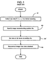
- Fig.1 is a flowchart showing a conventional sequential process for collecting image data based on helical scanning and producing an image from the data.
- Step B1 samples raw data by helical scanning. Specifically, an X-ray tube and associated detector are turned around an object under test, while the object (or alternatively the X-ray tube and detector) is moved straight along an axis, i.e., z axis, and raw data of views at multiple sampling positions on the z axis is sampled.
- an axis i.e., z axis
- raw data of views at multiple sampling positions on the z axis is sampled.
- Step B2 specifies an image reconstructing position So.
- Step B4' samples data of all views at the position So needed for image reconstruction. Specifically, if raw data R(no,io,j) at the position So exists, it is taken in, and furthermore data ro(ix,j) for view number ix other than io is calculated by interpolation from raw data R(nx',ix,j) of a nearby view with a smaller turn number than that of So (will be called "on one side" of So) and raw data R(nx'',ix,j) of another nearby view with a larger turn number than that of So (will be called “on another side” of So).
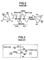
- Fo represent the X-ray trajectories of raw data R(no,io,l), R(no,io,(J+1)/2), and R(no,io,J)
- Fx represent the X-ray trajectories of raw data R(no,ix,l), R(no,ix,(J+1)/2), and R(no,ix,J)
- Step B5 converts the raw data R(no,io,j) and interpolation data ro(ix,j) into projection data, and reconstructs an image at the position So from the projection data.
- the step B4' occasionally calculates the interpolate data ro(ix,j) from raw data R(nt',it',jt') of a nearby confronting view on one side of So and raw data R(nt'',it'',jt'') of another nearby confronting view on another side.
- Fig. 3 explains the positional relation of the slice thickness W1 for the raw data R(nx1',ix,j) on one side, slice thickness W2 for the raw data R(nx1'',ix,j) on another side and slice thickness W0 for the interpolation data ro(ix,j) and the sharp varying plane Pv of X-ray absorption coefficients which is the border between X-ray absorption coefficients ⁇ 0 and ⁇ 1 that are different significantly.
- the X-ray absorption coefficient ⁇ 0 is of bone (with a CT value ranging from 800 to 3000) and ⁇ 1 is of air (with a CT value of about -1000), for example.
- the interpolation data ro(ix,j) must be calculated in consideration of the fact that the raw data R(nx1',ix,j) and R(nx1'',ix,j) are affected by the different X-ray absorption coefficients ⁇ 0 and ⁇ 1.
- the conventional interpolation data calculating scheme is merely based on the weighting in terms of the inverse proportion of the distances between the position So of interpolation data ro(ix,j) and the positions S1 and S2 of nearby raw data R(nx',ix,j) and R(nx'',ix,j), and does not consider the influence of the existence of different X-ray absorption coefficients ⁇ 0 and ⁇ 1, i.e., the influence of partial volume.
- the prior art is deficient in that line-shaped or band-shaped partial volume artifacts are liable to emerge. Partial volume artifacts are pronounced when the labyrinth where bone and air coexist is sliced, for example.
- a first object of the invention is to provide a method of producing interpolation data capable of reducing partial volume artifacts.
- a second object of the invention is to provide a method of inferring the position of a sharp varying plane of X-ray absorption coefficients.
- a third object of the invention is to provide an X-ray CT apparatus capable of carrying out properly the method of producing interpolation data and the method of inferring the position of a sharp varying plane of X-ray absorption coefficients.
- the invention based on a first viewpoint resides in a method of producing interpolation data, the method comprising the steps of collecting data while turning at least one of an X-ray tube and a detector around an object under test and providing a linear movement for the object relative to the X-ray tube and/or detector, evaluating weights which depend on the degree of influence of partial volume on data for the position of interpolation, and producing interpolation data for an image reconstruction plane from the collected data based on the computation of weighted interpolation with the weights.
- the invention based on a second viewpoint resides in the above-mentioned method of producing interpolation data, wherein said method evaluates X-ray attenuation coefficients on both sides of a sharp varying plane of X-ray absorption coefficients from data used for producing interpolation data, calculates a mean X-ray attenuation coefficient by weight-averaging the X-ray attenuation coefficients with said weights, and calculates interpolation data by using the mean X-ray attenuation coefficient.
- the invention based on a third viewpoint resides in a method of inferring the position of a sharp varying plane of X-ray absorption coefficients, the method comprising the steps of collecting data while turning at least one of an X-ray tube and a detector around an object under test and providing a linear movement for the object relative to the X-ray tube and/or detector, calculating the difference of two pieces of data having a same X-ray trajectory and existing on both sides of a plane of concern and adding the differential value to a coordinate-correspondent buffer of respective xy coordinates on the X-ray trajectory, with the operation being repeated for data of multiple views near the plane of concern, storing the accumulative values in the buffers together with the z-axis position of the plane of concern, with the operation being repeated while varying the z-axis position within a prescribed range on the plane of concern, obtaining the distribution along z-axis positions of the accumulative values in the buffers of same xy coordinates, and inferring the z-axi
- the invention based on a fourth viewpoint resides in a method of inferring the position of a sharp varying plane of X-ray absorption coefficients, the method comprising the steps of sampling data at multiple z-axis positions along at least two directions of different angles of an X-ray tube or a detector relative to an object under test, adding the sampled data to coordinate-correspondent buffers of respective xy coordinates on the X-ray trajectories, obtaining the distribution along z-axis positions of the accumulative values in the buffers of same xy coordinates, and inferring the z-axis position of sharp varying plane of X-ray absorption coefficients for the xy coordinates based on the distribution.
- the invention based on a fifth viewpoint resides in a method of inferring the position of a sharp varying plane of X-ray absorption coefficients, the method comprising the steps of sampling data at multiple z-axis positions along a same direction of an X-ray tube or a detector relative to an object under test, storing sampled data of respective detector channels at respective z-axis positions in channel-correspondent buffers of respective detector channels, obtaining the distribution along z-axis positions of the contents of the buffers of a same detector channel, inferring the z-axis position of sharp varying plane of X-ray absorption coefficients for respective detector channels based on the distribution, storing data of the inferred z-axis positions in coordinate-correspondent buffers of respective xy coordinates on the X-ray trajectories, sampling data at the inferred z-axis positions along at least one direction of the X-ray tube or detector different from the first-mentioned angle, adding the sampled data to the coordinate
- the invention based on a sixth viewpoint resides in an X-ray CT apparatus which comprises means for collecting data while turning at least one of an X-ray tube and a detector around an object under test and providing a linear movement for the object relative to the X-ray tube and/or detector, means for calculating weighting factors that depend on the degree of the influence of partial volume on data at the position of interpolation, means for implementing the computation of weighted interpolation with the calculated weighting factors for the data collected by the data collecting means, and means for reconstructing an image on an image reconstruction plane by implementing the image reconstructing computation by using the interpolation data resulting from the interpolation by the interpolation computing means.
- the invention based on a seventh viewpoint resides in the above-mentioned X-ray CT apparatus, wherein the weighting factor calculating means calculates weighting factors based on the relation between the z-axis position of interpolation data, slice thickness and z-axis position of sharp varying plane of X-ray absorption coefficients.
- the invention based on an eighth viewpoint resides in the above-mentioned X-ray CT apparatus, wherein the weighted interpolation computing means calculates X-ray attenuation coefficients on both sides of the sharp varying plane of X-ray absorption coefficients based on data used for producing interpolation data, evaluates a mean X-ray attenuation coefficient by calculating a weighted mean of X-ray attenuation coefficients with the weighting factors, and calculates interpolation data by using the mean X-ray attenuation coefficient.
- interpolation data on an image reconstruction plane is produced from data sampled by helical scanning based on the computation of weighted interpolation with weights that depend on the degree of the influence of partial volume on the interpolation data. Consequently, partial volume artifacts can be reduced.
- interpolation data producing method of the second viewpoint X-ray attenuation coefficients on one and another sides of the position of a sharp varying plane of X-ray absorption coefficients are evaluated from data used for producing interpolation data. Next, a weighted mean of the X-ray attenuation coefficients is calculated by using the above-mentioned weights. Next, interpolation data is calculated by using the mean X-ray attenuation coefficient. In consequence, the method renders the weighting to projection data, as will be explained in detail later, enabling information of smaller X-ray absorption coefficients to contribute significantly to the image.
- the difference of two pieces of data having a same X-ray trajectory and existing on both sides of a plane of concern is calculated and the differential value is accumulated in a coordinate-correspondent buffer of respective xy coordinates, the operation being repeated for data of multiple views near the plane of concern, the accumulative values in the buffers are stored together with the z-axis position of the plane of concern. The operation is repeated while varying the z-axis position within a certain range on the plane of concern.
- the z-axis position of sharp varying plane of X-ray absorption coefficients for the xy coordinates is inferred.
- the differential value is greater if the sharp varying plane of X-ray absorption coefficients is located between two pieces of data. Accordingly, in adding data to coordinate-correspondent buffers, the nearer the plane of concern to the sharp varying plane of X-ray absorption coefficients, the larger is the number of times of addition of larger differential values and thus the larger is value of buffer contents.
- the value of buffer contents is maximum when the plane of concern coincides with the sharp varying plane of X-ray absorption coefficients. Accordingly, based on the distribution of accumulative values along z-axis positions in the coordinate-correspondent buffers for the same xy coordinates, the peak position of distribution can be inferred to be the z-axis position of sharp varying plane of X-ray absorption coefficients.
- data is sampled at multiple z-axis positions along at least two directions of different angles of the X-ray tube or detector relative to the object under test.
- the sampled data is accumulated in coordinate-correspondent buffers of respective xy coordinates on the X-ray trajectory.
- the distribution along z-axis positions of accumulative values in the coordinate-correspondent buffers of the same xy coordinates is obtained, and the z-axis position of sharp varying plane of X-ray absorption coefficients relevant to the xy coordinates is inferred based on the distribution.
- Accumulating data sampled along different directions in the buffers which correspond to coordinates on the X-ray trajectory produces values indicative of the X-ray absorption coefficients at the xy coordinates.
- An accumulative value at a portion with a large X-ray absorption coefficient differ greatly from an accumulative value at a portion with a small X-ray absorption coefficient.
- the sharp-varying position of distribution can be inferred to be the z-axis position of sharp varying plane of X-ray absorption coefficients.
- data of detector channels at z-axis positions is stored in channel-correspondent buffers for respective detector channels.
- the z-axis position of sharp varying plane of X-ray absorption coefficients for each detector channel is inferred based on the distribution along z-axis positions of the channel-correspondent buffers of the same detector channel.
- the data of the inferred z-axis positions is stored in the coordinate-correspondent buffers of respective xy coordinates on the X-ray trajectory
- data on the inferred z-axis position is sampled along at least one direction of the X-ray tube or detector different from the first-mentioned angle
- the sampled data is accumulated in the coordinate-correspondent buffers of respective xy coordinates on the X-ray trajectory.
- the xy-coordinate position of sharp varying plane of X-ray absorption coefficients for the inferred z-axis position is inferred.
- An accumulative value at a portion with a large X-ray absorption coefficient differ greatly from an accumulative value at a portion with a small X-ray absorption coefficient. Accordingly, based on the distribution of accumulative values along z-axis positions in the coordinate-correspondent buffers for the same xy coordinates, the sharp-varying position of the distribution can be inferred to be the z-axis position of sharp varying plane of X-ray absorption coefficients. Next, adding the data obtained in different directions to the buffers which correspond to coordinates on the X-ray trajectory produces values indicative of the X-ray absorption coefficients at the xy coordinates. Accordingly, the xy coordinates of sharp varying plane of X-ray absorption coefficients can be inferred from the accumulative values.
- interpolation data on an image reconstruction plane is produced from data sampled by helical scanning based on the computation of weighted interpolation with weights that depend on the degree of the influence of partial volume on the interpolation data. Consequently, partial volume artifacts can be reduced.
- weighting factors are calculated based on the relation between the z-axis position of interpolation data, slice thickness and z-axis position of sharp varying plane of X-ray absorption coefficients. Consequently, weighting factors which depend on the degree of partial volume can be applied.
- X-ray attenuation coefficients on one and another sides of a sharp varying plane of X-ray absorption coefficients are evaluated based on data used for producing interpolation data.
- a mean X-ray attenuation coefficient is evaluated by calculating a weighted mean of the two X-ray attenuation coefficients based on the weighting factors.
- interpolation data is calculated by using the mean X-ray attenuation coefficient.
- the apparatus renders the weighting to the projection data, as will be explained in detail later, enabling information of smaller X-ray absorption coefficients to contribute significantly to the image.
- the inventive interpolation data producing method is capable of producing interpolation data which is relieved of the influence of partial volume.
- the inventive method of inferring the position of a sharp varying plane of X-ray absorption coefficients is capable of inferring the position of sharp varying plane of X-ray absorption coefficients.
- the inventive X-ray CT apparatus is capable of carrying out properly the method of producing interpolation data and the method of inferring the position of a sharp varying plane of X-ray absorption coefficients.
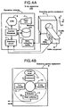
- Figs. 4A and 4B show the X-ray CT apparatus based on the first embodiment of this invention.
- the X-ray CT apparatus 100 consists primarily of an operation console 1, a table equipment 8, and a scanning gantry equipment 9.
- the operation console 1 includes an input unit 2 which receives operator's instructions and information, a central processor 3 which implements the scanning operation, the process of inferring the position of sharp varying plane of X-ray absorption coefficients, the process of producing interpolation data and the process of reconstructing an image, an interface circuit 4 which delivers control commands and signals to the table equipment 8 and scanning gantry equipment 9, a data sampling buffer circuit 5 which stores data sampled by the scanning gantry equipment 9, a CRT display unit 6 which displays images and data, and a memory unit 7 which stores programs and data.
- the table equipment 8 including a slide controller 8a moves a cradle 8c, with an object under test (patient to be scanned) being placed thereon, in the z-axis direction.
- the scanning gantry equipment 9 includes an X-ray controller 10, an X-ray tube 11, an collimator 12, a detector 13, a data collector 14, and a turn controller 15 which turns the X-ray tube 11 and associated devices around the longitudinal axis of the test object.
- the scanning gantry equipment 9 may be moved in the z-axis direction in place of or in addition to the movement of the table equipment 8.
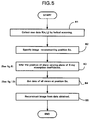
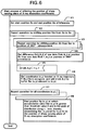
- Fig. 5 shows by flowchart the sequential process of the X-ray controller 10 for collecting data by helical scanning and forming an image.
- Step B1 samples raw data R(n,i,j) by helical scanning. Specifically, with the X-ray tube 11, collimator 12 and detector 13 being operated to turn and the test object (or alternatively the X-ray tube 11, collimator 12 and detector 13) being moved straight along the z-axis, raw data R(n,i,j) of multiple views is sampled at multiple sampling positions on the z-axis. Raw data is expressed in terms of the turn number n for the turning of the devices 11,12 and 13, view number i and detector channel number j, as mentioned previously.
- Step B2 specifies an image reconstructing position So.
- Step B3 infers the position (X,Y,Z) of a sharp varying plane of X-ray absorption coefficients, as will be explained later in connection with Fig. 6.
- Step B4 samples data of all views at the position So needed for image reconstruction. Specifically, if raw data R(no,io,j) of the position So exists, it is taken in, and furthermore data ro(ix,j) for view number ix other than io is calculated by interpolation from raw data R(nx',ix,j) of a nearby view with a smaller turn number than that of So (will be called "on one side" of So) and raw data R(nx'',ix,j) of another nearby view with a larger turn number than that of So (will be called “on another side” of So).
- a weighting factor is calculated based on the relation of the z-axis position where the raw data is sampled, the slice thickness for the raw data and the z-axis position of sharp varying plane of X-ray absorption coefficients, and interpolation data is produced by the computation of interpolation with the weighting factor, as will be explained in detail later in connection with Fig. 12.
- Step B5 converts the raw data R(no,io,j) and interpolation data ro(ix,j) into projection data, and reconstructs the image of the position So from the projection data.
- the step B4 occasionally calculates the interpolate data ro(ix,j) from raw data R(nt',it',jt') of a nearby confronting view on one side of So and raw data R(nt'',it'',jt'') of another nearby confronting view on another side.
- Fig. 6 shows by flowchart of PAD (Program Analysis Diagram) the process of inferring the position of sharp varying plane of X-ray absorption coefficients.
- PAD Program Analysis Diagram
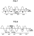
- Step V1 sets a start position Ss and end position Se of the range of inference of the position of sharp varying plane of X-ray absorption coefficients.
- the start position Ss is set to be a z-axis position with a distance of the width equivalent to 360° plus a half the slice thickness W1 on one side of So
- the end position Se is set to be a z-axis position with a distance of the width equivalent to 360° plus a half the slice thickness W2 on another side of So, as shown in Fig. 7.
- the range between Ss and Se may be set much wider.
- the width equivalent to 360° is generally comparable to the slice thickness.
- Step V2 repeats the following step V3 by shifting the pointer Sm of the plane of concern from the start position Ss to the end position Se.
- Step V3 repeats the following step V4 through step V6 by shifting the pointer Sk of difference evaluation from the position Sm to the position of 1-turn advancement.
- Step V4 subtracts raw data R(nk-1,ik,j) of the position of 1-turn precedence from raw data R(nk,ik,j) of the position Sk thereby to evaluate the difference d(nk,ik,j).
- Step V5 tests as to whether the absolute value of difference d(nk,ik,j) is greater than a threshold value ⁇ . If it is greater than ⁇ the sequence proceeds to step V6, or otherwise the sequence returns to step V3.
- the threshold value ⁇ is selected in advance such that the absolute value of difference d(nk,ik,j) is greater than ⁇ when the sharp varying plane of X-ray absorption coefficients exists between the position Sk and the position of 1-turn precedence or the absolute value of difference d(nk,ik,j) is smaller than ⁇ when it does not exist.
- the step V5 may be omitted, it prevents the accumulative value, which will be explained later, from increasing due to the accumulation of noises.
- Step V6 adds the difference d(nk,ik,j) to the coordinate-correspondent buffer Bm(x,y) for the coordinates (x,y) on an X-ray trajectory T(ik,j) that is determined from the view number ik and detector channel number j.
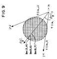
- Fig. 9 shows X-ray trajectories T(ik,l), T(ik,(J+1)/2) and T(ik,J), and coordinate-correspondent buffers Bm(x,y).
- the difference d(nk,ik,(J+1)/2) between raw data R(nk,ik,(J+1)/2) and raw data R(nk-1,ik,(J+1)/2) of the position of 1-turn precedence is greater than the threshold value ⁇ the difference d(nk,ik,(J+1)/2) is added to coordinate-correspondent buffers Bm(3,4), Bm(5,6), Bm(7,8) and so on for coordinates (3,4), (5,6), (7,8) and so on located on the trajectory T(ik,(J+1)/2).
- Fig. 10 shows the sinogram pertinent to coordinates (3,4). Using this sinogram reveals coordinates (x,y) located on an X-ray trajectory T(ik,j).
- the coordinate-correspondent buffers Bm(x,y) contain accumulative values Dm(x,y) of the position Sm. Accumulative values Dm(x,y) are stored together with the position Sm. Since the nearer the position Sm to the sharp varying plane of X-ray absorption coefficients, the larger is the number of times of summation of the difference d(nk,ik,j) and thus the larger is the accumulative value Dm(x,y). The Dm(x,y) takes the maximum value when the position Sm coincides with the sharp varying plane of X-ray absorption coefficients.
- Dm'(x,y) is d1+d2+...+d10
- Dm(x,y) is d2+d3+...+d10+d11
- Dm(x,y) is calculated simply by Dm'(x,y)-d1+d11.
- step V7 repeats the following step V8 for all coordinates (x,y).
- Step V8 finds for each coordinates (x,y) a position Sp among positions Sm at which the accumulative value Dm(x,y) is greater than the threshold value ⁇ and is the peak of distribution along positions Sm. If such position Sp is found, the coordinate (x,y) and position Sp are inferred to be the position of sharp varying plane of X-ray absorption coefficients.
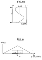
- Fig. 11 shows an example of the distribution of accumulative values Dm(3,4) along position Sm for xy coordinates (3,4).
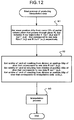
- Fig. 12 shows by flowchart the process of producing interpolation data.
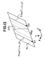
- Step H1 evaluates a mean position ASp of sharp varying plane of X-ray absorption coefficients from a curve CPv of X-ray absorption coefficient sharp varying plane that passes through a plane PL that includes the X-ray trajectories T(nx1',ix,j) and T(nx1'',ix,j) which correspond to the raw data R(nx1',ix,j) and R(nx1'',ix,j), respectively, used for producing the interpolation data ro(ix,j), as shown in Fig. 13.
- the ASp can be obtained as a z coordinate of the bisector of the curve CPv, for example.
- the step H2 evaluates widths b1 and b2 resulting from division of a slice thickness W2, which corresponds to the raw data R(nx1'',ix,j), at the mean position ASp of X-ray absorption coefficient sharp varying plane.
- the step H2 evaluates widths c1 and c2 resulting from division of a slice thickness W0, which corresponds to the interpolation data ro(ix,j), at the mean position ASp of X-ray absorption coefficient sharp varying plane.
- Step H3 implements the computation of interpolation. Specifically, the following simultaneous equations (1) and (2) are solved to evaluate X-ray attenuation coefficients K ⁇ 0 and K ⁇ 1.
- R(nx1',ix,j) (a1/M) exp ⁇ -K ⁇ 0 ⁇ + (a2/M) exp ⁇ -K ⁇ 1 ⁇
- R(nx1'',ix,j) (b1/M) exp ⁇ -K ⁇ 0 ⁇ + (b2/M) exp ⁇ -K ⁇ 1 ⁇
- ro(ix,j) (c1/M) exp ⁇ -K ⁇ 0 ⁇ + (c2/M) exp ⁇ -K ⁇ 1 ⁇
- This interpolation data ro(ix,j) is calculated from the raw data R(nx1',ix,j) and R(nx1'',ix,j) by weighted interpolation with the weighting factors a1/M, a2/M, b1/M, b2/M, c1/M and c1/M evaluated based on the relation of the z-axis position of slicing for the ro, slice thickness and z-axis position of sharp varying plane of X-ray absorption coefficients, and accordingly it comprehends the influence of partial volume appropriately, enabling the suppression of partial volume artifacts.
- the incident X-ray strength at the portion a1 of the slice thickness W1 for the raw data R(nx1',ix,j) is (a1/M)Io and the X-ray absorption coefficient is ⁇ 0, and therefore the transmitting X-ray strength Ia1 is given as follows.
- Ia1 (a1/M) Io ⁇ exp ⁇ - ⁇ 0 (s) ds ⁇
- the incident X-ray strength is (a2/M)Io and the X-ray absorption coefficient is ⁇ 1, and therefore the transmitting X-ray strength Ia2 is given as follows.
- Ia2 (a2/M) Io ⁇ exp ⁇ - ⁇ 1 (s) ds ⁇ Accordingly, the total transmitting X-ray strength Ia detected is given as follows.
- the step H3 of the foregoing first embodiment can be altered to calculate the interpolation data as projection data.
- Pr(ix,j) projection data Pr(ix,j) to be obtained is related to the interpolation data ro(ix,j) as follows.
- Pr(ix,j) ln (ro(ix, j))
- Pr(ix,j) -ln (R(nx1', ix, j)) + ln (a1/M [exp ⁇ K ( ⁇ 0- ⁇ 1) ⁇ ] a2/M -a2/M [exp ⁇ K ( ⁇ 0- ⁇ 1) ⁇ ] -a1/M ) or
- Pr(ix,j) -ln (R(nx1'', ix, j)) + ln (b1/M[exp ⁇ K ( ⁇ 0- ⁇ 1) ⁇ ] b2/M + b2/M[exp ⁇ K ( ⁇ 0- ⁇ 1) ⁇ ] -b1/M )
- ⁇ P can be obtained from the known interpolation data R(nx1',ix,j) and R(nx1'',ix,j), and accordingly exp ⁇ K( ⁇ 0- ⁇ 1) ⁇ can be obtained from the ⁇ P.
- step H3 of the foregoing first embodiment in which the simultaneous equations (1) and (2) are solved, can be altered to evaluate the X-ray attenuation coefficients K ⁇ 0 and K ⁇ 1 in a different manner as follows.
- step H3 of the foregoing first embodiment can be altered to obtain the interpolation data ro(ix,j) based on the following formula, instead of the formula (3).
- ro(ix,j) exp ⁇ - (c1/M) K ⁇ 0 - (c2/M) K ⁇ 1 ⁇
- Calculation of this formula is equivalently the evaluation of a mean X-ray absorption coefficient based on the weight-averaging of the X-ray attenuation coefficients K ⁇ 0 and K ⁇ 1 and the computation of interpolation data ro(ix,j) by use of the resulting mean X-ray absorption coefficient.
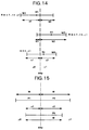
- Fig. 15 shows projection data P1 of a slice with slice thickness M in a portion of X-ray coefficient ⁇ 0, projection data P2 of a slice with slice thickness M in a portion of X-ray absorption coefficient ⁇ 1, and projection data P0 of a slice having thickness c1 in a portion of X-ray absorption coefficient ⁇ 0 and thickness c2 in a portion of X-ray absorption coefficient ⁇ 1.
- the fifth embodiment of this invention is a method of inferring the position of a sharp varying plane of X-ray absorption coefficients without being based on helical scanning.
- Fig. 16 shows by flowchart (PAD) the process of inferring the position of sharp varying plane of X-ray absorption coefficients.
- Step C1 sets a start position Ss and end position Se of the range of inference of the position of sharp varying plane of X-ray absorption coefficients.
- Step C2 repeats the following steps C3 through C6 by shifting the scanning position pointer Sm from the start position Ss to the end position Se.
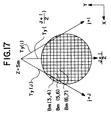
- Step C3 places the X-ray tube 11, collimator 12 and detector 13 at their angular positions so that the X-ray is projected to the xz plane, and samples raw data Ry(Sm,j) at the scanning position Sm.
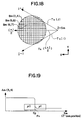
- Step C4 stores the raw data Ry(Sm,j) in the coordinate-correspondent buffer Bm(x,y) relevant to the coordinate (x,y) located on the X-ray trajectory Ty(j) which is determined by the detector channel number j, as shown in Fig. 17.
- Step C5 relocates the X-ray tube 11, collimator 12 and detector 13 so that the X-ray is projected to the yz plane, and samples raw data Rx(Sm,j) at the sampling position Sm.
- Step C6 adds the raw data Rx(Sm,j) to the buffer Bm(x,y) relevant to the coordinate (x,y) located on the X-ray trajectory Tx(j) which is determined by the detector channel number j, as shown in Fig. 18.
- the coordinate-correspondent buffers Bm(x,y) contain accumulative values Am(x,y) of the positions Sm ranging from Ss to Se.
- Step C7 repeats the following step C8 for all coordinates (x,y).
- Step C8 finds for individual coordinates (x,y) a position Sp at which the distribution along the z-axis of the accumulative values Am(x,y) in the buffers Bm(x,y) varies sharply. If such position Sp is found, the coordinate (x,y) and position Sp are inferred to be the position of sharp varying plane of X-ray absorption coefficients.
- Fig. 19 shows an example of the distribution of accumulative values Am(3,4) along positions Sm for xy coordinates (3,4).
- the sixth embodiment of this invention is another method of inferring the position of a sharp varying plane of X-ray absorption coefficients without being based on helical scanning.
- Fig. 20 shows by flowchart the process of inferring the position of sharp varying plane of X-ray absorption coefficients.
- Step F1 sets a start position Ss and end position Se of the range of inference of the position of sharp varying plane of X-ray absorption coefficients.
- Step F2 repeats the following steps F3 and F4 by shifting the scanning position pointer Sm from the start position Ss to the end position Se.
- Step F3 places the X-ray tube 11, collimator 12 and detector 13 at their angular positions so that the X-ray is projected to the xz plane, and samples raw data Ry(Sm,j) at the scanning position Sm.
- Step F4 stores the raw data Ry(Sm,j) in the channel-correspondent buffer Cm(j) relevant to the detector channel number j.
- the channel-correspondent buffers Cm(j) contain raw data Ry(Sm,j) of the positions Sm ranging from Ss to Se.
- Step F5 repeats the following step F6 for all channel numbers j.
- Step F6 finds for individual channel number j a position Sp(j) at which the distribution of raw data Ry(Sm,j) along the z-axis varies sharply.
- position Sp(j) is inferred to be the position of sharp varying plane of X-ray absorption coefficients.
- Step F7 repeats the following steps F8 through F11 by setting the position Sp(j) sequentially in the scanning position counter Sm.
- Step F8 stores the raw data Ry(Sm,j) in the coordinate-correspondent buffer Bm(x,y) relevant to the coordinate (x,y) on the X-ray trajectory Ty(j) which is determined by the detector channel number j.
- Step F9 projects the X-ray onto the yz plane at the scanning position Sm, and samples raw data Rx(Sm,j).
- Step F10 adds the raw data Rx(Sm,j) to the coordinate-correspondent buffer Bm(x,y) relevant to the coordinates (x,y) on the X-ray trajectory Tx(j) which is determined by the detector channel number j.
- Step F11 repeats the following step F12 for all coordinates (x,y).
- Step F12 tests for individual coordinates (x,y) as to whether or not the contents of buffer Bm(x,y) is greater than a threshold value ⁇ . It obtains the profile of the range of values of buffers Bm(x,y) in excess of the threshold value ⁇ , and infers from the coordinates (x,y) of profile and positions Sm that the position (x,y;Sm) is the position of sharp varying plane of X-ray absorption coefficients.
- projection data R(nx',ix,j) and R(nx'',ix,j) of the same view number and same detector channel number as those of interpolation data ro(ix,j) may be used.
Landscapes
- Physics & Mathematics (AREA)
- General Physics & Mathematics (AREA)
- Engineering & Computer Science (AREA)
- Theoretical Computer Science (AREA)
- Apparatus For Radiation Diagnosis (AREA)
Priority Applications (1)
| Application Number | Priority Date | Filing Date | Title |
|---|---|---|---|
| EP96116955A EP0838784A1 (de) | 1996-10-22 | 1996-10-22 | Verfahren zur Verringerung von Artifakten im Tomograph |
Applications Claiming Priority (1)
| Application Number | Priority Date | Filing Date | Title |
|---|---|---|---|
| EP96116955A EP0838784A1 (de) | 1996-10-22 | 1996-10-22 | Verfahren zur Verringerung von Artifakten im Tomograph |
Publications (1)
| Publication Number | Publication Date |
|---|---|
| EP0838784A1 true EP0838784A1 (de) | 1998-04-29 |
Family
ID=8223322
Family Applications (1)
| Application Number | Title | Priority Date | Filing Date |
|---|---|---|---|
| EP96116955A Withdrawn EP0838784A1 (de) | 1996-10-22 | 1996-10-22 | Verfahren zur Verringerung von Artifakten im Tomograph |
Country Status (1)
| Country | Link |
|---|---|
| EP (1) | EP0838784A1 (de) |
Cited By (1)
| Publication number | Priority date | Publication date | Assignee | Title |
|---|---|---|---|---|
| EP1526482A2 (de) | 2003-10-20 | 2005-04-27 | Hitachi, Ltd. | Computertomograph und Methode zur Verringerung des nichtlinearen Teilvolumeneffekts in Computertomographen |
Citations (3)
| Publication number | Priority date | Publication date | Assignee | Title |
|---|---|---|---|---|
| EP0549180A2 (de) * | 1991-12-23 | 1993-06-30 | General Electric Company | Segmentierter Detektor für Abtastgerät in der rechnergestützten Tomographie |
| US5412703A (en) * | 1993-02-04 | 1995-05-02 | Institute For Radiological Image Science, Inc. | Reduced partial volume artifacts in image reconstruction, with application to X-ray computed tomography |
| EP0713678A1 (de) * | 1994-11-25 | 1996-05-29 | Picker International, Inc. | Abbildungsverfahren und entsprechende Vorrichtung |
-
1996
- 1996-10-22 EP EP96116955A patent/EP0838784A1/de not_active Withdrawn
Patent Citations (3)
| Publication number | Priority date | Publication date | Assignee | Title |
|---|---|---|---|---|
| EP0549180A2 (de) * | 1991-12-23 | 1993-06-30 | General Electric Company | Segmentierter Detektor für Abtastgerät in der rechnergestützten Tomographie |
| US5412703A (en) * | 1993-02-04 | 1995-05-02 | Institute For Radiological Image Science, Inc. | Reduced partial volume artifacts in image reconstruction, with application to X-ray computed tomography |
| EP0713678A1 (de) * | 1994-11-25 | 1996-05-29 | Picker International, Inc. | Abbildungsverfahren und entsprechende Vorrichtung |
Non-Patent Citations (2)
| Title |
|---|
| BRESLER Y ET AL: "OPTIMAL INTERPOLATION IN HELICAL SCAN 3D COMPUTERIZED TOMOGRAPHY", MULTIDIMENSIONAL SIGNAL PROCESSING, AUDIO AND ELECTROACOUSTICS, GLASGOW, MAY 23 - 26, 1989, vol. 3, 23 May 1989 (1989-05-23), INSTITUTE OF ELECTRICAL AND ELECTRONICS ENGINEERS, pages 1472 - 1475, XP000089143 * |
| CRAWFORD C R ET AL: "MOVING BEAM HELICAL CT SCANNING", IEEE TRANSACTIONS ON MEDICAL IMAGING, vol. 15, no. 2, 1 April 1996 (1996-04-01), pages 188 - 196, XP000584346 * |
Cited By (3)
| Publication number | Priority date | Publication date | Assignee | Title |
|---|---|---|---|---|
| EP1526482A2 (de) | 2003-10-20 | 2005-04-27 | Hitachi, Ltd. | Computertomograph und Methode zur Verringerung des nichtlinearen Teilvolumeneffekts in Computertomographen |
| EP1526482A3 (de) * | 2003-10-20 | 2005-06-29 | Hitachi, Ltd. | Computertomograph und Methode zur Verringerung des nichtlinearen Teilvolumeneffekts in Computertomographen |
| US7551710B2 (en) | 2003-10-20 | 2009-06-23 | Hitachi, Ltd. | X-ray CT apparatus and X-ray CT imaging method |
Similar Documents
| Publication | Publication Date | Title |
|---|---|---|
| US10045746B2 (en) | Radiation image processing apparatus, method, and medium | |
| US6944264B2 (en) | Method and apparatus for transmitting information about a target object between a prescanner and a CT scanner | |
| US7197172B1 (en) | Decomposition of multi-energy scan projections using multi-step fitting | |
| US7006592B2 (en) | Computed tomography fluoroscopy system | |
| US6292530B1 (en) | Method and apparatus for reconstructing image data acquired by a tomosynthesis x-ray imaging system | |
| US6618466B1 (en) | Apparatus and method for x-ray scatter reduction and correction for fan beam CT and cone beam volume CT | |
| US10219770B2 (en) | Radiographic image processing device, method, and program | |
| EP1475039B1 (de) | Korrektur der Strahlaufhärtung und der mangelnden Gleichförmigkeit der Detektorkanäle in einem Computertomographen mittels eines Phantoms mit länglichem, z.B. elliptischem Querschnitt | |
| US8964933B2 (en) | X-ray computed tomography apparatus, medical image processing apparatus, X-ray computed tomography method, and medical image processing method | |
| US10617378B2 (en) | Radiation image processing device, method, and program configured to eliminate scattered radiation based on a virtual grid characteristic | |
| US10258305B2 (en) | Radiographic image processing device, method, and program | |
| US20110075793A1 (en) | Radiography apparatus | |
| WO1995022115A1 (en) | Reconstruction of images from cone beam data | |
| US7949090B2 (en) | X-ray CT apparatus and image reconstruction method | |
| Herl et al. | Artifact reduction in X-ray computed tomography by multipositional data fusion using local image quality measures | |
| US7280630B2 (en) | Calculation of additional projection data from projection data acquired with a divergent beam | |
| JP3583554B2 (ja) | コーンビームx線断層撮影装置 | |
| US5732117A (en) | Method of producing interpolation data, method of inferring position of sharp varying plane of X-ray absorption coefficients, and x-ray computerized tomography(CT) apparatus | |
| EP1468650B1 (de) | System und Methode zur Röntgencomputertomographie mit Korrektur der Strahlaufhärtung | |
| US5812628A (en) | Methods and apparatus for detecting partial volume image artifacts | |
| US7215734B2 (en) | Method and system for three-dimensional reconstruction of images | |
| KR20050072690A (ko) | 산란 측정 방법, 산란 보정 방법 및 x선 ct 장치 | |
| JPH10225453A (ja) | 計算機式断層写真法システムにおいて基準チャンネルの閉塞を検出する方法及びシステム | |
| EP0838784A1 (de) | Verfahren zur Verringerung von Artifakten im Tomograph | |
| JPH0919426A (ja) | 計算機式断層写真法システム |
Legal Events
| Date | Code | Title | Description |
|---|---|---|---|
| PUAI | Public reference made under article 153(3) epc to a published international application that has entered the european phase |
Free format text: ORIGINAL CODE: 0009012 |
|
| AK | Designated contracting states |
Kind code of ref document: A1 Designated state(s): DE FR GB |
|
| AX | Request for extension of the european patent |
Free format text: AL;LT;LV;RO;SI |
|
| 17P | Request for examination filed |
Effective date: 19980917 |
|
| AKX | Designation fees paid |
Free format text: DE FR GB |
|
| RBV | Designated contracting states (corrected) |
Designated state(s): DE FR GB |
|
| 17Q | First examination report despatched |
Effective date: 20010410 |
|
| STAA | Information on the status of an ep patent application or granted ep patent |
Free format text: STATUS: THE APPLICATION IS DEEMED TO BE WITHDRAWN |
|
| 18D | Application deemed to be withdrawn |
Effective date: 20030501 |