EP0837291B1 - Vapor compression type refrigerating system - Google Patents
Vapor compression type refrigerating system Download PDFInfo
- Publication number
- EP0837291B1 EP0837291B1 EP97114459A EP97114459A EP0837291B1 EP 0837291 B1 EP0837291 B1 EP 0837291B1 EP 97114459 A EP97114459 A EP 97114459A EP 97114459 A EP97114459 A EP 97114459A EP 0837291 B1 EP0837291 B1 EP 0837291B1
- Authority
- EP
- European Patent Office
- Prior art keywords
- pressure
- pressure reducer
- refrigerant
- outlet
- compressor
- Prior art date
- Legal status (The legal status is an assumption and is not a legal conclusion. Google has not performed a legal analysis and makes no representation as to the accuracy of the status listed.)
- Expired - Lifetime
Links
Images













Classifications
-
- F—MECHANICAL ENGINEERING; LIGHTING; HEATING; WEAPONS; BLASTING
- F28—HEAT EXCHANGE IN GENERAL
- F28D—HEAT-EXCHANGE APPARATUS, NOT PROVIDED FOR IN ANOTHER SUBCLASS, IN WHICH THE HEAT-EXCHANGE MEDIA DO NOT COME INTO DIRECT CONTACT
- F28D7/00—Heat-exchange apparatus having stationary tubular conduit assemblies for both heat-exchange media, the media being in contact with different sides of a conduit wall
- F28D7/10—Heat-exchange apparatus having stationary tubular conduit assemblies for both heat-exchange media, the media being in contact with different sides of a conduit wall the conduits being arranged one within the other, e.g. concentrically
- F28D7/106—Heat-exchange apparatus having stationary tubular conduit assemblies for both heat-exchange media, the media being in contact with different sides of a conduit wall the conduits being arranged one within the other, e.g. concentrically consisting of two coaxial conduits or modules of two coaxial conduits
-
- F—MECHANICAL ENGINEERING; LIGHTING; HEATING; WEAPONS; BLASTING
- F25—REFRIGERATION OR COOLING; COMBINED HEATING AND REFRIGERATION SYSTEMS; HEAT PUMP SYSTEMS; MANUFACTURE OR STORAGE OF ICE; LIQUEFACTION SOLIDIFICATION OF GASES
- F25B—REFRIGERATION MACHINES, PLANTS OR SYSTEMS; COMBINED HEATING AND REFRIGERATION SYSTEMS; HEAT PUMP SYSTEMS
- F25B40/00—Subcoolers, desuperheaters or superheaters
-
- F—MECHANICAL ENGINEERING; LIGHTING; HEATING; WEAPONS; BLASTING
- F25—REFRIGERATION OR COOLING; COMBINED HEATING AND REFRIGERATION SYSTEMS; HEAT PUMP SYSTEMS; MANUFACTURE OR STORAGE OF ICE; LIQUEFACTION SOLIDIFICATION OF GASES
- F25B—REFRIGERATION MACHINES, PLANTS OR SYSTEMS; COMBINED HEATING AND REFRIGERATION SYSTEMS; HEAT PUMP SYSTEMS
- F25B41/00—Fluid-circulation arrangements
- F25B41/30—Expansion means; Dispositions thereof
- F25B41/31—Expansion valves
- F25B41/33—Expansion valves with the valve member being actuated by the fluid pressure, e.g. by the pressure of the refrigerant
- F25B41/335—Expansion valves with the valve member being actuated by the fluid pressure, e.g. by the pressure of the refrigerant via diaphragms
-
- F—MECHANICAL ENGINEERING; LIGHTING; HEATING; WEAPONS; BLASTING
- F25—REFRIGERATION OR COOLING; COMBINED HEATING AND REFRIGERATION SYSTEMS; HEAT PUMP SYSTEMS; MANUFACTURE OR STORAGE OF ICE; LIQUEFACTION SOLIDIFICATION OF GASES
- F25B—REFRIGERATION MACHINES, PLANTS OR SYSTEMS; COMBINED HEATING AND REFRIGERATION SYSTEMS; HEAT PUMP SYSTEMS
- F25B41/00—Fluid-circulation arrangements
- F25B41/30—Expansion means; Dispositions thereof
- F25B41/31—Expansion valves
- F25B41/34—Expansion valves with the valve member being actuated by electric means, e.g. by piezoelectric actuators
- F25B41/35—Expansion valves with the valve member being actuated by electric means, e.g. by piezoelectric actuators by rotary motors, e.g. by stepping motors
-
- F—MECHANICAL ENGINEERING; LIGHTING; HEATING; WEAPONS; BLASTING
- F25—REFRIGERATION OR COOLING; COMBINED HEATING AND REFRIGERATION SYSTEMS; HEAT PUMP SYSTEMS; MANUFACTURE OR STORAGE OF ICE; LIQUEFACTION SOLIDIFICATION OF GASES
- F25B—REFRIGERATION MACHINES, PLANTS OR SYSTEMS; COMBINED HEATING AND REFRIGERATION SYSTEMS; HEAT PUMP SYSTEMS
- F25B41/00—Fluid-circulation arrangements
- F25B41/30—Expansion means; Dispositions thereof
- F25B41/39—Dispositions with two or more expansion means arranged in series, i.e. multi-stage expansion, on a refrigerant line leading to the same evaporator
-
- F—MECHANICAL ENGINEERING; LIGHTING; HEATING; WEAPONS; BLASTING
- F25—REFRIGERATION OR COOLING; COMBINED HEATING AND REFRIGERATION SYSTEMS; HEAT PUMP SYSTEMS; MANUFACTURE OR STORAGE OF ICE; LIQUEFACTION SOLIDIFICATION OF GASES
- F25B—REFRIGERATION MACHINES, PLANTS OR SYSTEMS; COMBINED HEATING AND REFRIGERATION SYSTEMS; HEAT PUMP SYSTEMS
- F25B9/00—Compression machines, plants or systems, in which the refrigerant is air or other gas of low boiling point
- F25B9/002—Compression machines, plants or systems, in which the refrigerant is air or other gas of low boiling point characterised by the refrigerant
- F25B9/008—Compression machines, plants or systems, in which the refrigerant is air or other gas of low boiling point characterised by the refrigerant the refrigerant being carbon dioxide
-
- F—MECHANICAL ENGINEERING; LIGHTING; HEATING; WEAPONS; BLASTING
- F25—REFRIGERATION OR COOLING; COMBINED HEATING AND REFRIGERATION SYSTEMS; HEAT PUMP SYSTEMS; MANUFACTURE OR STORAGE OF ICE; LIQUEFACTION SOLIDIFICATION OF GASES
- F25B—REFRIGERATION MACHINES, PLANTS OR SYSTEMS; COMBINED HEATING AND REFRIGERATION SYSTEMS; HEAT PUMP SYSTEMS
- F25B2309/00—Gas cycle refrigeration machines
- F25B2309/06—Compression machines, plants or systems characterised by the refrigerant being carbon dioxide
- F25B2309/061—Compression machines, plants or systems characterised by the refrigerant being carbon dioxide with cycle highest pressure above the supercritical pressure
-
- F—MECHANICAL ENGINEERING; LIGHTING; HEATING; WEAPONS; BLASTING
- F25—REFRIGERATION OR COOLING; COMBINED HEATING AND REFRIGERATION SYSTEMS; HEAT PUMP SYSTEMS; MANUFACTURE OR STORAGE OF ICE; LIQUEFACTION SOLIDIFICATION OF GASES
- F25B—REFRIGERATION MACHINES, PLANTS OR SYSTEMS; COMBINED HEATING AND REFRIGERATION SYSTEMS; HEAT PUMP SYSTEMS
- F25B2341/00—Details of ejectors not being used as compression device; Details of flow restrictors or expansion valves
- F25B2341/06—Details of flow restrictors or expansion valves
- F25B2341/063—Feed forward expansion valves
-
- F—MECHANICAL ENGINEERING; LIGHTING; HEATING; WEAPONS; BLASTING
- F25—REFRIGERATION OR COOLING; COMBINED HEATING AND REFRIGERATION SYSTEMS; HEAT PUMP SYSTEMS; MANUFACTURE OR STORAGE OF ICE; LIQUEFACTION SOLIDIFICATION OF GASES
- F25B—REFRIGERATION MACHINES, PLANTS OR SYSTEMS; COMBINED HEATING AND REFRIGERATION SYSTEMS; HEAT PUMP SYSTEMS
- F25B2400/00—Component parts or details not otherwise provided for in this subclass
- F25B2400/13—Economisers
-
- F—MECHANICAL ENGINEERING; LIGHTING; HEATING; WEAPONS; BLASTING
- F25—REFRIGERATION OR COOLING; COMBINED HEATING AND REFRIGERATION SYSTEMS; HEAT PUMP SYSTEMS; MANUFACTURE OR STORAGE OF ICE; LIQUEFACTION SOLIDIFICATION OF GASES
- F25B—REFRIGERATION MACHINES, PLANTS OR SYSTEMS; COMBINED HEATING AND REFRIGERATION SYSTEMS; HEAT PUMP SYSTEMS
- F25B2600/00—Control issues
- F25B2600/05—Refrigerant levels
-
- F—MECHANICAL ENGINEERING; LIGHTING; HEATING; WEAPONS; BLASTING
- F25—REFRIGERATION OR COOLING; COMBINED HEATING AND REFRIGERATION SYSTEMS; HEAT PUMP SYSTEMS; MANUFACTURE OR STORAGE OF ICE; LIQUEFACTION SOLIDIFICATION OF GASES
- F25B—REFRIGERATION MACHINES, PLANTS OR SYSTEMS; COMBINED HEATING AND REFRIGERATION SYSTEMS; HEAT PUMP SYSTEMS
- F25B2600/00—Control issues
- F25B2600/17—Control issues by controlling the pressure of the condenser
-
- F—MECHANICAL ENGINEERING; LIGHTING; HEATING; WEAPONS; BLASTING
- F25—REFRIGERATION OR COOLING; COMBINED HEATING AND REFRIGERATION SYSTEMS; HEAT PUMP SYSTEMS; MANUFACTURE OR STORAGE OF ICE; LIQUEFACTION SOLIDIFICATION OF GASES
- F25B—REFRIGERATION MACHINES, PLANTS OR SYSTEMS; COMBINED HEATING AND REFRIGERATION SYSTEMS; HEAT PUMP SYSTEMS
- F25B2700/00—Sensing or detecting of parameters; Sensors therefor
- F25B2700/19—Pressures
- F25B2700/193—Pressures of the compressor
- F25B2700/1931—Discharge pressures
-
- F—MECHANICAL ENGINEERING; LIGHTING; HEATING; WEAPONS; BLASTING
- F25—REFRIGERATION OR COOLING; COMBINED HEATING AND REFRIGERATION SYSTEMS; HEAT PUMP SYSTEMS; MANUFACTURE OR STORAGE OF ICE; LIQUEFACTION SOLIDIFICATION OF GASES
- F25B—REFRIGERATION MACHINES, PLANTS OR SYSTEMS; COMBINED HEATING AND REFRIGERATION SYSTEMS; HEAT PUMP SYSTEMS
- F25B2700/00—Sensing or detecting of parameters; Sensors therefor
- F25B2700/19—Pressures
- F25B2700/193—Pressures of the compressor
- F25B2700/1933—Suction pressures
-
- F—MECHANICAL ENGINEERING; LIGHTING; HEATING; WEAPONS; BLASTING
- F25—REFRIGERATION OR COOLING; COMBINED HEATING AND REFRIGERATION SYSTEMS; HEAT PUMP SYSTEMS; MANUFACTURE OR STORAGE OF ICE; LIQUEFACTION SOLIDIFICATION OF GASES
- F25B—REFRIGERATION MACHINES, PLANTS OR SYSTEMS; COMBINED HEATING AND REFRIGERATION SYSTEMS; HEAT PUMP SYSTEMS
- F25B2700/00—Sensing or detecting of parameters; Sensors therefor
- F25B2700/21—Temperatures
- F25B2700/2101—Temperatures in a bypass
-
- F—MECHANICAL ENGINEERING; LIGHTING; HEATING; WEAPONS; BLASTING
- F25—REFRIGERATION OR COOLING; COMBINED HEATING AND REFRIGERATION SYSTEMS; HEAT PUMP SYSTEMS; MANUFACTURE OR STORAGE OF ICE; LIQUEFACTION SOLIDIFICATION OF GASES
- F25B—REFRIGERATION MACHINES, PLANTS OR SYSTEMS; COMBINED HEATING AND REFRIGERATION SYSTEMS; HEAT PUMP SYSTEMS
- F25B2700/00—Sensing or detecting of parameters; Sensors therefor
- F25B2700/21—Temperatures
- F25B2700/2102—Temperatures at the outlet of the gas cooler
-
- F—MECHANICAL ENGINEERING; LIGHTING; HEATING; WEAPONS; BLASTING
- F25—REFRIGERATION OR COOLING; COMBINED HEATING AND REFRIGERATION SYSTEMS; HEAT PUMP SYSTEMS; MANUFACTURE OR STORAGE OF ICE; LIQUEFACTION SOLIDIFICATION OF GASES
- F25B—REFRIGERATION MACHINES, PLANTS OR SYSTEMS; COMBINED HEATING AND REFRIGERATION SYSTEMS; HEAT PUMP SYSTEMS
- F25B2700/00—Sensing or detecting of parameters; Sensors therefor
- F25B2700/21—Temperatures
- F25B2700/2104—Temperatures of an indoor room or compartment
-
- F—MECHANICAL ENGINEERING; LIGHTING; HEATING; WEAPONS; BLASTING
- F25—REFRIGERATION OR COOLING; COMBINED HEATING AND REFRIGERATION SYSTEMS; HEAT PUMP SYSTEMS; MANUFACTURE OR STORAGE OF ICE; LIQUEFACTION SOLIDIFICATION OF GASES
- F25B—REFRIGERATION MACHINES, PLANTS OR SYSTEMS; COMBINED HEATING AND REFRIGERATION SYSTEMS; HEAT PUMP SYSTEMS
- F25B2700/00—Sensing or detecting of parameters; Sensors therefor
- F25B2700/21—Temperatures
- F25B2700/2106—Temperatures of fresh outdoor air
-
- F—MECHANICAL ENGINEERING; LIGHTING; HEATING; WEAPONS; BLASTING
- F25—REFRIGERATION OR COOLING; COMBINED HEATING AND REFRIGERATION SYSTEMS; HEAT PUMP SYSTEMS; MANUFACTURE OR STORAGE OF ICE; LIQUEFACTION SOLIDIFICATION OF GASES
- F25B—REFRIGERATION MACHINES, PLANTS OR SYSTEMS; COMBINED HEATING AND REFRIGERATION SYSTEMS; HEAT PUMP SYSTEMS
- F25B2700/00—Sensing or detecting of parameters; Sensors therefor
- F25B2700/21—Temperatures
- F25B2700/2117—Temperatures of an evaporator
- F25B2700/21171—Temperatures of an evaporator of the fluid cooled by the evaporator
- F25B2700/21173—Temperatures of an evaporator of the fluid cooled by the evaporator at the outlet
-
- F—MECHANICAL ENGINEERING; LIGHTING; HEATING; WEAPONS; BLASTING
- F25—REFRIGERATION OR COOLING; COMBINED HEATING AND REFRIGERATION SYSTEMS; HEAT PUMP SYSTEMS; MANUFACTURE OR STORAGE OF ICE; LIQUEFACTION SOLIDIFICATION OF GASES
- F25B—REFRIGERATION MACHINES, PLANTS OR SYSTEMS; COMBINED HEATING AND REFRIGERATION SYSTEMS; HEAT PUMP SYSTEMS
- F25B2700/00—Sensing or detecting of parameters; Sensors therefor
- F25B2700/21—Temperatures
- F25B2700/2117—Temperatures of an evaporator
- F25B2700/21175—Temperatures of an evaporator of the refrigerant at the outlet of the evaporator
-
- Y—GENERAL TAGGING OF NEW TECHNOLOGICAL DEVELOPMENTS; GENERAL TAGGING OF CROSS-SECTIONAL TECHNOLOGIES SPANNING OVER SEVERAL SECTIONS OF THE IPC; TECHNICAL SUBJECTS COVERED BY FORMER USPC CROSS-REFERENCE ART COLLECTIONS [XRACs] AND DIGESTS
- Y02—TECHNOLOGIES OR APPLICATIONS FOR MITIGATION OR ADAPTATION AGAINST CLIMATE CHANGE
- Y02B—CLIMATE CHANGE MITIGATION TECHNOLOGIES RELATED TO BUILDINGS, e.g. HOUSING, HOUSE APPLIANCES OR RELATED END-USER APPLICATIONS
- Y02B30/00—Energy efficient heating, ventilation or air conditioning [HVAC]
- Y02B30/70—Efficient control or regulation technologies, e.g. for control of refrigerant flow, motor or heating
-
- Y—GENERAL TAGGING OF NEW TECHNOLOGICAL DEVELOPMENTS; GENERAL TAGGING OF CROSS-SECTIONAL TECHNOLOGIES SPANNING OVER SEVERAL SECTIONS OF THE IPC; TECHNICAL SUBJECTS COVERED BY FORMER USPC CROSS-REFERENCE ART COLLECTIONS [XRACs] AND DIGESTS
- Y10—TECHNICAL SUBJECTS COVERED BY FORMER USPC
- Y10S—TECHNICAL SUBJECTS COVERED BY FORMER USPC CROSS-REFERENCE ART COLLECTIONS [XRACs] AND DIGESTS
- Y10S62/00—Refrigeration
- Y10S62/17—Condenser pressure control
Definitions
- the present invention relates to a refrigerating system of a vapor compression type according to the preamble of claim 1 and is suitable for a refrigerating system where a cooling medium, such as a carbon dioxide (CO 2 ) is used in a super critical state.
- a cooling medium such as a carbon dioxide (CO 2 ) is used in a super critical state.
- a refrigerating system according to the preamble of claim 1 is known from WO-A-90 07683.
- CO 2 refrigerating system It has, recently, been strictly required that a refrigerant other than a fluorocarbon (flon) be used in a refrigerating system.
- a vapor compression type refrigerating system has been proposed in which carbon dioxide (CO 2 ) is used as a refrigerant in order to execute a refrigerating cycle. See, for example, Japanese Examined Patent Publication (Kokoku) No. 7-18602. This type of a refrigerating system is referred to below as a CO 2 refrigerating system.
- This CO 2 refrigerating system operates, basically, in the same manner that a conventional refrigerating system, using flon as a refrigerant does.
- the CO 2 refrigerating system is defective in that a pressure at the outlet of the heat emitter is increased to a value as much as 10 times of that in the conventional refrigerating system using flon when a refrigerating capacity is high due to an increased outside air temperature such as that in a summer season.
- Such an increase in the pressure at the outlet of the heat emitter means that the strength of parts constructing the compressor must be correspondingly increased over those in the conventional refrigerating system using flon, resulting in an increase in the size of the system.
- the pressure and the temperature of the CO 2 at the outlet of the heat emitter are controlled along a so-called optimum control line, which makes the coefficient of performance of the system attain the maximum value.
- the coefficient of performance is calculated as a ratio of the change in an enthalpy at the evaporator to compression work at the compressor.
- the pressure reducer is controlled in such a manner that the pressure at the outlet of the heat emitter is varied in accordance with the temperature of the CO 2 at the outlet of the heat emitter.
- a control may cause the degree of super-heating of the refrigerant to be insufficient at the outlet of the evaporator, which may cause a liquid state refrigerant to be sucked by the compressor, thereby damaging the compressor.
- a first object of the present invention is to provide a vapor compression type refrigerating system where is pressure of the refrigerant at the heat emitter larger than critical pressure, capable of preventing the size of the system from being increased while keeping a desired refrigerating capacity.
- a second object of the present invention is to provide a vapor compression type refrigerating system capable of obtaining a desired refrigerating capacity even in a condition such as a cool-down where a thermal load is high.
- a third object of the present invention is to provide a vapor compression type refrigerating system, capable of maintaining an increased efficiency during the execution of the refrigerating system while preventing the compressor from being damaged.
- the refrigerant issuing from the heat emitter is divided into a first flow to a first pressure reducer and to an evaporator and a second flow to a second pressure reducer for gas injection to the compressor, and a heat exchange is generated between the first and second flows of the refrigerant.
- the first flow to the first pressure reducer and the evaporator is cooled by the second flow for injection.
- the above method allows the specific enthalpy of the refrigerant at the inlet of the first pressure reducer to be reduced without increasing the pressure of the refrigerant at the outlet of the heat emitter.
- a difference in the specific enthalpy between the inlet and outlet of the evaporator is increased.
- a minimum operating pressure during the execution of the refrigerating cycle is decreased while keeping a desired refrigerating capacity, thereby preventing the size of the system from being increased. In other words, a small size of parts for constructing the compression system is obtained.
- the second flow of the refrigerant is introduced or injected into the compressor.
- the injected second flow of the refrigerant causes the temperature (specific enthalpy) of the refrigerant to be decreased in the compressor.
- the condition of the refrigerant is determined by an isentropic line at reduced temperature.
- the isentropic line has an increased gradient over the isentropic line prior to the injection.
- a means is preferably provided for varying a cooling performance at the cooler by controlling a degree of the opening of the second pressure reducer.
- control of the second pressure reducer allows the specific enthalpy of the refrigerant to be controlled at the inlet of the evaporator.
- a control of the refrigerating capacity of the system is executed without controlling an operating condition of the compressor.
- control of the cooling capacity by the cooling means is such that the degree of an opening of the second pressure reducer is increased when it is determined that an increase in the cooling ability is necessary and that the degree of an opening of the second pressure reducer is reduced when it is determined that a decrease in the cooling ability is necessary.
- adjustment of the degree of the opening of the first pressure reducer is such that the pressure of the refrigerant at the outlet of the heat emitter is controlled to a predetermined target value which is determined in accordance with the temperature of the refrigerant at the outlet of the heat emitter.
- carbon dioxide is used for the refrigerant.
- the ratio of the pressure difference ⁇ P s between the pressure P i of the refrigerant introduced, after being subjected to a pressure reduction by the first pressure reducing means, into said location of the compressor where the refrigerant is partly compressed and a pressure P s of the refrigerant sucked from the evaporator into the compressor, to the pressure difference ⁇ P d between the pressure P d of the refrigerant discharged from the compressor and a pressure P i of the refrigerant introduced, after subjected to a pressure reduction by the first pressure reducing means into said location of the compressor where the refrigerant is partly compressed is in a range between 0.6 to 0.9.
- the degree of the opening of said pressure reducer is, first, controlled in such a manner that a ratio of the refrigerating capacity at the evaporator to the compression work at the compressor is increased when a thermal load at the evaporator is smaller than a predetermined value.
- the degree of the opening of said pressure reducer is, second, controlled in such a manner that a degree of the opening of the pressure reducer is reduced in accordance with the increase in the thermal load when a thermal load at the evaporator exceeds said predetermined value.
- the vapor compression type refrigerating cycle is executed while maintaining an increased coefficient of a performance when the thermal load is smaller than a predetermined value.
- a commencement of a rapid cooling operation is detected by the thermal load of the evaporator exceeding the predetermined value.
- the degree of the opening of the pressure reducer is reduced in accordance with the increase in the thermal load of the evaporator, thereby obtaining a desired refrigerating capacity even at an increased thermal load condition during the execution of the rapid cooling mode.
- a variation of the pressure as discharged from the compressor is small compared to a vapor compression type refrigerating system where the refrigerant such as CO 2 is operated at a pressure higher than the critical pressure.
- a control of a refrigerating capacity is done by controlling a mass flow amount of the refrigerant recirculated in the system.
- the refrigerating capacity is determined only by the maximum mass flow amount.
- a determination of the compression capacity only by the maximum mass flow amount causes the size of the compressor to be increased.
- a control of the refrigerating capacity is done mainly by controlling the pressure at the outlet of the heat emitter.
- the capacity of the compressor can be determined based on the mass flow amount of the refrigerant when the thermal load to the evaporator is low, i.e., the system is under a steady state.
- the size of the compressor is prevented from being increased.
- said first controlling means controls the degree of the opening of the pressure reducer so that the pressure of the refrigerant at the heat emitter is controlled to a first target value which is determined in accordance with a temperature of the refrigerant at the outlet of the heat emitter
- said second controlling means controls the degree of the opening of the pressure reducer so that the pressure of the refrigerant at the heat emitter is controlled to a second target value which is determined in accordance with a value of the thermal load and the temperature of the refrigerant at the outlet of the heat emitter.
- control of the pressure reducer is done such that a pressure difference between the outlet of the heat emitter and the inlet of the evaporator is equal to a target pressure difference determined in accordance with the temperature of the refrigerant at the outlet of the heat emitter.
- the pressure of the refrigerant at the outlet of the heat emitter is increased or decreased in accordance with the increase or decrease of the thermal load.
- the pressure of the refrigerant at the outlet of the heat emitter is increased, thereby increasing the refrigerating capacity.
- the pressure difference is controlled to a target value which is determined in accordance with the temperature of the refrigerant at the outlet of the heat emitter, which allows the refrigerating cycle to be executed at an increased efficiency.
- carbon dioxide is used as the refrigerant.
- a series of a first and a second pressure reducer is provided.
- the first pressure reducer is for reducing the pressure of the refrigerant from the heat emitter, the first pressure reducer being for controlling the pressure at the outlet of the heat emitter in accordance with the temperature of the refrigerant at the outlet of the heat emitter.
- the second pressure reducer is for reducing the pressure from the separating means, the second pressure reducer being for controlling the flow amount of the refrigerant in such a manner that a degree of a super heat at the inlet of the compressor is controlled to a predetermined value.
- a separator for phase separation of the liquid phase and the gaseous phase of the refrigerant is provided, which is arranged between the first and second pressure reducer.
- the second pressure reducer allows the degree of super heating to be maintained to a predetermined value at the inlet of the compressor, thereby preventing a liquid phase of the refrigerant from being sucked to the compressor, which would otherwise cause the compressor to be damaged.
- the degree of super heating at the inlet of the compressor is controlled to a predetermined value, which would otherwise necessitate an accumulator at the outlet of the evaporator for phase separation of the gaseous phase from the liquid phase. Due to the elimination of the accumulator, a lubricant included in the refrigerant is prevented from being stored in the accumulator. In other words, the lubricant, which is of a reduced flowability is entrained by a high speed flow of gaseous refrigerant sucked into the compressor, which allows a large amount of the lubricant to be fed to the compressor.
- a sufficient amount of lubricant is fed to the compressor, thereby, on one hand, preventing the compressor from seizing and, on the other hand allowing the refrigerating system to be operated at an increased efficiency.
- a third pressure reducer for reducing the pressure of the second flow of the refrigerant
- a cooling means for obtaining a heat exchange between the first flow of the refrigerant directed to the first pressure reducer and the second flow after being subjected to a pressure reduction by the third pressure reducer, thereby cooling the first flow of the refrigerant.
- the refrigerant issued from the heat emitter is subjected to the cooling by the cooler, which allows a specific enthalpy to be reduced at the inlet of the first pressure reducer, thereby increasing a difference in the specific enthalpy between the inlet and outlet of the evaporator.
- an increase in the refrigerating capacity of the vapor compression type refrigerating system is obtained.
- said cooling means is integrated with at least one of the first, second and third pressure reducers.
- said cooling means is integrated with at least one of the first, second and third pressure reducers.
- a conduit is provided for introducing, into the compressor, a gaseous phase of the refrigerant separated at the separating means at a pressure between a pressure inside the heat emitter and a pressure at the evaporator. Due to this construction, a liquid phase of the refrigerant separated from the separating means and at a pressure intermediate between the heat emitter and the pressure at the evaporator is introduced into the compressor. As a result, a liquid phase of refrigerant having an enthalpy lower than that of a saturated liquid introduced into the second pressure reducer, which allows the enthalpy difference to be increased between the inlet and the outlet of the evaporator. Furthermore, an introduction of a gaseous phase of the refrigerant at an intermediate pressure is introduced into the compressor, thereby reducing the compression work at the compressor.
- an increase in an enthalpy difference is obtained between the inlet and the outlet of the evaporator, while reducing a compression work at the compressor and increasing a coefficient of performance of the refrigerating cycle using CO 2 .
- carbon dioxide may also be used.
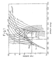
- Fig. 1 is a Mollier chart illustrating an operation of the refrigerating system using CO 2 as a refrigerant.
- a compressor compression of the refrigerant (CO 2 ) of a gaseous state is done, so that a change of a state from a point A to a point B occurs.
- the CO 2 gas is under a condition of a high temperature and a high pressure, i.e., is in a super critical condition.
- the compressed refrigerant from the compressor 1 is subjected to a cooling at the heater (gas cooler), so that a state change between a point B to a point C is obtained.
- the CO 2 is in a gas-liquid combined state.
- the gas-liquid combined state refrigerant is subjected to an evaporation, so that a state change between the points D and A occurs.
- a heat corresponding a latent heat of evaporation is removed from the outside air contacting the evaporator, thereby cooling the outside air.
- a gas-liquid combined stage is obtained when the pressure is lowered below the saturated liquid pressure, i.e., the pressure at the crossing point between the line CD and the saturated liquid line SL.
- the super critical condition refers a condition of the CO 2 , where, irrespective of density of the CO 2 which is roughly equal to the density at a liquid state, particles of CO 2 move as they do in the gaseous state.
- carbon dioxide has a critical temperature of about 31°C, which is lower than that of a flon such as HFC-134a at 101°C, so that it may be possible that the temperature at the outlet of the heat emitter is larger than the critical temperature of CO 2 , which prevents the latter being condensed at the outlet of the heat emitter This means that the line BC in Fig. 1 is prevented from crossing the saturating line SL.
- the state at the outlet of the heat emitter i.e., the point C in Fig. 1 is determined by the discharging pressure of the compressor as well as the temperature of the CO 2 at the outlet of the heat emitter.
- the temperature of the CO 2 at the outlet of the heat emitter is determining by the heat emission capacity at the heat emitter as well as the atmospheric air temperature. It is certain that a control the atmospheric air temperature is impossible, and therefore a control of the condition at the outlet of the heat emitter by means of the temperature of the CO 2 at the outlet of the heat emitter is substantially impossible.
- a control of the state at the outlet of the heat emitter i.e., the state of the point C in Fig. 1 is only done by controlling the discharging pressure of the compressor, i.e., the pressure at the outlet of the heat emitter. Namely, during a condition of an increased atmospheric air temperature, i.e., an increased thermal load as in the summer season, a refrigerating cycle as illustrated by E-F-G-H in Fig. 1 is executed, so as to obtain an increased pressure at the outlet of the heat emitter.
- flon has a lower critical pressured.
- HFC-134a has a critical pressure of 4.07 MPa.
- the maximum pressure during the execution of the refrigerating cycle does not exceed the critical pressure of the flon.
- the pressure at the outlet of the heat emitter in order to increase a refrigerating capacity during a condition of an increased outside atmospheric air temperature (thermal load) condition as occurred during a summer season, the pressure at the outlet of the heat emitter must be as large as about 10 times of the maximum pressure in the refrigerating system using flon.
- Such a highly increased pressure in the refrigerating system using CO 2 necessitates the strength of various parts constructing the system to be larger than that of the conventional system. This is the reason why size of the refrigerating system using CO 2 is larger than that using the flon.
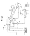
- Fig. 2 generally and schematically illustrates, as a first example, an air conditioning apparatus for a vehicle provided with a CO 2 refrigerating system where a refrigerating cycle is executed while using the carbon dioxide as a refrigerant.
- the refrigerating system is includes a compressor 1, a heat emitter 2, a main pressure reducer 3, an additional pressure reducer 4, a cooler 5, an evaporator 7 and an accumulator 8.
- the heat emitter 2, the cooler 5, the pressure reducer 3, the evaporator 7 and the accumulator 8 are located on a main recirculating conduit 27.
- the compressor 1 is kinematically connected with a rotating movement source such as a crankshaft of an internal combustion engine.
- an electromagnetic clutch is provided for a selective transmission of the rotating movement to the compressor 1.
- an engagement of the clutch causes a rotating movement from the engine to be transmitted to the compressor 1, so that a refrigerant issued from an evaporator 7 is sucked into the compressor 1 and the sucked refrigerant is compressed in the compressor 1.
- a type as disclosed in the Japanese Unexamined Patent Publication (Kokai) No. 61-79947 or Japanese Unexamined Patent Publication (Kokai) No. 63-243481 can be employed, where a two stage compression is done in one and the same compressor.
- the heat emitter or gas cooler 2 is arranged downstream from the compressor 1, and is for executing a heat exchange between the CO 2 as compressed at the compressor 1 and an outside air, so that the refrigerant is cooled, i.e., the heat of the refrigerant is emitted to the atmosphere.
- a branch point 27-1 is arranged at the outlet of the heat emitter 2, so that, from the main recirculating passageway 27 for the refrigerant, a branched passageway 28 is branched, so that a flow of the refrigerant (CO 2 ) from the heat emitter 2 is divided into a first flow in the main passageway 27 and a second flow of the refrigerant (CO 2 ) in the sub passageway 28.
- the sub pressure reducer 4 is arranged in the branch passageway 28, so that the pressure of the CO 2 is reduced to a predetermined value P 1 .
- a cooler 5 is arranged, so that a heat exchange occurres between the first flow of CO 2 of a high temperature in the main passageway 27 and the second flow of the CO 2 of a low temperature from the pressure reducer 4 in the sub passageway 28.
- the first flow in the main passageway 27 is cooled by the second flow of CO 2 at a low temperature in the branched passageway 28 after passed through the sub pressure reducer 4.
- the first flow of the CO 2 in the main passageway 27 is referred herein as a "refrigerating CO 2 ".
- the second flow of the CO 2 in the sub-passageway 28 is referred herein as an "injecting CO 2 ".
- the heat exchange of the injecting CO 2 with respect to the refrigerating CO 2 causes the temperature of the injecting CO 2 in the sub-passageway 27 to be increased.
- the flow of the refrigerant (injecting CO 2 ) of an increased temperature is via the sub-passageway 28 introduced into the compressor 1 and is subjected to a second stage compression at the compressor 1 as well known by those skilled in this art.
- the main pressure reducer 3 is arranged in the main passageway 27 at a location downstream from the heat exchanger 5.
- the main pressure reducer 3 functions to reduce the pressure of the refrigerant to a predetermined value P 2 , which is lower than the predetermined value P 1 at the passageway 28. After the pressure reduction at the pressure reducer 3, the refrigerant is returned to the compressor 1 for a repetition of a cycle.
- the degree of opening of the first pressure reducer 4 is controlled by the controller 10.
- the controller 10 functions as a capacity control means for controlling a cooling performance of the refrigerating CO 2 at the cooler 5 by controlling the degree of the opening of the pressure reducer 4.
- an increase in the degree of the opening of the pressure reducer 4 causes a temperature difference to be reduced between the injecting CO 2 after being subjected to a pressure reduction and the refrigerating CO 2 prior to the pressure reduction, i.e., a temperature difference between the gases to be subjected to the heat exchange at the heat exchanger 5.
- cooling capacity heat exchange capacity
- a reduction in the degree of the opening of the pressure reducer 4 causes a temperature difference to be increased between the injecting CO 2 after being subjected to a pressure reduction at the sub pressure reducer 4 and the refrigerating CO 2 prior to the pressure reduction at the main pressure reducer 3.
- a decrease in the cooling performance is obtained due to the fact that a decrease in a mass flow rate of the gases overcomes the effect of the increase in the temperature difference.
- an accumulator 8 is arranged in the main recirculating conduit 27 at a location between the evaporator 7 and the compressor 1.
- the accumulator 8 functions to reserve an excessive amount of CO 2 in the recirculating system and to effect a separation between the gaseous phase and a liquid phase, so that only the gaseous phase of the CO 2 is sucked by the compressor
- fans 9 and 9' are arranged to face the heat emitter 2 and the evaporator 7, respectively.
- the controller 10 as a microcomputer system is constructed for effecting a control of the degree cf the opening of the first pressure reducer 4 in accordance with air conditioning factors, including a thermal load in the evaporator 7, i.e., a capacity of the refrigerant required for effecting a desired air conditioning operation of the cabin.
- various sensors for issuing signals directed to the controller 10 indicating various operating conditions, which include a temperature sensor 11 for detecting the air temperature (air temperate after subjected to the cooling) at a location of the air passageway downstream from the evaporator 7, a temperature sensor 12 for detecting a temperature of the CO 2 for an injection after being subjected to heating, a pressure sensor 13 for detecting the pressure of the CO 2 for the injection issued from the cooler 5, a temperature sensor 14 for detecting the atmospheric air temperature in the cabin of the vehicle, a temperature setter 16 for setting a temperature in the cabin desired by a driver or passenger in the cabin, a temperature sensor 17 for detecting a temperature of the CO 2 at the outlet of the heat emitter 2 and a pressure sensor 18 for detecting the pressure of the CO 2 at the outlet of the heat emitter 2.
- the latter executes a control of the degree of the opening of the pressure reducers 3 and
- Fig. 3 illustrates a detail of the first pressure reducer 4 in the first example.
- the pressure reducer 4 is constructed basically by a housing 41 defining an inlet 42 in connection with the outlet of the heat emitter 2 for receiving the refrigerant therefrom, an outlet 43 in connection with the inlet of the cooler 5 for discharging the refrigerant thereto, a valve port 44 in connection with the outlet 43 and a chamber 42a for connecting the valve port 44 with the inlet 42.
- the pressure reducer 4 is further constructed by a needle valve 45, which is arranged in such a manner that a degree of the opening of the valve port 44 is controlled in accordance with a lift of the needle valve 45 and by a step motor 46 for controlling the lift of the needle valve 45.
- the step motor 46 includes a magnet rotor 46a having an inner, female screw thread portion 46b which is in a screw engagement with an outer, male screw thread portion 45a of the needle 45, while the needle 45 is in a spline engagement with the housing 41, so that the needle 45 is axially slidable with respect to the housing 41.
- a rotating movement of the rotor 46a of the step motor 46 causes the needle valve 45 to be moved axially, so that the degree of the opening of the valve port 44 is continuously varied between a fully closed condition and a fully opened condition.
- the pressure reducer 3 may have a construction which is substantially identical with the pressure reducer 3. As a result, a rotating movement of a step motor (not shown) of the main pressure reducer 3 causes the degree of the opening to be continuously varied between a fully closed condition and a fully opened condition.
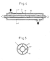
- Figs. 4 and 5 show a detail of the cooler 5 which is formed as a double circular tube structure.
- the cooler 5 includes an inner tube 51 for a passage of the flow of the refrigerating CO 2 , an outer tube 52 for a passage of the flow of the injecting CO 2 , and radially extending fins 53 arranged between an outer cylindrical surface of the inner tube 51 and an inner cylindrical surface of the outer tube 52.
- an inner tube 51 is made from a metal material of an increased heat conduction factor such as an aluminum and the outer tube 52 is made of a metal material of a reduced heat conduction factor.
- the inner and outer tubes 51 and 52 and the radially extending fins 53 are made integrally from an aluminum by, for example, an extrusion process.
- a heat insulating layer of a heat insulating material such as a foamed resin, is provided at the surface of the outer tubular part 52.
- a depression of a start switch causes the CO 2 refrigerating cycle to commence and the routine in the flowchart in Fig. 6 to commence.
- the control circuit 10 reads data as detected by the sensors 11 to 15.
- a calculation of a target temperature (TEO) of cooled air for obtaining a desired air conditioning effect is done based on the detected signals from the inside air temperature sensor 14, the outside air temperature sensor 15 and the temperature setter 15.
- TEO target temperature
- the routine goes, then, to step 110, where a determination is done if the target air temperature TEO calculated at step 110 is higher than the temperature T 1 of the air at the outlet of the evaporator 7 detected by the evaporator downstream air temperature sensor 11.
- a determination of TEO > T 1 means that a thermal load is high and the refrigerating capacity is lacking.
- the routine goes to step 130, where a calculation of the degree T is of the super heating at the outlet of the cooler 5 is done in accordance with the temperature of the CO 2 at the outlet of the cooler 5 by the temperature sensor 12 and the pressure of the CO 2 at the outlet of the cooler 5 by the pressure sensor 13.
- the routine flows into a step 140, where it is determined if a predetermined degree of super heating, T in is higher than the target value of the super heating degree T is calculated at the step 130.
- a determination of T in > T is causes the routine to go to step 150, where an increase of a predetermined value in the degree of the opening A of the sub pressure reducer 4 is obtained. Then, the routine goes back to the step 100 for a repetition of the operation.
- the routine goes to step 160, where a determination is done if the degree of the opening A of the first pressure reducer 4 is not zero, i.e., the first pressure reducer is not fully closed, the routine goes to step 170, where a decrease of a predetermined value in the degree of the opening A of the sub pressure reducer 4 is obtained and the routine goes back to the step 100 for the repetition of the operation.
- the commencement of the operation of the refrigerating system by the start switch causes the routine to go to step 200, where detected values by the temperature sensor 17 are read out, and then to step 210, where a calculation of a target value (P in ) of the pressure at the inlet of the main pressure reducer 3 is done.
- a map is stored in the ROM of the control circuit 10 which corresponds to a relationship between the temperature of the refrigerant at the inlet of the main pressure reducer 3 and a pressure of the refrigerant at the inlet of the main pressure reducer 3 as shown in Fig. 8.
- An interpolation is done using the map in Fig. 8 to obtain a value of the pressure P in at the inlet of the pressure reducer 3 corresponding to the detected temperature of the CO 2 by the sensor 17.
- a pressure P 1 of the refrigerant at the inlet of the main pressure reducer 3 detected by the sensor 18 is read out. Then, at step 230, it is determined if P in > P 1 . If it is determined that the target value P in of the pressure at the inlet of the main pressure reducer 3 is higher than the detected pressure P1 at the inlet of the pressure reducer 3, the routine goes to a step 240, where the degree of the opening of the main pressure reducer 3 is decreased to a predetermined value.
- the routine goes to a step 250, where the degree of the opening of the main pressure reducer 3 is increased for a predetermined value. Then, the routine goes back to the step 200 for a repetition of the above process.
- an increase in the pressure of the CO 2 is needed at the outlet of the heat emitter 2.
- an increase in the pressure at the outlet of the heat emitter 2 is accompanied with an increase in the discharging pressure at the compressor 1, resulting in an increase in a compression work, i.e., an amount of a change in enthalpy, ⁇ L during a compression phase A-E by the compressor 1 as illustrated in a Mollier chart in Fig. 1.
- a solid curve shows a relationship between the pressure at the outlet of the heat emitter 2 and the value of the coefficient of performance which is calculated by using Mollier chart in Fig. 1, while assuming that the temperature of the refrigerant (CO 2 ) at the outlet of the heat emitter 2 is 40°C.
- a maximum value of the coefficient of performance (COP) is obtained when the pressure is P 1 , which is about 10 MPa.
- a dotted curve shows a similar relationship when the temperature of the refrigerant (CO 2 ) at the outlet of the heat emitter 2 is 30°C.
- a maximum value of the coefficient of performance is obtained when the pressure is P 2 , which is about 8.0 MPa.
- a thick solid line ⁇ max in Fig. 1 which is herein referred as a optimum control line, is obtained.
- a degree of subcool at the inlet of the main pressure reducer 3 is in a range between 1 to 10°C.
- the optimum control line ⁇ max is shown in the rectangular coordinate system when the pressure in the evaporator 7 is about 3.5 MPa (corresponding to the temperature of 0°C at the evaporator 7) and the degree of sub-cool is about 3°C.
- the pressure at the outlet of the heat emitter 2 (the pressure at the inlet of the main pressure reducer 3) is increased or decreased.
- the pressure at the outlet of the heat emitter 2 is determined not only by the degree of the opening of the main pressure reducer 3 but also by the degree of the opening of the sub pressure reducer 4.
- the maximum and the minimum pressure during the execution of the refrigerating cycle are largely influenced by the degree of the opening of the main pressure reducer 3.
- the pressure at the outlet of the heat emitter 2 is substantially determined by the degree of the opening of the main pressure reducer 3.
- a heat exchange occurs between the injecting CO 2 and the refrigerating CO 2 , so that a reduction of a specific enthalpy of the refrigerating CO 2 at the inlet of the main pressure reducer 3 is obtained.
- Such a reduction of a specific enthalpy of the CO 2 at the inlet of the main pressure reducer 3, i.e., a reduction of a specific enthalpy of the CO 2 at the inlet of the evaporator 7 does not accompany any increase in the pressure of CO 2 at the outlet of the heat emitter 2.
- a line B-C illustrates a heat emission by the heat emitter 2
- a line C-D illustrates a pressure reduction by the main pressure reducer 3
- a line D-A illustrates an evaporation at the evaporator 7.
- a part of the CO 2 is diverted from the main passageway 27 at a location C' in Fig. 10 and is passed through the sub-passageway 28, so that a pressure is reduced to a point D' at the first pressure reducer 4.
- the CO 2 in the passageway 28 is injected into the compressor 1.
- Such an injection of the CO 2 causes the temperature of CO 2 corresponding to a specific enthalpy to be reduced since a change in state in a Mollier chart from a point X to a point X' is generated as shown in Fig. 10.
- the condition of the CO 2 in the compressor is varied along an isothermal line corresponding to a reduced temperature of the CO 2 .
- the isothermal line after injection has an increased gradient with respect tc the specific enthalpy over the isothermal line prior to the injection.
- the present example where the CO 2 injection is done to the compressor 1 when a compression is partially done can reduce a compression work over a case where no injection into the compression is done, i.e., a mere induction and compression of CO.. is done.
- the present example can provide an increased value of a coefficient of performance.
- the coefficient of performance in the refrigerating system using CO 2 is varied in accordance with various operating conditions including the pressure at the inlet of the evaporator 7 (intake pressure), the pressure at the outlet of the heat emitter 2 (outlet pressure) and the pressure of CO 2 as injected.
- the inventors have conducted a test under a fixed pressure at the outlet of the heat emitter 2 of 10 MPa, while varying the pressure at the inlet of the evaporator 7 in a range between 3.5 to 4.2 MPa and varying the pressure of the injected CO 2 .
- the maximum value of the coefficient of performance is obtained when the pressure of the injected CO 2 is about 6,5 MPa.
- the CO 2 refrigerating cycle is carried out while keeping an increased value of the coefficient of performance when a selection of the pressure P i of the CO 2 for injection is done so that a ratio of the pressure difference ⁇ P s between the pressure P i of the injected CO 2 injected to the compressor 1 and the pressure P s of CO 2 sucked to the compressor 1 from the evaporator 7 to the pressure difference ⁇ P d between the pressure P d of CO 2 discharged from the compressor 1 and the pressure P i of the injected CO 2 , ⁇ P s / ⁇ P d is maintained in a range between 0.6 to 0.9.
- a specific enthalpy of the CO 2 at the inlet of the evaporator 7, which corresponds to a degree of a sub-cool is controlled, resulting in an increase in the refrigerating performance of the refrigerating system using CO 2 without using an ON-OFF control of the electromagnetic clutch or a capacity control of a variable displacement type of compressor.
- a chance of an occurrence of ON-OFF operation of the electromagnetic clutch is reduced, which otherwise irritate a driver or passenger.
- use of a capacity control mechanism in a compressor is eliminated, thereby preventing the production cost from being increased.
- a pressure and a temperature at the outlet side of the heat emitter 2 is controlled so that they follow the optimum control line ⁇ max , which cooperates with the effect of a cooling capacity increase by the cooler (heat exchanger), thereby increasing the coefficient of performance while keeping an increased refrigerating performance of the refrigerating system executing a refrigerating cycle using CO 2 .
- the pressure reducer 4 may constructed as an ON-OFF type valve, which is subjected to a duty control in a well known manner.
- a pressure reducing device 400 is constructed by a pressure reducer unit 410, which has substantially the same construction as that of the pressure reducer 4 in the first example in Fig. 2 and by a thermal expansion valve 420 which is similar construction to that used for a conventional type refrigerating system using flon.
- the pressure reducer 410 includes a valve member 411 located in the injection passageway 28 between the heat emitter 2 and the heat exchanger 5 as shown in Fig. 2.
- the thermal expansion valve 420 includes a heat sensing tube 421 located at a position suitable for detecting a temperature of CO 2 at the outlet of the cooler 5 in Fig. 2. In a well known manner, a gas such as CO 2 is sealingly stored in the heat sensing tube 421.
- the thermal expansion valve 420 is further provided with a bellows member 422 which has a chamber opened to the heat sensing tube 421, a return spring 423 urging the bellows member 422 upwardly, and a valve member 424 connected to the bellows member 422.
- the valve member 424 is located in the passageway 28 at a location downstream from the valve member 411.
- the bellows member 422 is displaced in accordance with the pressure at the outlet of the cooler 5 detected by the thermo-tube 421.
- the lift of the valve 424 is controlled in accordance with the pressure at the outlet of the cooler 5.
- a degree of super heating at the outlet of the cooler 5 is controlled mechanically by means of the thermo sensitive expansion valve 420.
- the valve member 411 in order to control the cooling capacity of the cooler 5, the valve member 411 is connected to a step motor 412, so that the valve member 411 is controlled continuously from a fully closed position to a fully opened condition by using the step motor 412.
- a mere ON-OFF type electromagnetic valve can be used. Namely, the electromagnetic valve is opened when an increased refrigerating capacity is necessary in summer season. Contrary to this, the electromagnetic valve is closed when a small refrigerating capacity is sufficient in winter season or a mere defrosting operation is done.
- an operation is simplified, thereby reducing, on one hand, a production cost and increasing a reliability during the execution of the CO 2 refrigerating cycle, on the other hand.
- the electromagnetic valve can be subjected to a duty control in accordance with the desired refrigerating capacity.
- the electromagnetic valve is controlled such that if a larger refrigerating capacity is required a larger duty ratio is provided.
- Fig. 13 shows a third example, which is different from the first example in Fig. 2 in that, in place of the accumulator 8 in Fig. 1, a receiver 19 is arranged in the refrigerant recirculating passageway at a location downstream from the main pressure reducer 3, so that, at the receiver 19, the CO 2 issued from the main pressure reducer 3 is separated to a gaseous phase and a liquid phase and in that a third pressure reducer 20 is arranged at the outlet of the receiver 19, so that a pressure of the liquid state CO 2 from the receiver 19 is reduced and a mass flow amount of the CO 2 is controlled in such a manner that the degree of the super heating at the inlet of the compressor 1, i.e., at the outlet of the evaporator 7, is controlled to a predetermined value.
- the third pressure reducer 20 is of the same structure at that of an expansion valve used in a conventional refrigerating system using as a refrigerant flon. Namely, the third pressure reducer is provided with a heat sensitive tube 21 at the outlet of the evaporator 7, so that the degree of the opening of the third pressure reducer 20 is controlled in accordance with the pressure inside the heat sensitive tube.
- the Japanese Examined Patent Publication No. 7-18602 proposes an accumulator arranged at the outlet side of the evaporator 14 which functions to separate the liquid phase and the gaseous phase, so that only the gaseous phase of the CO 2 is fed to the compressor 10.
- a lubricant of an increased density compared to the gaseous phase CO 2 is likely to be held in the accumulator.
- the above mentioned '602 patent proposes an arrangement of the accumulator for preventing a shortage of the lubricant in the compressor such that a phase separation is done at the accumulator, while the lubricant is taken out at a lower portion of the accumulator under the effect of a gravity by utilizing a fact that the lubricant has an increased density over the liquid phase of the CO 2 , and the lubricant as taken out is returned back to the inlet side of the compressor as well as to the outlet side of the accumulator.
- sucking of a liquid phase of the CO 2 to the compressor, which causes the compressor to be damaged, and seizing of the compressor due to a lack of the lubricant is prevented, while maintaining an increased efficiency of the refrigerating cycle using the CO 2
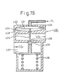
- a sub pressure reducer 430 is arranged so that the degree cf the opening of the pressure reducer 430 is controlled in accordance with the pressure P L at the side of the evaporator 7.
- the sub pressure reducer 430 is constructed by a diaphragm 431, a housing 432 for holding the diaphragm 431 at its outer peripheral portion, so that a first pressure chamber 433 is formed above the diaphragm 431 and a second chamber 433' is formed, below the diaphragm 431, which is opened to the atmosphere via a hole 434.
- the valve 430 is further provided with a rod 435 connected to the diaphragm 431, a valve port 438, a valve ball 439 contacting with the rod 435, a spring 436 which urges the valve ball 439 upwardly, and a passageway 437 for the CO 2 arranged between the outlet side of the heat emitter 2 and the heat exchanger 5.
- the connecting rod 435 passes through the valve port 435 and is contacted with the valve member 439 which is urged upwardly by the coil spring 436.
- the pressure P L in the diaphragm chamber 433 generates a force, which is acts on the valve member 439 in a direction opposite to the direction of the valve closing force FS and which is referred herein below as a valve opening force F o .
- an increase in a thermal load in the evaporator 7 causes a pressure PL to be increased at the side of the evaporator 7, thereby increasing the valve opening force FO, which finally causes the latter to overcome the valve closing force FS.
- the degree of the opening of the sub pressure reducer 430 is increased, which results in an increase in the amount of CO 2 injected into the compressor 1 via the passageway 28.
- a decrease in a thermal load in the evaporator 7 causes a pressure PL to be reduced at the side of the evaporator 7, thereby reducing the valve opening force FO, which finally causes the latter to be smaller than the valve closing force FS.
- the degree of the opening of the sub pressure reducer 430 is decreased, which results in a decrease in the amount of CO 2 injected into the compressor 1 via the passageway 28.
- an accumulator 8' is arranged also at the outlet of the cooler 5.
- a thermal expansion valve 420 may be arranged at a location downstream of the sub pressure reducer 430, including a location downstream of the cooler 5, similar to the second and fifth examples.
- a reference numeral 600 denotes a main pressure reducer in this example.
- Fig. 16 which illustrates a detail of the main pressure reducer 600, the latter includes a housing 613 defining a passageway 601 for connecting the cooler 5 with the evaporator 7 and a passageway 602 for connecting the heat emitter 2 with the cooler 5, a valve cover 610, a diaphragm 611, a closed diaphragm chamber 612 between the housing and the cover 610, an opened diaphragm chamber 612', an upstream chamber 615, a downstream chamber 616, a valve port 617, a valve member 618, a valve rod 619, a return spring 620 and a spacer 621.
- the CO 2 is stored at a density of about 600 kg/cm 3 with respect to the volume of the closed chamber 612 under a closed condition of the valve port 617.
- the housing 613 is further formed with a partition 614 dividing the chamber 615 and 616 with each other and forming the valve port 617, which is opened or closed by the valve member 618.
- the valve member 618 is connected to the diaphragm 611 via the rod 619, while an arrangement of the spring 620 is such that the valve member 618 is seated on the valve port 617 under the force of the spring 620.
- the pressure in the closed chamber 612 generates a force for urging the diaphragm 611 to more downwardly against the force of the spring 620.
- the degree of the opening of the valve port 617 is determined by the lift of the valve member 618 which is determined in accordance with the difference between a downwardly directed force as a sum of a force of the spring 620 and a force of the pressure in the closed space 612 and an upwardly directed force of the pressure at the chamber 615, which is opened to the lower diaphragm chamber 612'.
- the spacer 621 is for controlling an initial load of the spring 620, which allows a predetermined load to be generated in the spring 620.
- the value of the initial set force of the spring 620 corresponds to one which corresponds to a pressure of 1 MPa generated in the diaphragm 611.
- the CO 2 is sealingly stored under a pressure of about 600 kg/m 3 , which causes the pressure and the temperature in the chamber 612 to be varied along the isobaric pressure lines of 600 kg/m 3 as shown in Fig. 1.
- the inner pressure is about 5.8 MPa.
- the inside pressure in the closed chamber 612 and the initial set force of the coil spring 620 are simultaneously applied to the valve member 618.
- the total force applied to the valve member 618 is about 6.8 MPa.
- valve member 618 moves downwardly to close the valve port 617, while when the pressure at the chamber 615 exceeds 6.8 MPa, the valve member 618 moves upwardly to close the valve port 617.
- the inner pressure is about 9.7 MPa.
- the total force applied to the valve member 618 is about 10.7 MPa.
- the valve member 618 moves downwardly to close the valve port 617, while when the pressure at the chamber 615 exceeds 10.7 MPa, the valve member 618 moves upwardly to open the valve port 617.
- the isobaric line of 600 kg/m 3 substantially coincides with the above mentioned optimum control line ⁇ max .
- the main pressure reducer 600 can increase the pressure at the outlet side of the heat emitter 2 to those which are substantially located along the optimum control line ⁇ max , which allows the refrigerating cycle using CO 2 to be effectively executed.
- the density of the CO 2 stored at the closed space 612 is, from the practical view point, in a range from a value of a density of the saturated liquid when the temperature of CO 2 is 0°C to a value of a density of the saturated liquid at the critical point of CO 2 , and, in detail, in a range between 450 kg/m 3 and 950 kg/m 3 .
- this example can maintain an increased value of a coefficient of performance, while increasing a refrigerating performance and reducing a number of parts constructing the refrigerating system. In other words, an increased reliability is obtained, while reducing the production cost.
- the temperature at the closed space 612 of the main pressure reducer 600 is varied, without any accompanying delay, in accordance with the temperature at the outlet side of the heat emitter 2, which corresponds to the temperature of the CO 2 at the conduit 602.
- the valve cover 610 and the valve housing 613 are located in the passageway 602.
- the valve cover 610 and the valve housing 613 must have a coefficient of a heat conduction of as large as possible and a thickness as large as possible.
- the valve cover 610 and the valve housing 613 are made of brass, and the diaphragm 611, a valve member 618, the coil spring 620 and the spacer 621 are made of a stainless steel.
- fins may be provided for increasing a heat transfer coefficient between the CO 2 in the passageway 602 and the valve cover 621.
- the accumulator 8' is arranged in order to prevent liquid phase CO 2 being sucked into the compressor.
- the fifth example features that the accumulator 8' is eliminated.
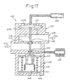
- the system in this fifth example is shown in Fig. 17 includes a sub pressure reducer 430, which is constructed by a device for controlling the degree of the opening of a controller 431 of the sub pressure reducer 430 in such a manner that the degree of a heating at the outlet side of the cooling device 5 does not exceed a predetermined value and a load responding part 432 which is for controlling the degree of the opening of the sub pressure reducer 430 in accordance with the thermal load in the evaporator 7.
- a sub pressure reducer 430 which is constructed by a device for controlling the degree of the opening of a controller 431 of the sub pressure reducer 430 in such a manner that the degree of a heating at the outlet side of the cooling device 5 does not exceed a predetermined value
- a load responding part 432 which is for controlling the degree of the opening of the sub pressure reducer 430 in accordance with the thermal load in the evaporator 7.
- the controller of the degree of the heating comprises a heat sensitive tube 433, which is arranged at the outlet side of the cooler 5 for detecting the temperature of CO 2 at the outlet side of the cooler 5, and a housing having a partition wall 434 for dividing the passageway for the CO 2 to be injected into an upstream portion and a downstream portion.
- the partition wall 434 is formed with a valve port 436, which is located between the upstream portion and the downstream portions.
- a diaphragm 437 which is responsive to the change in the pressure (temperature) at the heat sensitive tube 433, is provided and is connected to a valve member 438.
- the diaphragm 437 forms, at its one side, a chamber 437a which is opened to the space inside the thermo sensitive tube 433 and, at its other side, a chamber 437b in communication with the passageway 435 downstream from the valve port 436.
- the pressure at the chamber 437a urges, via the diaphragm 437.
- the valve member 438 to move so that the degree of the opening of the valve port 436 is increased.
- the pressure in the chamber 437b together with the spring 442 causes the valve member 438 to move so that the degree of the opening of the valve port 436 is reduced.
- a reference numeral 439 denotes a thermo-sensitive tube arranged at a location downstream from the evaporator in the air flow or at a location at the outlet of the CO 2 from the evaporator 7. Inside the thermo-sensitive tube 439, a gas such as a flon or propane is sealingly stored at a predetermined density. The gas sealed space of the thermo-sensitive tube 439 is in communication with a bellows 440. A first plate 441 is connected to the bellows 440 at its one end in a direction of a contraction or expansion movement of the bellows 440.
- a second plate 443 is arranged, so that the second plate 443 is connected to the first plate 441 via a spring 442.
- the valve member 438 of the heating degree controller 430 Connected to the second plate 443 is the valve member 438 of the heating degree controller 430.
- the spring 442 generates a spring force, which causes the valve member 438 to be moved so that the valve port 436 is closed by the valve member 438.
- the bellows 440 is, at its upper end, fixedly connected to a part of the housing 444, so that the space inside the bellows 440 is in a communication with the space inside the thermo-sensitive tube 439 via a passageway in the housing 444.
- a reference numeral 445 is an O-ring which prevents the pressure in the CO 2 passageway 435 from being opened to the chamber in which the bellows 440 is arranged.
- a decrease in a thermal load of the evaporator 7 causes the pressure to be reduced at the space inside thermo-sensitive tube 439, which causes the bellows member 440 to be contracted, resulting in a downward movement of the first plate 441. Due to this downward movement of the first plate 441, the degree of the opening of the valve port 436 is decreased, thereby reducing a flow amount of CO 2 , which reduces the enthalpy difference between the inlet and the outlet of the evaporator 7.
- the compression by the compressor 1 is executed by a series of compressors.
- a ratio of the volume V d of the second compressor to the volume V s of a first stage compressor, in a range 0.8 to 1 corresponds to the ratio of the pressure difference ⁇ P s to the pressure difference ⁇ P d , in a range 0.6 to 0.9.
- a single compressor may have a first operating chamber adjacent the evaporator 7 and a second operating chamber adjacent the heat emitter.
- the ratio of the volume V d ' of the second (high pressure) operating chamber adjacent to the heat emitter to the volume V s ' of the first (low pressure) operating chamber adjacent the evaporator 7 may be in a range 0.8 to 1.
- a sixth example of the present invention is directed to a second aspect, which is directed to an increase in a cooling capacity.
- the coefficient of a performance is a ratio of the change in the enthalpy, ⁇ i at the evaporator to the compression work ⁇ L.
- the maximum value of the coefficient of performance does not necessarily provide a cooling capacity for obtaining a desired cooling effect in the cabin.
- a control of a pressure reducer is done so that a desired cooling capacity is obtained.
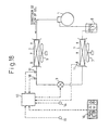
- Fig. 18 showing a construction of the refrigerating system in the example and parts with functions to similar those in the first example (Fig. 2) are indicated by the same reference numerals.
- the refrigerating system is basically constructed by the compressor 1, the heat emitter 2, the pressure reducer 3, the evaporator 7 and the accumulator 8.
- the refrigerating system in Fig. 18 is not provided with the sub pressure reducer 4, and the heat exchanger 5 and the CO 2 injection conduit.
- the pressure reducer 3 functions also as a pressure control means for controlling the pressure at the outlet side of the heat emitter 2 in accordance with the pressure at the outlet side of the temperature of the CO 2 . Namely, as will be fully explained later, the pressure at the outlet side of the heat emitter 2 is increased to a predetermined value and then reduced, thereby producing a gas-liquid combined state of the CO 2 .
- a detailed construction of the pressure reducer 3 is similar to that is shown in Fig. 3 with reference to the sub pressure reducer in the first example.
- control circuit 10 is connected to the evaporator-downstream air sensor 11, the cabin air temperature sensor 14, the outside air temperature sensor 15, the temperature setter 16, the emitter outlet CO 2 temperature sensor 17 and the emitter outlet pressure sensor 18 and functions to control the operation of the pressure reducer 3 as will be fully explained later.
- the control circuit also functions, in a well known manner, to control an air mix door (not shown) and the fan 9', so that an amount and a temperature of the air discharged to the cabin are controlled.
- the pressure at the outlet of the heat emitter 2 located on the optimum control line ⁇ max (Fig. 1) is not univocally determined by the temperature of the CO 2 at the outlet of the heat emitter 2 but by a variation in the pressure in the evaporator 7, i.e., a variation in a heat amount imparted to the evaporator 7, which corresponds to a thermal load of the evaporator 7.
- a continuation of an operation causes the cabin temperature to be gradually stabilized to an equalized value which is determined by the evaporating temperature of the refrigerant, the heat exchanging capacity of the evaporator 7 and a heat inflow from the atmosphere tc the cabin.
- the pressure variation on the side of the evaporator 7 is gradually stabilized.
- a determination of the optimum control line ⁇ max is done in accordance with the pressure at the evaporator 7 which corresponds to the evaporating temperature of the CO 2 in the evaporator 7.
- Fig. 8 shows a target pressure (a first target pressure) with respect to the inlet side pressure of the pressure reducer 3, i.e., pressure at the outlet of the heat emitter 2, when the pressure at the evaporator 7 is 3.5 MPa which corresponds to the CO 2 evaporating temperature (0°C).
- the pressure at the evaporator 7 is increased, which causes the temperature of the CO 2 in the evaporator 7 as well as the pressure at the evaporator 7 to be increased.
- a sufficient refrigerating capacity for a desired refrigerating capacity of the refrigerating system using CO 2 cannot be obtained by the target pressure for the maximum value of the coefficient of a performance at the pressure of the evaporator of 3.5 MPa.
- the sixth example increases, in accordance with the increase in the load, the target pressure to a value larger than the first target value by reducing the degree of the opening of the pressure reducer 3, thereby increasing the refrigerating capacity.
- a temperature T v of the CO 2 at the inlet of the pressure reducer 3 measured by the temperature sensor 17 is read out.
- a temperature T set set by the setter 16 manipulated by a driver or passenger is read out.
- a temperature T r of the cabin detected by the room temperature sensor 14 is read out.
- a difference ⁇ T between the room temperature and the set temperature, T r - T set is calculated.
- a result of a determination of ⁇ T ⁇ T o indicates that the thermal load of the evaporator 7 is smaller than a predetermined value and the routine goes to step 150, where a calculation of the first target value is done by using a table corresponding to the relationship between the temperature at the inlet of the pressure reducer 3 and the target value of the pressure of the CO 2 at the inlet of the pressure reducer 3, as shown in Fig. 8. Namely, an interpolation using the map is done to calculate the first target value corresponding to the temperature T 2 at the inlet of the pressure reducer 3 detected by the temperature sensor 17.
- a result of a determination of ⁇ T > T o at step 140 indicates that the thermal load of the evaporator 7 is larger than a predetermined value, i.e., a rapid cooling mode and the routine goes to step 160, where a calculation of the second target value is done as the first target value plus a pressure increase.
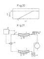
- Fig. 20 shows a relationship between the temperature difference ⁇ T between the cabin temperature T r and this set temperature T set and the pressure increase ⁇ T. This relationship is stored in a memory in the control circuit 10 and an interpolation using the map is done to calculate the pressure increase ⁇ P corresponding tc the value of the pressure difference ⁇ T obtained at the step 130.
- the second target pressure is obtained by adding the calculated pressure difference ⁇ P to the first target value calculated by the temperature T v at the inlet of the pressure reducer 3 in the similar way as that in step 150 by using the map in Fig. 8
- a pressure T in at the inlet of the pressure reducer 3 detected by the pressure sensor 18 is read out.
- a determination that the target pressure is larger than T in causes the routine flows into a step 190, where the pressure reducer 3 is controlled so that the degree of the opening is reduced.
- a determination that the target pressure is equal to or smaller than the detected pressure T in causes the routine to go to step 200, where the pressure reducer 3 is controlled so that the degree of the opening is increased.
- ⁇ P has the maximum value of 2.7 MPa as shown in Fig. 20.
- the pressure at the inlet of the pressure reducer 3 is controlled so that it is equal to the first target value (step 150).
- the CO 2 refrigerating cycle is executed while maintaining an increased coefficient of performance.
- the pressure at the inlet of the pressure reducer 3 is controlled so that it is equal to the second target value (step 160).
- the degree of the opening the pressure reducer 3 is decreased in accordance with the increase in the thermal load, thereby increasing the pressure of CO 2 at the inlet of the pressure reducer 3.
- a desired refrigerating capacity is obtained even if the refrigerating load is increased in the rapid refrigerating operation.
- the CO 2 refrigerating system is executed with a high efficiency, while obtaining a sufficient cooling capacity even under a high load condition such as a rapid refrigerating mode.
- an increase or decrease in the refrigerating capacity is mainly determined by an increase or decrease by an amount of the refrigerant (flon) recirculated in the system.
- the refrigerating capacity of the system is determined substantially only by the maximum flow amount of the flon.
- an increase or decrease of the refrigerating capacity is done by an increase or decrease of the pressure at the outlet of the heat emitter 2, i.e., the pressure at the inlet of the pressure reducer 3.
- a capacity of the compressor 1 is decided based on the mass flow amount of the CO 2 under a thermally stable condition of the evaporator 7, thereby preventing the size of the compressor 1 from being increased.
- the thermal load of the evaporator 7 is determined by detecting the difference ⁇ T in the temperature T r in the cabin and the set temperature T set .
- a temperature setting means in Fig. 18 constructed by the sensor 12 for detecting the room temperature 12 and the temperature setter 16 is eliminated in order to reduce the production cost.
- a pressure reducer 30 is provided.
- a means is provided for controlling the degree of the opening of the pressure reducer 30 such that the difference ⁇ P between the pressure at the outlet of the heat emitter 2, i.e., the inlet of the pressure reducer 30 and the pressure at the inlet of the evaporator 7, i.e., the outlet of the pressure reducer 30 is controlled to a target pressure difference which is determined in accordance with the temperature of the CO 2 at the outlet of the heat emitter 2 (the inlet of the pressure reducer 30).
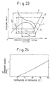
- the pressure reducer 30 includes a housing 50 defining an inlet port 51A connected to the heat emitter 2, an outlet port 51B connected to the evaporator 7, a valve port 52, a valve member 54 facing the valve port 52, a spring 56 urging the valve menber 54 to close the valve port 52, a step motor 58 for generating a rotating movement and a shaft 60 for adjusting a spring force of the spring 56.
- the coil spring 56 is at its one end rested on a first spring seat 62, which is connected to the valve member 54 and at its other end rested on a second spring seat 64 for adjusting the spring force of the spring 56.
- the second spring seat 64 is formed with a female screw thread 64a, to which a male screw portion 60a of the screw shaft 60 engages and with an axial groove to which a key 66 is engaged.
- a rotating movement of the adjusting shaft 60 by the step motor 58 causes the second spring seat 64 to be axially moved, thereby changing the spring force of the spring 56.
- An O-ring 68 is arranged between the housing 50 and the shaft 60 for a desired sealing function.
- the refrigerating system executing the refrigerating cycle using CO 2 generates a pressure which is about eight times larger than that in the conventional refrigerating system using flon.
- the O-ring 68 is located at a position as near as possible to the outlet port 51B.
- the step motor 58 is subjected to a control so that a target pressure difference is obtained in accordance with the temperature of CO 2 at the inlet of the pressure reducer 30.
- the pressure at the inlet 51A of the pressure reducer 30 generates a force F 1 in the valve member 54 for causing it to be moved upwardly to open the valve port 53.
- the pressure at the inlet of the evaporator 7 and the spring 56 generate a force F 2 in the valve member 54 to cause it to be moved downwardly to close the valve port 52.
- the valve member 54 is moved downwardly to reduce the degree of the opening of the valve port 52, contrary to this, when the force F 2 is smaller than the force F 1 , the valve member 54 is moved upwardly to increase the degree of the opening of the valve port 52. Since the valve member 54 is stopped at a position where the forces F 1 and F 2 are equalized, the degree of the opening of the valve port 52 is determined in accordance with the spring force 56 generated in the spring 56. In other words, a pressure difference ⁇ P between a space 70A adjacent the inlet 51A and a space 70B adjacent the outlet 51B corresponds to the spring force applied to the valve member 54 from the spring 56. Furthermore, a lift of the valve member 54 is relatively small, so that a change in the spring force applied to the valve member 35 from the coil spring 36 is substantially negligible. Thus, a pressure difference ⁇ P between the spaces 70A and 70B is considered to be constant.
- the pressure difference ⁇ T is one which is obtained between the spaces 70A and 70B when the inlet of the evaporator 7 is at a vapor pressure corresponding the evaporating temperature of the CO 2 (3.5 MPa at 0°C as shown in Fig. 1) and the pressure at the outlet of the heat emitter 2 is at the pressure on the optimum control line ⁇ max (the first target pressure).
- an operation the pressure reducer 30 by the control circuit 10 is such that the first target value is calculated in accordance with the temperature of the CO 2 by using the map in Fig.
- step motor 58 of the pressure reducer 30 is operated to adjust the force of the spring 56 in order to obtain a pressure difference ⁇ P which corresponds to the difference between the calculated first target value and the evaporating pressure with respect to the evaporating temperature of CO 2 (0°C at 3.5 MPa).
- Fig. 23 shows relationships between a specific enthalpy and the pressure (Mollier chart) in the refrigerating system according to the seventh example.
- a solid line A is produced when the refrigerating capacity (thermal load) is high, while a dotted line B is produced when the refrigerating capacity is low.
- a solid line SL indicates a saturated liquid line, and a solid line C is an isothermal line.
- the temperature of the air cooled by the evaporator 7 is high.
- the pressure in the evaporator 7 and the evaporating pressure of the CO 2 are increased. See Fig. 24.
- the pressure at the outlet of the heat emitter 2 is reduced to a condition as shown by the curve B, which causes the pressure at the outlet of the heat emitter 2 to approach the pressure (first target value) on the optimum control line ⁇ max .
- the refrigerating cycle using CO 2 is executed at an increased efficiency, while generating a sufficient refrigerating capacity suitable for an operation of an increased thermal load, such as a rapid cooling mode.
- both of the temperature sensor and the temperature setter in the sixth example are eliminated and a similar function is obtained by controlling an execution of the CO 2 refrigerating cycle by a simple means for controlling a degree of an opening of the valve port 52 so that a predetermined value of a pressure difference is obtained between the outlet of the heat emitter 2 and the inlet of the evaporator 7.
- a reduction of a production cost of the refrigerating system is realized.
- a pressure at the outlet or inlet of the evaporator 7 is taken out by a capillary tube, and is used for operating the valve member 54 via a diaphragm.
- a temperature of the CO 2 at the outlet of the heat emitter 2 is detected by the temperature sensor. Contrary to this, in this eighth example, the temperature sensor is eliminated. Namely, in place of detecting the temperature of the CO 2 at the outlet of the heat emitter 2, an estimation of the temperature is done based on the temperature of the cabin detected by the sensor 15 as shown in Fig. 25 and the estimated temperature of the CO 2 at the outlet of the heat emitter is used for controlling the execution of the refrigerating cycle. In more detail, the temperature of CO 2 at the outlet of the heat emitter 2 is substantially determined by the outside air temperature and the refrigerating capacity of the heat emitter 2.
- a test is done to obtain a relationship between the outside air temperature and the temperature of CO 2 at the outlet of the heat emitter 2.
- Such a relationship is stored in a map in the computer 10, and a map interpolation calculation is done in order to calculate the temperature of the CO 2 at the outlet of the heat emitter 2 which corresponds to the detected outside air temperature sensed by the outside air temperature sensor 15 in Fig. 25.
- the sensor in order to detect a temperature of the CO 2 at the outlet of the heat emitter 2, it is necessary that the sensor is arranged at a location adjacent the outlet of the heat emitter 2, while the temperature sensor is provided with an insulator for thermally insulating the sensor from the outside atmosphere.
- a cost for the material for the heat insulation is added and working steps for attaching the temperature sensor and the heat insulating material is necessary, which increases the production cost of the refrigerating system.
- the provision of the temperature sensor is eliminated, which, on one hand, prevents a cost for the heat insulating material from being added and working steps for the attachment of the temperature sensor and the heat insulating material are eliminated, on the other hand. As a result, an increase in the production cost is prevented.
- an outside air temperature sensor is used, which is an essential part for a conventional air conditioning system for executing an automatic air control.
- a separate sensor 15 is unnecessary, which also serves for further reducing the production cost.
- the force of the spring 56 is controlled by the step motor 58.
- a pressure at the evaporator 7 is introduced into the pressure reducer, so that the pressure operates a pressure responsive member such as a diaphragm for controlling the spring force of the coil spring 56.
- a pressure at the evaporator 7 is detected, and an electric actuator is operated for controlling a degree of opening of the valve.
- the pressure sensor 18 can detect the pressure at the inlet of the heat emitter 2. However, it is necessary to compensate for the pressure loss in the case where the pressure loss is large.
- the accumulator 8 is eliminated.
- the refrigerant in the evaporator 7 is sucked and operates in the same way as the CO 2 recirculating system including an accumulator 8 does.
- Fig. 26 shows a construction of the refrigerating system using CO 2 in this embodiment, which is, basically, constructed by a compressor 1, a heat emitter 2, a first stage pressure reducer 3, a receiver 19, a second stage pressure reducer 20 and an evaporator 7.
- the pressure reducer 3 is of the same structure as that in Fig. 3 which is explained with reference to the first example.
- the first stage pressure reducer 3 reduces the CO 2 issued from the heat emitter 2 and controls the pressure at the outlet of the heat emitter 2 in accordance with the temperature of the CO 2 at the outlet of the heat emitter 2.
- a temperature sensor 17 and a pressure sensor 18 are arranged at the outlet of the heat emitter 2.
- the control circuit 10 controls the degree of the opening of the first pressure reducer 3 in accordance with the temperature of CO 2 detected by the sensor 17, so that the pressure at the outlet of the heat emitter 2 is controlled along the optimum line ⁇ max in Fig. 1 as explained with reference to the first example Fig. 1.
- the receiver 19 is arranged between the first and second pressure reducers 3 and 20 and functions to execute a phase separation of the CO 2 issued from the pressure reducer 3 between the liquid phase and the gaseous phase.
- the receiver 19 is constructed by a tank 72 for storing CO 2 , an inlet pipe 74 connected to the outlet of the pressure reducer 3 and an outlet pipe 76 which is connected to the inlet of the second pressure reducer 20.
- the inlet pipe 74 is opened to the space inside the tank 72 at an upper part, where a gaseous phase of the CO 2 is located while the outlet pipe 76 is opened to the space inside the tank 72 at a lower part, where a liquid phase of CO 2 is located.
- a strainer 78 is arranged so that the liquid state CO 2 in the tank is cleaned and is directed to the outlet pipe 76.
- the additional pressure reducer 20 is for reducing the pressure of the CO 2 issuing from the receiver 19 and for controlling the mass flow rate of CO 2 in such a manner that the degree of super heating of CO 2 is controlled to a predetermined value at the inlet of the compressor 1.
- a thermo-sensitive tube 21, in which CO 2 is sealingly stored at a predetermined density, is arranged at the inlet of the compressor 1 for detecting a change in the temperature of the CO 2 .
- the construction of the additional pressure reducer 20 is of the similar structure which is used for as a temperature type expansion valve in a conventional vapor pressure compression type refrigerating system using flon. Furthermore, the degree of the opening of the additional pressure reducer 20 is controlled in accordance with the pressure of CO 2 in the thermo-sensitive tube 21.
- compressor 1 is connected to a driving source such as an internal combustion engine or an electric motor.
- the heat emitter 2 is arranged at a front part of the vehicle so that a temperature difference as large as possible is obtained between the atmospheric air and the CO 2 in the heat emitter 2.
- An energization of a start switch (not shown) for the refrigerating system causes the routine to commence.
- the temperature of the CO 2 at the inlet of the pressure reducer 3 detected by the sensor 17 is read cut, and at step 410, a calculation of a set pressure P set at the inlet of the pressure reducer 3 is done.
- a relationship between the temperature and the pressure at the inlet of the pressure reducer 3 as shown in Fig. 8 in the first embodiment is stored in ROM, and a map interpolation is done in order to obtain a value of P set which corresponds to the detected temperature at step 400.
- a pressure P in of the CO 2 at the inlet of the additional pressure reducer 20 is read out by the pressure sensor 18. Then, at step 430, a determination is done if the target pressure P set calculated at the step 410 is larger than the detected pressure Pin at the step 420. A result of determination that P set > Pin causes the routine to go to step 440, where the degree of the opening of the pressure reducer 3 is decreased. Contrary to this, a result of determination P set ⁇ Pin causes the routine to go to step 450 where the degree of the opening of the pressure reducer 3 is increased.
- the control circuit 10 operates so that the degree of the opening of the main pressure reducer 3 is decreased for obtaining a target pressure at the inlet of the pressure reducer 3 as shown in Fig. 8. In other words, the pressure at the inlet of the pressure reducer 3 is correspondingly increased.
- the pressure at the inlet of the compressor 1 is increased, so that the degree of the superheat at the inlet of the compressor 1 is controlled to a predetermined value, which is in a range between 5 to 10°C.
- the control circuit 10 operates so that the degree of the opening of the pressure reducer 3 is increased for obtaining a target pressure at the inlet of the pressure reducer 3, thereby decreasing the pressure at the inlet of the pressure reducer 3. Due to the decrease in the degree of the opening of the valve 3, the pressure at the inlet of the compressor 1 is decreased, so that the degree of the superheat at the inlet of the compressor 1 is controlled to the predetermined value. As a result, a decrease in the density of the CO 2 at the inlet of the compressor 1 is obtained as shown in Fig.
- a relationship between the temperature and the pressure of the CO 2 at the outlet of the heat emitter 2 is controlled so that the refrigerating system operates along the optimum control line ⁇ max , thereby maintaining an increased efficiency of the execution of the refrigerating cycle.
- a predetermined value of the degree of the superheat of the CO 2 at the inlet of the compressor 1 is maintained by the operation of the additional pressure reducer 20, which prevents a liquid phase of the CO 2 from being sucked into the compressor, thereby preventing the compressor from being damaged.
- a sucking of the liquid phase of the CO 2 by the compressor 1 is prevented by above mentioned control of the degree of the superheat at the inlet of the compressor 1.
- an arrangement of an accumulator at the outlet of the evaporator 7 is eliminated as is the case in the prior art (Japanese Examined Patent Publication No. 7-18602).
- a phase separation does not occur at the outlet of the evaporator 7, which allows sufficient lubricant to be sucked to the compressor 1 entrained with the high speed of flow of the gaseous state of the CO 2 .
- a sucking of the liquid state CO 2 which would otherwise cause the compressor to be seized or damaged, is prevented, while maintaining a high efficiency of the execution of the CO 2 refrigerating cycle.
- a second embodiment of the present invention will be explained with reference to Fig. 29.
- This embodiment is directed to the third aspect of the present invention but is modified in that a cooler for cooling the CO 2 issued from the heat emitter 2, as explained in the first aspect, is used.
- a sub-pressure reducer 4 is arranged on the sub recirculation passageway 28 branched from the main recirculation passageway 27 at a branch point 27-1.
- a cooler 5 is arranged in the sub recirculation passageway 28 at a location downstream from the pressure reducer 4.
- a first and a second compressors 1a and 1b which are arranged in series are arranged in the main recirculating passageway 27.
- the first stage compressor 1a compresses the refrigerant from a pressure at the evaporator 7 to an intermediate pressure in a range between about 6.0 to 6.6 MPa and the second stage compressor 1b compresses the refrigerant from the intermediate pressure to the pressure at the heat emitter 2.
- the sub recirculation passageway 28 is, at its downstream end, connected to the main recirculation passageway at a point 27-2 located between the compressors 1a and 1b.
- the CO 2 is subjected to a pressure reduction at the pressure reduction valve 4 and is injected to the inlet of the second stage compressor 1b.
- thermo-sensitive tube 29 is provided also for the pressure reducer 4, so that a degree of the opening of the pressure reducer 4 is controlled in accordance with the temperature at the inlet of the compressor 1b, so that the degree of the super heat at the inlet of the compressor 1b is controlled to a predetermined value, thereby preventing a liquid phase of the CO 2 from being sucked by the second stage pressure reducer 1b.
- cooler (heat exchanger) 5 Construction of the cooler (heat exchanger) 5 is the same as shown in Figs. 4 and 5.
- the CO 2 issued from the heat emitter 2 is subjected to a cooling at the cooler 5, which reduces the specific enthalpy at the inlet of the main pressure reducer 3, thereby increasing a difference in the specific enthalpy between the inlet and the outlet of the evaporator 7, thereby increasing a refrigerating capacity.
- a gas-liquid separator for separating a gaseous phase is unnecessary at the inlet of the compressor 1a, which allows a sufficient amount of the gaseous phase of the refrigerant to be fed to the compressor 1a at an increased flow speed.
- the pressure reducer 4 on the sub recirculation passageway reduces the pressure to the intermediate pressure and is injected to the inlet of the second stage compressor 1b.
- the second stage compressor 1b executes a compression work by the CO 2 under the intermediate pressure. As a result, a coefficient of performance of the CO 2 refrigerating cycle is increased.
- a single stage compressor 1 as shown in Fig. 2 in reference to the first example, can be used.
- the cooler may constructed as a double tube structure similar to the structure shown in Figs. 4 and 5 as explained with reference to the first example.
- the cooler 5 is constructed as a double spiral structure having a first and second spiral shaped walls 80A and 80B forming a spiral shaped passageways 81A and 81B therebetween, and a top and bottom covers 82 and 84.
- the first spiral passageway 81A is for the CO 2 of a low pressure from the pressure reducer 4, i.e., the sub recirculating passageway 28.
- the pressure reducer 4 i.e., the sub recirculating passageway 28.
- CO 2 at a low temperature from the pressure reducer 4 is introduced into the passageway 81A at its central pipe 85A, flows in the spiral passageway 81A outwardly, is issued at an outer end 86A and is injected to the compression passageway in the compressor.
- CO 2 at a high temperature direct from the heat emitter 2 is introduced into the passageway 81B at its outer end 86B, flows inwardly, in the spiral passageway 81A issues from the central pipe 85B and is directed to the main pressure reducer 3.
- the low pressure CO 2 introduced from the center of the spiral shape flows outwardly while being subjected to heating.
- the high pressure CO 2 introduced from the outer end of the spiral shape flows inwardly while being subjected to cooling.
- an extruded strip 87 of an aluminum having an upper row of holes 87-1 and a lower row of holes 87-2, each extending along the length of the strip therethrough, is prepared as shown in Fig. 32.
- two of such strips 87 are, under a side by side condition, soldered and are wound to a spiral shape.
- the holes 87-1 and 87-2 of the one of the strips 87 form the first spiral passageway 81A, while the holes 87-1 and 87-2 of the other strip 87 form the second spiral passageway 81B.
- the sub-pressure reducer 4 and the cooler 11 are integrated.
- the cooler 5 is constructed by an inner U-shaped pipe 87 and an outer U-shaped pipe 88 and a connection block 89 made of an aluminum material, to which ends of the pipes 87 and 88 are connected.
- the inner pipe 87 has a first end 87-1 connected to the heat emitter 2 in Fig. 29 for receiving the CO 2 and a second end 87-2 connected to the main pressure reducer 3 in Fig. 3 issuing the CO 2 .
- the end connection block 89 is formed with a passageway 89-1 diverting a part of the CO 2 in the main recirculation passageway (27 in Fig.
- the pressure reducing valve 4 includes a valve member 90 located at the passageway 89-1 and a step motor 91 for controlling the position of the valve member 90.
- a temperature sensor 12 and a pressure sensor 13 are arranged at the outlet of the outer tube 88 in a similar way as that in Fig. 2.
- the detecting signals from the sensors 29 and 29' are supplied to the control circuit 10.
- the degree of super heat at the inlet of the second stage compressor 1b in Fig. 29 is calculated.
- Control of the step motor 91 is done so that a position of the needle 90, i.e., a degree of the opening of the pressure reducing valve 4, is adjusted so that a predetermined value of the degree of a super heat of CO 2 is obtained at the inlet of the compressor 1b.
- the pressure reducer 4 having a mechanical thermo-sensitive tube 29 and the cooler 5 of a double tube type constructed by the inner and outer tubes 87 and 88 in Fig. 34 are integrated.
- the pressure sensitive tube 29 is opened to a bellows member 29-1 which is connected to the valve 4.
- the bellows member 29-1 is subjected to shrinkage or expansion against the force of the spring 29-2, thereby controlling the position of the valve 4, i.e., the degree of the opening of the valve 4.
- the predetermined value of the super heat at the inlet of the compressor 1b in Fig. 29 is determined by the set force of the spring 29-2 which urges the valve 4 to take a closed position.
- the double tube type cooler 5 and the electrically controlled sub pressure reducer 4 in Fig. 34 are integrated with the electrically controlled main pressure reducer 4 controlled by the temperature sensor 17 and the pressure sensor 18 in Fig. 29.
- Fig. 37 shows the double tube type cooler 5 and the mechanically operated sub-pressure reducer 4 in Fig. 37, to which the pressure reducer 3 of a mechanically operated type is integrated.
- the pressure reducer 3 is constructed by a valve member 92, a spring 93 urging the valve member 92 to take a closed position, a rod 94 extending from the valve member 92 and a bellows member 95 connected to the rod 94 and arranged in the main recirculating passageway at a location upstream from the passageway 89-1.
- a force due to the spring 93 and a force due to the pressure in the sealed space 95A of the bellows member 95 cause the valve member 92 to take a closed position to close a valve port 96.
- CO 2 is sealingly stored at a density of about 600 kg/m 3 with respect to the inner volume of the space 95A when the valve 92 closes the valve port 96, while the initial set force of the spring is about 1 MPa. It is desirable that the sealing density of the CO 2 is in a range between the saturated liquid density when the temperature of the CO 2 is 0°C to the saturated liquid density at the critical point of the CO 2 and is practically in a range between 450 to 950 kg/m 3 .
- the mechanical pressure reducer valve 3 in Fig. 37 Since the CO 2 is sealingly stored in the closed space 95A at a density of about 600 kg/m 3 , the pressure and the temperature at the closed space 95A varies along the isobaric line of 600 kg/m 3 in Fig. 1. Thus, when the temperature at the space 95A is, for example, 20°C, the pressure at the space 95A is about 5.8 MPa. Furthermore, in addition to the pressure at the space 95A, the force of the spring 93 acts on the valve member 92, which makes the total force applied to the valve member to be increased to, for example, about 6.8 MPa.
- valve member 92 when the pressure at the heat emitter is 6.8 MPa or less, the valve member 92 closes the valve port 96. Contrary to this, when the pressure at the heat emitter larger than 6.8 MPa, the valve member 92 opens the valve port 96.
- the isobaric line of 600 kg/m 3 substantially conforms to the optimum control line ⁇ max in Fig. 1.
- the operation of the pressure reducer 3 causes the pressure at the outlet of the heat emitter 2 to increase to the pressure located adjacent the optimum control line ⁇ max , thereby allowing the refrigerating cycle using CO 2 to be operated at a high efficiency even at the super critical zone.
- the isobaric line of 600 kg/m 3 is spaced from the optimum control line ⁇ max , and is moved into a condensing zone.
- the pressure inside the space 95A is moved along the saturated liquid line SL.
- a set force of the spring 93 causes the system to be operated in a condition of sub-cooling of about 10°C.
- the CO 2 refrigerating cycle can be operated at a high efficiency.
- this embodiment is advantageous in its simplicity of the structure that the space 95A inside the bellows member 95 sealingly stores the CO 2 , resulting in a reduction of total number of parts of the system, thereby reducing a production cost, while allowing the pressure at the outlet of the heat emitter to be controlled along the optimum control line ⁇ max .
- a cooler 5 for cooling the gaseous CO 2 to be injected into the inlet of the second stage compressor 1b is eliminated.
- a conduit 700 is provided, which has an upstream end opened to the space inside the receiver 19 above the liquid level of the CO 2 and a second end connected to the main recirculating passageway 27 at a location between the compressors 1a and 1b.
- the line A-A' is a first stage compression by the compressor 1a
- the line A"-B is a second stage compression by the compressor 1b
- the line B-C is heat emission
- the line C-C' is the first stage expansion by the pressure reducer 3
- the line C-A'' is a gas injection from the conduit 700
- the line C'-C'' is liquidation at the receiver 19
- the line C"-D is a second stage expansion by the pressure reducer 20
- the line D-A is evaporation at the evaporator 7.
- the difference of the specific enthalpy between the inlet and the outlet of the evaporator 7 is ⁇ 1, which is increased over that in the system in Fig. 29 expressed by ⁇ 2.
- the gaseous stage CO 2 is injected to the second compressor 1b, resulting in a reduction in the compression work by the second stage compressor 1b.
- an increase in the difference in the specific enthalpy between the inlet and the outlet of the evaporator 7 is obtained, while preventing compression work from being increased in, the compressor 1b, thereby increasing a refrigerating capacity by the execution of the CO 2 according to this embodiment. Therefore, an increase in the difference in the specific enthalpy between the inlet and the outlet of the evaporator 7 is obtained, while keeping a reduced compression work done by the compressor 1b, thereby increasing a refrigerating capacity as well as a coefficient of performance during the execution of the CO 2 refrigerating cycle.
- the degree of the openirg of the pressure reducer 3 is controlled by the controller 10 in accordance with the detected values of the temperature sensor 17 and the pressure sensor 18.
- the degree of the opening of the pressure reducer 20 is controlled in accordance with the pressure of the CO 2 sealingly stored in the thermo-sensitive tube 21.
- Figs. 40 and 41 illustrate an actual structure cf the receiver 19 in Fig. 38.
- the receiver 19 includes a container 710 having at its top a pipe 712 for connection with the outlet of the pressure reducer 3 for receiving the CO 2 .
- the receiver 19 includes a container 710 having at its top a pipe 712 for connection with the outlet of the pressure reducer 3 for receiving the CO 2 therefrom.
- the gas-liquid combined state CO 2 from the inlet 712 is tangentially introduced into the container 710, so that the flow of CO 2 is rotated along an inner cylindrical wall 713 of the container 710.
- the liquid phase of CO 2 has an increased density over the gaseous phase of CO 2 .
- a liquid outlet pipe 716 is provided, from where the liquid phase of the CO 2 is fed to the second stage pressure reducer 20 in Fig. 38.
- a gas outlet pipe 718 is provided for discharging the gaseous CO 2 toward the injection pipe 700 in Fig. 38.
- a baffle plate 720 is arranged in the container 710 so that it extends horizontally at a position above the level of the liquid phase of the CO 2 .
- the baffle plate 720 functions to prevent the liquid phase of CO 2 , when subjected to an agitating force, from being directed to the inner wall 713.
- Fig. 42 shows a ninth embodiment, where the eigth embodiment in Fig. 36 is modified in that, similar to the embodiment in Fig. 37, a mechanical type first stage pressure reducer 3 is employed.
- Fig. 43 shows an actual construction of the mechanical pressure reducer 3.
- the pressure reducer 3 in this embodiment includes a casing 730 includes an inlet 732 connected to the heat emitter 2 and an outlet 734 connected to the receiver 19 and a top cover 736.
- a bellows member 738 and a valve member 740 are arranged in the casing 730.
- the bellows member 738 has a top end fixedly connected to the cover 736 and a bottom end connected to the valve member 740 faced with a valve port 741 in the casing 730.
- the bellows member 738 has a closed chamber 738A, in which the CO 2 is sealingy stored at the density of about 600 kg/m 3 with respect to the volume of the space 738A under the closed condition of the valve port 741 by the valve member 740.
- a spring 744 urges the valve member 740 downwardly so that a force for closing the valve port 741, corresponding to a pressure of 1 MPa, is generated.
- a cap 750 is provided at the top cover 736 for obtaining the sealed condition of the chamber 738A inside the bellows member 738. After the introduction of the CO 2 , the cap 750 is sealingly connected to the cover 736 by means of welding or soldering.
- a stopper rod 752 is integrally formed with the valve member 740 and is faced with the top cover 736 at a distance with respect thereto. A lifting movement of the valve member 740 finally causes the stopper 752 to contact the cover 736, thereby limiting a upward displacement of the valve member 740, i.e., the maximum degree of the opening of the valve port 741.
- This stopper construction also serves to prevent the bellows from being excessively deformed, thereby preventing its durability from being reduced.
- the spring 744 is at the bottom end engaged with a support plate 756 which is integral with the valve member 740 and is at the top end contacted with a spring seat plate 758.
- the thickness of the spring seat plate 758 is such that a desired spring set force is generated for causing the valve member 740 to move downwardly.
- a spacer 760 is arranged between the valve port member 741 and the casing 730, which allows the position of the valve port member 741, with respect to the bellows member 738, to be varied in accordance with the thickness of the spacer 760.
- a variation in the length between different bellows members 738 is absorbed by a selection of a suitable thickness of the spacer 760, thereby keeping a predetermined opening characteristic of the pressure reducer valve 3 irrespective of a tolerance.
- the supporting member 756 is formed with a guide part 756A, which is slidably inserted to the casing 730, thereby obtaining a smooth vertical movement of the valve member 740.
- the second stage pressure reducer 3 is the one which is mechanically operated by the thermo-sensitive tube 31.
- Fig. 44 shows a modification, where the second stage pressure reducer valve 20 is the one which is electrically operated by electric signals from the sensor 782 for detecting the temperature of the CO 2 at the outlet of the evaporator 7 and the sensor 784 for detecting the pressure of the CO 2 .
- the control circuit 10 operates so that a desired degree of the super heat is obtained at the inlet of the compressor 1.
- the degree of the opening of the second pressure reducer 20 is controlled by the mechanical thermo-tube 21.
- the pressure reducer 20 may be controlled electrically similar to the first pressure reducer 3 by using a temperature sensor and pressure sensor arranged at the inlet of the compressor 1 and connected to a controller 10.
- the pressure sensor 18 may be arranged at the inlet of the heat emitter 2 in place of arranging it at the outlet of the heat emitter 2. However, in this case, a situation may occur that a compensation of the pressure loss across the heat emitter 2 is necessary.
- the pressure sensor is arranged at the inlet of the evaporator if compensation of the pressure loss across the evaporator 7 is done by the control circuit 10.
- the application is not necessarily limited to the refrigerating system using carbon dioxide.
Landscapes
- Engineering & Computer Science (AREA)
- Physics & Mathematics (AREA)
- Mechanical Engineering (AREA)
- Thermal Sciences (AREA)
- General Engineering & Computer Science (AREA)
- Fluid Mechanics (AREA)
- Chemical & Material Sciences (AREA)
- Chemical Kinetics & Catalysis (AREA)
- Air-Conditioning For Vehicles (AREA)
- Compression-Type Refrigeration Machines With Reversible Cycles (AREA)
Description
- The present invention relates to a refrigerating system of a vapor compression type according to the preamble of
claim 1 and is suitable for a refrigerating system where a cooling medium, such as a carbon dioxide (CO2) is used in a super critical state. - A refrigerating system according to the preamble of
claim 1 is known from WO-A-90 07683. - It has, recently, been strictly required that a refrigerant other than a fluorocarbon (flon) be used in a refrigerating system. Thus, a vapor compression type refrigerating system has been proposed in which carbon dioxide (CO2) is used as a refrigerant in order to execute a refrigerating cycle. See, for example, Japanese Examined Patent Publication (Kokoku) No. 7-18602. This type of a refrigerating system is referred to below as a CO2 refrigerating system.
- This CO2 refrigerating system operates, basically, in the same manner that a conventional refrigerating system, using flon as a refrigerant does. However, the CO2 refrigerating system is defective in that a pressure at the outlet of the heat emitter is increased to a value as much as 10 times of that in the conventional refrigerating system using flon when a refrigerating capacity is high due to an increased outside air temperature such as that in a summer season. Such an increase in the pressure at the outlet of the heat emitter means that the strength of parts constructing the compressor must be correspondingly increased over those in the conventional refrigerating system using flon, resulting in an increase in the size of the system.
- Furthermore, in the CO2 refrigerating system, the pressure and the temperature of the CO2 at the outlet of the heat emitter are controlled along a so-called optimum control line, which makes the coefficient of performance of the system attain the maximum value. However, the coefficient of performance is calculated as a ratio of the change in an enthalpy at the evaporator to compression work at the compressor. Thus, such control along the optimum control line does not necessarily guarantee a desired refrigerating capacity at a particular condition, such as a cool-down operation.
- Furthermore, in the CO2 refrigerating system, the pressure reducer is controlled in such a manner that the pressure at the outlet of the heat emitter is varied in accordance with the temperature of the CO2 at the outlet of the heat emitter. However, such a control may cause the degree of super-heating of the refrigerant to be insufficient at the outlet of the evaporator, which may cause a liquid state refrigerant to be sucked by the compressor, thereby damaging the compressor. On the other hand, in a case where the degree of the opening of the pressure reducer is controlled such that a desired degree of the superheat at the outlet of the evaporator is obtained, a relationship between the pressure at the outlet of the heat emitter and the temperature at the outlet of the heat emitter deviates from the optimum control line, thereby reducing an efficiency of a refrigerating cycle using CO2.
- A first object of the present invention is to provide a vapor compression type refrigerating system where is pressure of the refrigerant at the heat emitter larger than critical pressure, capable of preventing the size of the system from being increased while keeping a desired refrigerating capacity.
- A second object of the present invention is to provide a vapor compression type refrigerating system capable of obtaining a desired refrigerating capacity even in a condition such as a cool-down where a thermal load is high.
- A third object of the present invention is to provide a vapor compression type refrigerating system, capable of maintaining an increased efficiency during the execution of the refrigerating system while preventing the compressor from being damaged.
- These objects are attained by the features cited in the characterizing part of
claim 1. - In a first example, the refrigerant issuing from the heat emitter is divided into a first flow to a first pressure reducer and to an evaporator and a second flow to a second pressure reducer for gas injection to the compressor, and a heat exchange is generated between the first and second flows of the refrigerant. As a result, the first flow to the first pressure reducer and the evaporator is cooled by the second flow for injection.
- The above method allows the specific enthalpy of the refrigerant at the inlet of the first pressure reducer to be reduced without increasing the pressure of the refrigerant at the outlet of the heat emitter. Thus, a difference in the specific enthalpy between the inlet and outlet of the evaporator is increased. Thus, a minimum operating pressure during the execution of the refrigerating cycle is decreased while keeping a desired refrigerating capacity, thereby preventing the size of the system from being increased. In other words, a small size of parts for constructing the compression system is obtained.
- Furthermore, the second flow of the refrigerant is introduced or injected into the compressor. When the first flow the refrigerant is introduced into the compressor, the injected second flow of the refrigerant causes the temperature (specific enthalpy) of the refrigerant to be decreased in the compressor. Thus, after the injection, the condition of the refrigerant is determined by an isentropic line at reduced temperature. After the completion of the injection, the isentropic line has an increased gradient over the isentropic line prior to the injection. Thus, in a case where an injection is done during a compression stroke in the compressor, a decrease in the compression work is obtained in comparison with the case where the compression is done without a gas injection. Thus, according to present invention, an increase in the coefficient of performance during the execution of the refrigerating cycle is obtained.
- In an example, a means is preferably provided for varying a cooling performance at the cooler by controlling a degree of the opening of the second pressure reducer. Namely, control of the second pressure reducer allows the specific enthalpy of the refrigerant to be controlled at the inlet of the evaporator. In other words, a control of the refrigerating capacity of the system is executed without controlling an operating condition of the compressor.
- Preferably, the control of the cooling capacity by the cooling means is such that the degree of an opening of the second pressure reducer is increased when it is determined that an increase in the cooling ability is necessary and that the degree of an opening of the second pressure reducer is reduced when it is determined that a decrease in the cooling ability is necessary.
- Preferably, adjustment of the degree of the opening of the first pressure reducer is such that the pressure of the refrigerant at the outlet of the heat emitter is controlled to a predetermined target value which is determined in accordance with the temperature of the refrigerant at the outlet of the heat emitter.
- Preferably, for the refrigerant, carbon dioxide is used.
- Preferably, the ratio of the pressure difference ΔPs between the pressure Pi of the refrigerant introduced, after being subjected to a pressure reduction by the first pressure reducing means, into said location of the compressor where the refrigerant is partly compressed and a pressure Ps of the refrigerant sucked from the evaporator into the compressor, to the pressure difference ΔPd between the pressure Pd of the refrigerant discharged from the compressor and a pressure Pi of the refrigerant introduced, after subjected to a pressure reduction by the first pressure reducing means into said location of the compressor where the refrigerant is partly compressed is in a range between 0.6 to 0.9. By this construction, an increase in a coefficient of a performance is obtained at an execution of the refrigerating cycle in the vapor compression type refrigerating system.
- In a further example, the degree of the opening of said pressure reducer is, first, controlled in such a manner that a ratio of the refrigerating capacity at the evaporator to the compression work at the compressor is increased when a thermal load at the evaporator is smaller than a predetermined value. The degree of the opening of said pressure reducer is, second, controlled in such a manner that a degree of the opening of the pressure reducer is reduced in accordance with the increase in the thermal load when a thermal load at the evaporator exceeds said predetermined value.
- Due to the first feature, the vapor compression type refrigerating cycle is executed while maintaining an increased coefficient of a performance when the thermal load is smaller than a predetermined value.
- In the second feature, a commencement of a rapid cooling operation is detected by the thermal load of the evaporator exceeding the predetermined value. In this case, the degree of the opening of the pressure reducer is reduced in accordance with the increase in the thermal load of the evaporator, thereby obtaining a desired refrigerating capacity even at an increased thermal load condition during the execution of the rapid cooling mode. Thus, an execution of the refrigerating cycle is done at a high efficiency, while obtaining a sufficient refrigerating capacity even at a large thermal load due to execution of a rapid cooling mode.
- In the vapor compression type refrigerating system where the refrigerant such as flon is used at a pressure lower than the critical pressure, a variation of the pressure as discharged from the compressor is small compared to a vapor compression type refrigerating system where the refrigerant such as CO2 is operated at a pressure higher than the critical pressure. Thus, in the conventional refrigerating system using flon, a control of a refrigerating capacity is done by controlling a mass flow amount of the refrigerant recirculated in the system. In other words, the refrigerating capacity is determined only by the maximum mass flow amount. Thus, a determination of the compression capacity only by the maximum mass flow amount causes the size of the compressor to be increased. Contrary to this, in the vapor compression type refrigerating system according to the present invention, a control of the refrigerating capacity is done mainly by controlling the pressure at the outlet of the heat emitter. Thus, the capacity of the compressor can be determined based on the mass flow amount of the refrigerant when the thermal load to the evaporator is low, i.e., the system is under a steady state. Thus, the size of the compressor is prevented from being increased.
- Preferably, said first controlling means controls the degree of the opening of the pressure reducer so that the pressure of the refrigerant at the heat emitter is controlled to a first target value which is determined in accordance with a temperature of the refrigerant at the outlet of the heat emitter, and wherein said second controlling means controls the degree of the opening of the pressure reducer so that the pressure of the refrigerant at the heat emitter is controlled to a second target value which is determined in accordance with a value of the thermal load and the temperature of the refrigerant at the outlet of the heat emitter.
- Preferably, the control of the pressure reducer is done such that a pressure difference between the outlet of the heat emitter and the inlet of the evaporator is equal to a target pressure difference determined in accordance with the temperature of the refrigerant at the outlet of the heat emitter.
- The pressure of the refrigerant at the outlet of the heat emitter is increased or decreased in accordance with the increase or decrease of the thermal load. Thus, when the thermal load of the evaporator is increased, the pressure of the refrigerant at the outlet of the heat emitter is increased, thereby increasing the refrigerating capacity. Contrary to this, when the thermal load of the evaporator is reduced, the pressure at the outlet of the heat emitter is reduced, which causes the refrigerating capacity to be reduced. In this case, the pressure difference is controlled to a target value which is determined in accordance with the temperature of the refrigerant at the outlet of the heat emitter, which allows the refrigerating cycle to be executed at an increased efficiency. Thus, without provision of a separate means for detecting a thermal load of the evaporator, a similar effect is obtained, thereby simplifying the construction of the system and reducing the production cost.
- Preferably, in the further example, as the refrigerant, carbon dioxide is used.
- In order to attain the object of the present invention, a series of a first and a second pressure reducer is provided. The first pressure reducer is for reducing the pressure of the refrigerant from the heat emitter, the first pressure reducer being for controlling the pressure at the outlet of the heat emitter in accordance with the temperature of the refrigerant at the outlet of the heat emitter. The second pressure reducer is for reducing the pressure from the separating means, the second pressure reducer being for controlling the flow amount of the refrigerant in such a manner that a degree of a super heat at the inlet of the compressor is controlled to a predetermined value. Furthermore, a separator for phase separation of the liquid phase and the gaseous phase of the refrigerant is provided, which is arranged between the first and second pressure reducer.
- In the present invention, due to the provision of the first pressure reducer, a control of the refrigerant pressure in accordance with the temperature of the refrigerant at the outlet of the heat emitter is possible, which allows the efficiency of the refrigerating system to be increased. Furthermore, the second pressure reducer allows the degree of super heating to be maintained to a predetermined value at the inlet of the compressor, thereby preventing a liquid phase of the refrigerant from being sucked to the compressor, which would otherwise cause the compressor to be damaged.
- Furthermore, the degree of super heating at the inlet of the compressor is controlled to a predetermined value, which would otherwise necessitate an accumulator at the outlet of the evaporator for phase separation of the gaseous phase from the liquid phase. Due to the elimination of the accumulator, a lubricant included in the refrigerant is prevented from being stored in the accumulator. In other words, the lubricant, which is of a reduced flowability is entrained by a high speed flow of gaseous refrigerant sucked into the compressor, which allows a large amount of the lubricant to be fed to the compressor. Thus, according to present invention, a sufficient amount of lubricant is fed to the compressor, thereby, on one hand, preventing the compressor from seizing and, on the other hand allowing the refrigerating system to be operated at an increased efficiency.
- Preferably, provision is made of a third pressure reducer for reducing the pressure of the second flow of the refrigerant, and a cooling means for obtaining a heat exchange between the first flow of the refrigerant directed to the first pressure reducer and the second flow after being subjected to a pressure reduction by the third pressure reducer, thereby cooling the first flow of the refrigerant. The refrigerant issued from the heat emitter is subjected to the cooling by the cooler, which allows a specific enthalpy to be reduced at the inlet of the first pressure reducer, thereby increasing a difference in the specific enthalpy between the inlet and outlet of the evaporator. Thus, an increase in the refrigerating capacity of the vapor compression type refrigerating system is obtained.
- Preferably, said cooling means is integrated with at least one of the first, second and third pressure reducers. As a result of this structure, a reduction of number of parts constructing the system is obtained, and a number of working steps for assembling the system is reduced. Thus, a reduction of a production cost is obtained.
- Preferably, a conduit is provided for introducing, into the compressor, a gaseous phase of the refrigerant separated at the separating means at a pressure between a pressure inside the heat emitter and a pressure at the evaporator. Due to this construction, a liquid phase of the refrigerant separated from the separating means and at a pressure intermediate between the heat emitter and the pressure at the evaporator is introduced into the compressor. As a result, a liquid phase of refrigerant having an enthalpy lower than that of a saturated liquid introduced into the second pressure reducer, which allows the enthalpy difference to be increased between the inlet and the outlet of the evaporator. Furthermore, an introduction of a gaseous phase of the refrigerant at an intermediate pressure is introduced into the compressor, thereby reducing the compression work at the compressor.
- In short, in the present invention, an increase in an enthalpy difference is obtained between the inlet and the outlet of the evaporator, while reducing a compression work at the compressor and increasing a coefficient of performance of the refrigerating cycle using CO2.
- Finally, in this aspect, as for the refrigerant, carbon dioxide may also be used.
-
- Fig. 1 shows a Mollier chart for CO2.
- Fig. 2 is a schematic view illustrating a first explanatory example.
- Fig. 3 is a transverse cross-sectional view of a pressure reducer valve in Fig. 2.
- Fig. 4 is a longitudinal cross-sectional view of a cooler (heat exchanger) in Fig. 4.
- Fig. 5 is a transverse cross-sectional view taken along line V-V in Fig. 4.
- Fig. 6 is a flow chart illustrating an operation of a sub pressure reducer in Fig. 2.
- Fig. 7 is a flow chart illustrating an operation of a main pressure reducer in Fig. 2.
- Fig. 8 is a relationship between a temperature at the inlet of a pressure reducer and a target pressure.
- Fig. 9 shows relationships between the pressure at the outlet of a heat emitter and a coefficient of performance.
- Fig. 10 shows schematic Mollier chart for illustrating an operation of the first example.
- Fig. 11 is relationships between injected pressure and a coefficient of performance.
- Fig. 12 shows a mechanical pressure reducer in the second explanatory example.
- Fig. 13 shows a construction of the refrigerating system in a third explanatory example.
- Fig. 14 shows a construction of the refrigerating system in a fourth explanatory example.
- Fig. 15 is a cross sectional view showing a construction of a sub pressure reducer in Fig. 14.
- Fig. 16 is a cross sectional view showing a construction of a main pressure reducer in Fig. 14.
- Fig. 17 illustrates a cross sectional view of a pressure reducer valve in a fifth explanatory example.
- Fig. 18 shows a construction of the refrigerating system in a sixth explanatory example.
- Fig. 19 is a flow chart illustrating an operation of the example in Fig. 18.
- Fig. 20 is a relationship between the temperature difference δT between the cabin temperature Tr and the set temperature Tset and the pressure increase δT.
- Fig. 21 shows a construction of the refrigerating system in a seventh explanatory example.
- Fig. 22 is a detail of pressure reducer in Fig. 21.
- Fig. 23 shows schematically a Mollier chart of the system in Fig. 21.
- Fig. 24 shows a relationship between the temperature at the evaporator and a pressure difference.
- Fig. 25 shows a construction of the refrigerating system in an eighth explanatory example.
- Fig. 26 shows a construction of the refrigerating system in an first embodiment of the present invention.
- Fig. 27 shows a construction of an accumulator in Fig. 26.
- Fig. 28 is a flow chart illustrating an operation of the system in Fig. 26.
- Fig. 29 shows a construction of the refrigerating system in a second embodiment.
- Fig. 30 is longitudinal cross sectional view of the cooler in a third embodiment.
- Fig. 31 is a transverse cross-sectional view of a cooler in Fig. 29, taken along line XXXI-XXXI in Fig. 30.
- Figs. 32 and 33 illustrate how the structure of the cooler in Figs. 30 and 31 is produced.
- Figs. 34 and 35 illustrate a cooler integrated with a pressure reducer in a fourth and a fifth embodiments.
- Fig. 36 illustrates a cooler integrated with a main and sub pressure reducers in a sixth embodiment.
- Fig. 37 illustrates a cooler integrated with a main and sub pressure reducer of mechanically operated type in a seventh embodiment.
- Fig. 38 shows a construction of the refrigerating system in a eighth embodiment.
- Fig. 39 is a Mollier chart in the system of Fig. 38.
- Fig. 40 is a transverse cross-sectional view of a separator in Fig. 38, taken along a line XXXX-XXXX in Fig. 41.
- Fig. 41 is a longitudinal cross sectional view taken along line XXXXI-XXXXI in Fig. 40.
- Fig. 42 shows a construction of the refrigerating system in a ninth embodiment.
- Fig. 43 is a longitudinal cross-sectional view of a pressure reducer in Fig. 42.
- Fig. 44 shows a construction of the refrigerating system in an tenth embodiment.
-
- Fig. 1 is a Mollier chart illustrating an operation of the refrigerating system using CO2 as a refrigerant. In a compressor, compression of the refrigerant (CO2) of a gaseous state is done, so that a change of a state from a point A to a point B occurs. At the point B, the CO2 gas is under a condition of a high temperature and a high pressure, i.e., is in a super critical condition. The compressed refrigerant from the
compressor 1 is subjected to a cooling at the heater (gas cooler), so that a state change between a point B to a point C is obtained. Thus, at the point D, the CO2 is in a gas-liquid combined state. Then, at an evaporator, the gas-liquid combined state refrigerant is subjected to an evaporation, so that a state change between the points D and A occurs. During the evaporating stage at the evaporator, a heat corresponding a latent heat of evaporation is removed from the outside air contacting the evaporator, thereby cooling the outside air. In a well known manner, during pressure reduction at the pressure reducer, i.e., a phase change between the points C and D, a gas-liquid combined stage is obtained when the pressure is lowered below the saturated liquid pressure, i.e., the pressure at the crossing point between the line CD and the saturated liquid line SL. In the case where a change between the state C and the state D occurs slowly, a phase change from the super critical state to a gas-liquid combined state occurres by way of the liquid state of the CO2. In the above operation, the super critical condition refers a condition of the CO2, where, irrespective of density of the CO2 which is roughly equal to the density at a liquid state, particles of CO2 move as they do in the gaseous state. - However, carbon dioxide has a critical temperature of about 31°C, which is lower than that of a flon such as HFC-134a at 101°C, so that it may be possible that the temperature at the outlet of the heat emitter is larger than the critical temperature of CO2, which prevents the latter being condensed at the outlet of the heat emitter This means that the line BC in Fig. 1 is prevented from crossing the saturating line SL. On the other hand, the state at the outlet of the heat emitter, i.e., the point C in Fig. 1 is determined by the discharging pressure of the compressor as well as the temperature of the CO2 at the outlet of the heat emitter. The temperature of the CO2 at the outlet of the heat emitter is determining by the heat emission capacity at the heat emitter as well as the atmospheric air temperature. It is certain that a control the atmospheric air temperature is impossible, and therefore a control of the condition at the outlet of the heat emitter by means of the temperature of the CO2 at the outlet of the heat emitter is substantially impossible.
- In view of the above, a control of the state at the outlet of the heat emitter, i.e., the state of the point C in Fig. 1 is only done by controlling the discharging pressure of the compressor, i.e., the pressure at the outlet of the heat emitter. Namely, during a condition of an increased atmospheric air temperature, i.e., an increased thermal load as in the summer season, a refrigerating cycle as illustrated by E-F-G-H in Fig. 1 is executed, so as to obtain an increased pressure at the outlet of the heat emitter. Due to an increased pressure at the outlet of the heat emitter (a pressure at the point G), a desired refrigerating capacity, which corresponds to the change in an enthalpy Δi = Δi1 during an evaporating phase H--E, is maintained. Contrary to this, during a condition of a reduced atmospheric air temperature as compared with that in a summer season, a refrigerating cycle as illustrated by A-B-C-D in Fig. 1 is executed, so as to obtain a reduced pressure at the outlet of the heat emitter. Due to a reduced pressure at the outlet of the heat emitter (a pressure at the point C), a refrigerating capacity, which corresponds to the change in an enthalpy Δi = Δi2 during an evaporating phase D-A, is reduced.
- It is well known that compared to the critical pressure of CO2 of 7.4 MPa, flon has a lower critical pressured. For example, HFC-134a has a critical pressure of 4.07 MPa. Furthermore, in the conventional refrigerating system using flon as a refrigerant, the maximum pressure during the execution of the refrigerating cycle does not exceed the critical pressure of the flon.
- Contrary to this, in the refrigerating cycle using the CO2, in order to increase a refrigerating capacity during a condition of an increased outside atmospheric air temperature (thermal load) condition as occurred during a summer season, the pressure at the outlet of the heat emitter must be as large as about 10 times of the maximum pressure in the refrigerating system using flon. Such a highly increased pressure in the refrigerating system using CO2 necessitates the strength of various parts constructing the system to be larger than that of the conventional system. This is the reason why size of the refrigerating system using CO2 is larger than that using the flon.
- Fig. 2 generally and schematically illustrates, as a first example, an air conditioning apparatus for a vehicle provided with a CO2 refrigerating system where a refrigerating cycle is executed while using the carbon dioxide as a refrigerant.
- The refrigerating system is includes a
compressor 1, aheat emitter 2, amain pressure reducer 3, anadditional pressure reducer 4, acooler 5, anevaporator 7 and anaccumulator 8. Theheat emitter 2, thecooler 5, thepressure reducer 3, theevaporator 7 and theaccumulator 8 are located on amain recirculating conduit 27. Thecompressor 1 is kinematically connected with a rotating movement source such as a crankshaft of an internal combustion engine. In a well known manner, an electromagnetic clutch is provided for a selective transmission of the rotating movement to thecompressor 1. Namely, an engagement of the clutch causes a rotating movement from the engine to be transmitted to thecompressor 1, so that a refrigerant issued from anevaporator 7 is sucked into thecompressor 1 and the sucked refrigerant is compressed in thecompressor 1. As for thecompressor 1 in the first embodiment, a type as disclosed in the Japanese Unexamined Patent Publication (Kokai) No. 61-79947 or Japanese Unexamined Patent Publication (Kokai) No. 63-243481 can be employed, where a two stage compression is done in one and the same compressor. - The heat emitter or
gas cooler 2 is arranged downstream from thecompressor 1, and is for executing a heat exchange between the CO2 as compressed at thecompressor 1 and an outside air, so that the refrigerant is cooled, i.e., the heat of the refrigerant is emitted to the atmosphere. - A branch point 27-1 is arranged at the outlet of the
heat emitter 2, so that, from themain recirculating passageway 27 for the refrigerant, abranched passageway 28 is branched, so that a flow of the refrigerant (CO2) from theheat emitter 2 is divided into a first flow in themain passageway 27 and a second flow of the refrigerant (CO2) in thesub passageway 28. Thesub pressure reducer 4 is arranged in thebranch passageway 28, so that the pressure of the CO2 is reduced to a predetermined value P1. A cooler 5 is arranged, so that a heat exchange occurres between the first flow of CO2 of a high temperature in themain passageway 27 and the second flow of the CO2 of a low temperature from thepressure reducer 4 in thesub passageway 28. Thus, the first flow in themain passageway 27 is cooled by the second flow of CO2 at a low temperature in the branchedpassageway 28 after passed through thesub pressure reducer 4. The first flow of the CO2 in themain passageway 27 is referred herein as a "refrigerating CO2". The second flow of the CO2 in the sub-passageway 28 is referred herein as an "injecting CO2". In a well known manner, the heat exchange of the injecting CO2 with respect to the refrigerating CO2 causes the temperature of the injecting CO2 in the sub-passageway 27 to be increased. The flow of the refrigerant (injecting CO2) of an increased temperature is via the sub-passageway 28 introduced into thecompressor 1 and is subjected to a second stage compression at thecompressor 1 as well known by those skilled in this art. - The
main pressure reducer 3 is arranged in themain passageway 27 at a location downstream from theheat exchanger 5. Themain pressure reducer 3 functions to reduce the pressure of the refrigerant to a predetermined value P2, which is lower than the predetermined value P1 at thepassageway 28. After the pressure reduction at thepressure reducer 3, the refrigerant is returned to thecompressor 1 for a repetition of a cycle. - As will be explained fully later, the degree of opening of the
first pressure reducer 4 is controlled by thecontroller 10. Thecontroller 10 functions as a capacity control means for controlling a cooling performance of the refrigerating CO2 at thecooler 5 by controlling the degree of the opening of thepressure reducer 4. In more detail, an increase in the degree of the opening of thepressure reducer 4 causes a temperature difference to be reduced between the injecting CO2 after being subjected to a pressure reduction and the refrigerating CO2 prior to the pressure reduction, i.e., a temperature difference between the gases to be subjected to the heat exchange at theheat exchanger 5. However, an increased cooling capacity (heat exchange capacity) is obtained due to the fact that an increase in a mass flow rate of the gases overcoming the effect of the decrease in the temperature difference is obtained. Contrary to this, a reduction in the degree of the opening of thepressure reducer 4 causes a temperature difference to be increased between the injecting CO2 after being subjected to a pressure reduction at thesub pressure reducer 4 and the refrigerating CO2 prior to the pressure reduction at themain pressure reducer 3. However, a decrease in the cooling performance is obtained due to the fact that a decrease in a mass flow rate of the gases overcomes the effect of the increase in the temperature difference. - As shown in Fig. 2, an
accumulator 8 is arranged in themain recirculating conduit 27 at a location between theevaporator 7 and thecompressor 1. Theaccumulator 8 functions to reserve an excessive amount of CO2 in the recirculating system and to effect a separation between the gaseous phase and a liquid phase, so that only the gaseous phase of the CO2 is sucked by the compressor Furthermore, as shown in Fig. 2,fans 9 and 9' are arranged to face theheat emitter 2 and theevaporator 7, respectively. As a result, a forced flow of the air contacting with theheat emitter 2 or theevaporator 7 is obtaining, thereby enhancing the heat exchanging performance. - The
controller 10 as a microcomputer system is constructed for effecting a control of the degree cf the opening of thefirst pressure reducer 4 in accordance with air conditioning factors, including a thermal load in theevaporator 7, i.e., a capacity of the refrigerant required for effecting a desired air conditioning operation of the cabin. Electrically connected to thecontroller 10 are various sensors for issuing signals directed to thecontroller 10 indicating various operating conditions, which include atemperature sensor 11 for detecting the air temperature (air temperate after subjected to the cooling) at a location of the air passageway downstream from theevaporator 7, atemperature sensor 12 for detecting a temperature of the CO2 for an injection after being subjected to heating, apressure sensor 13 for detecting the pressure of the CO2 for the injection issued from thecooler 5, atemperature sensor 14 for detecting the atmospheric air temperature in the cabin of the vehicle, atemperature setter 16 for setting a temperature in the cabin desired by a driver or passenger in the cabin, atemperature sensor 17 for detecting a temperature of the CO2 at the outlet of theheat emitter 2 and apressure sensor 18 for detecting the pressure of the CO2 at the outlet of theheat emitter 2. In accordance with the detected signals by the above-mentioned sensors and the setter and programs stored in thecontroller 10, the latter executes a control of the degree of the opening of thepressure reducers - Fig. 3 illustrates a detail of the
first pressure reducer 4 in the first example. Thepressure reducer 4 is constructed basically by ahousing 41 defining aninlet 42 in connection with the outlet of theheat emitter 2 for receiving the refrigerant therefrom, anoutlet 43 in connection with the inlet of thecooler 5 for discharging the refrigerant thereto, avalve port 44 in connection with theoutlet 43 and achamber 42a for connecting thevalve port 44 with theinlet 42. Thepressure reducer 4 is further constructed by aneedle valve 45, which is arranged in such a manner that a degree of the opening of thevalve port 44 is controlled in accordance with a lift of theneedle valve 45 and by astep motor 46 for controlling the lift of theneedle valve 45. Thestep motor 46 includes amagnet rotor 46a having an inner, femalescrew thread portion 46b which is in a screw engagement with an outer, malescrew thread portion 45a of theneedle 45, while theneedle 45 is in a spline engagement with thehousing 41, so that theneedle 45 is axially slidable with respect to thehousing 41. As a result, a rotating movement of therotor 46a of thestep motor 46 causes theneedle valve 45 to be moved axially, so that the degree of the opening of thevalve port 44 is continuously varied between a fully closed condition and a fully opened condition. - The
pressure reducer 3 may have a construction which is substantially identical with thepressure reducer 3. As a result, a rotating movement of a step motor (not shown) of themain pressure reducer 3 causes the degree of the opening to be continuously varied between a fully closed condition and a fully opened condition. - Figs. 4 and 5 show a detail of the
cooler 5 which is formed as a double circular tube structure. Namely, thecooler 5 includes aninner tube 51 for a passage of the flow of the refrigerating CO2, anouter tube 52 for a passage of the flow of the injecting CO2, and radially extendingfins 53 arranged between an outer cylindrical surface of theinner tube 51 and an inner cylindrical surface of theouter tube 52. In order to increase a heat exchange capacity, it is preferable that aninner tube 51 is made from a metal material of an increased heat conduction factor such as an aluminum and theouter tube 52 is made of a metal material of a reduced heat conduction factor. - However, it is also possible that the inner and
outer tubes radially extending fins 53 are made integrally from an aluminum by, for example, an extrusion process. However, in such an integrated structure from the same material (aluminum), in order to prevent a heat emission at the outer tubular part, it is desirable that a heat insulating layer of a heat insulating material, such as a foamed resin, is provided at the surface of the outertubular part 52. - Now, an operation of the
sub pressure reducer 4 will be explained with reference to a flow chart in Fig. 6. A depression of a start switch (not shown) causes the CO2 refrigerating cycle to commence and the routine in the flowchart in Fig. 6 to commence. Atstep 100, thecontrol circuit 10 reads data as detected by thesensors 11 to 15. At the followingstep 100, a calculation of a target temperature (TEO) of cooled air for obtaining a desired air conditioning effect is done based on the detected signals from the insideair temperature sensor 14, the outsideair temperature sensor 15 and thetemperature setter 15. - The routine goes, then, to step 110, where a determination is done if the target air temperature TEO calculated at
step 110 is higher than the temperature T1 of the air at the outlet of theevaporator 7 detected by the evaporator downstreamair temperature sensor 11. A determination of TEO > T1 means that a thermal load is high and the refrigerating capacity is lacking. In this case, the routine goes to step 130, where a calculation of the degree Tis of the super heating at the outlet of thecooler 5 is done in accordance with the temperature of the CO2 at the outlet of thecooler 5 by thetemperature sensor 12 and the pressure of the CO2 at the outlet of thecooler 5 by thepressure sensor 13. Then, the routine flows into astep 140, where it is determined if a predetermined degree of super heating, Tin is higher than the target value of the super heating degree Tis calculated at thestep 130. A determination of Tin > Tis causes the routine to go to step 150, where an increase of a predetermined value in the degree of the opening A of thesub pressure reducer 4 is obtained. Then, the routine goes back to thestep 100 for a repetition of the operation. - When it is determined Tin ≤ Ti, at
step 140, the degree of the opening of thefirst pressure reducer 4 is unchanged. - When it is determined that the target air temperature TEO calculated at
step 110 is equal to or less than the temperature T1 of the air at the outlet of theevaporator 7 detected by thesensor 11, the routine goes to step 160, where a determination is done if the degree of the opening A of thefirst pressure reducer 4 is not zero, i.e., the first pressure reducer is not fully closed, the routine goes to step 170, where a decrease of a predetermined value in the degree of the opening A of thesub pressure reducer 4 is obtained and the routine goes back to thestep 100 for the repetition of the operation. - An operation of the
main pressure reducer 3 will be explained with reference to a flowchart in Fig. 7. Namely, the commencement of the operation of the refrigerating system by the start switch (not shown) causes the routine to go to step 200, where detected values by thetemperature sensor 17 are read out, and then to step 210, where a calculation of a target value (Pin) of the pressure at the inlet of themain pressure reducer 3 is done. Namely, a map is stored in the ROM of thecontrol circuit 10 which corresponds to a relationship between the temperature of the refrigerant at the inlet of themain pressure reducer 3 and a pressure of the refrigerant at the inlet of themain pressure reducer 3 as shown in Fig. 8. An interpolation is done using the map in Fig. 8 to obtain a value of the pressure Pin at the inlet of thepressure reducer 3 corresponding to the detected temperature of the CO2 by thesensor 17. - At
step 220, a pressure P1 of the refrigerant at the inlet of themain pressure reducer 3 detected by thesensor 18 is read out. Then, atstep 230, it is determined if Pin > P1. If it is determined that the target value Pin of the pressure at the inlet of themain pressure reducer 3 is higher than the detected pressure P1 at the inlet of thepressure reducer 3, the routine goes to astep 240, where the degree of the opening of themain pressure reducer 3 is decreased to a predetermined value. Contrary to this, if it is determination that the target value Pin of the pressure at the inlet of themain pressure reducer 3 is equal to or less than the detected pressure P1 at the inlet of thepressure reducer 3, the routine goes to a step 250, where the degree of the opening of themain pressure reducer 3 is increased for a predetermined value. Then, the routine goes back to thestep 200 for a repetition of the above process. - As explained above with reference to Fig. 1, in order to obtain an increase in the refrigerating capacity, an increase in the pressure of the CO2 is needed at the outlet of the
heat emitter 2. However, an increase in the pressure at the outlet of theheat emitter 2 is accompanied with an increase in the discharging pressure at thecompressor 1, resulting in an increase in a compression work, i.e., an amount of a change in enthalpy, ΔL during a compression phase A-E by thecompressor 1 as illustrated in a Mollier chart in Fig. 1. Thus, an increase in the enthalpy ΔL during the compression phase A-B larger than an increase in the enthalpy Δi during the evaporation phase D-A causes a coefficient of performance COP (= Δi/ΔL) of the refrigerating cycle using CO2 to be necessarily reduced. - In Fig. 9, a solid curve shows a relationship between the pressure at the outlet of the
heat emitter 2 and the value of the coefficient of performance which is calculated by using Mollier chart in Fig. 1, while assuming that the temperature of the refrigerant (CO2) at the outlet of theheat emitter 2 is 40°C. As will clear from this curve, a maximum value of the coefficient of performance (COP) is obtained when the pressure is P1, which is about 10 MPa. A dotted curve shows a similar relationship when the temperature of the refrigerant (CO2) at the outlet of theheat emitter 2 is 30°C. A maximum value of the coefficient of performance is obtained when the pressure is P2, which is about 8.0 MPa. - The above procedure as explained with reference to Fig. 9 is repeated for various value of the temperature at the outlet of the heat emitter for obtaining the pressure for obtaining the maximum values of the coefficient of performance, so that a thick solid line ηmax in Fig. 1, which is herein referred as a optimum control line, is obtained. According to the inventors, it is considered that, when calculating the optimum control line ηmax, it is desirable that a degree of subcool at the inlet of the
main pressure reducer 3 is in a range between 1 to 10°C. Thus, in Fig. 1, the optimum control line ηmax is shown in the rectangular coordinate system when the pressure in theevaporator 7 is about 3.5 MPa (corresponding to the temperature of 0°C at the evaporator 7) and the degree of sub-cool is about 3°C. - Furthermore, in the system in Fig. 2, the pressure loss between the inlet of the
main pressure reducer 3 and the outlet of theheat emitter 2 is negligibly small. Thus, it is possible to consider that the pressure of CO2 at the inlet of thepressure reducer 3 is equal to the pressure of CO2 at the outlet of theheat emitter 2. - In the above explanation of the operation, by decreasing or increasing the degree of the opening of the
main pressure reducer 3, the pressure at the outlet of the heat emitter 2 (the pressure at the inlet of the main pressure reducer 3) is increased or decreased. However, it should be noted that, strictly speaking, the pressure at the outlet of theheat emitter 2 is determined not only by the degree of the opening of themain pressure reducer 3 but also by the degree of the opening of thesub pressure reducer 4. However, the maximum and the minimum pressure during the execution of the refrigerating cycle are largely influenced by the degree of the opening of themain pressure reducer 3. Thus, it is practical to consider that the pressure at the outlet of theheat emitter 2 is substantially determined by the degree of the opening of themain pressure reducer 3. - Now, the advantages of the refrigerating system using CO2 will be explained. In the CO2 refrigerating system in this embodiment, a heat exchange occurs between the injecting CO2 and the refrigerating CO2, so that a reduction of a specific enthalpy of the refrigerating CO2 at the inlet of the
main pressure reducer 3 is obtained. Such a reduction of a specific enthalpy of the CO2 at the inlet of themain pressure reducer 3, i.e., a reduction of a specific enthalpy of the CO2 at the inlet of theevaporator 7 does not accompany any increase in the pressure of CO2 at the outlet of theheat emitter 2. Thus, an increase in the difference in the specific enthalpy difference between the inlet and the outlet of theevaporator 7 is obtained, as shown in Fig. 10. Thus, according to the example in Fig. 2, a reduction of the maximum operable pressure for executing refrigerating cycle using CO2 is obtained without reducing a refrigerating capacity, thereby preventing various components such as acompressor 1 in the refrigerating system from being large sized, which is advantageous in that the refrigerating system is easily installed in a limited space in a vehicle. - According to the example in Fig. 2, the flow of the refrigerant (injecting CO2) in the
passageway 28 is injected into thecompressor 1 at a location where a compression is partly done in a well known manner. In Fig. 10 illustrating schematically a Mollier chart in such an injection system, a line B-C illustrates a heat emission by theheat emitter 2, a line C-D illustrates a pressure reduction by themain pressure reducer 3 and a line D-A illustrates an evaporation at theevaporator 7. A part of the CO2 is diverted from themain passageway 27 at a location C' in Fig. 10 and is passed through the sub-passageway 28, so that a pressure is reduced to a point D' at thefirst pressure reducer 4. Then, the CO2 in thepassageway 28 is injected into thecompressor 1. Such an injection of the CO2 causes the temperature of CO2 corresponding to a specific enthalpy to be reduced since a change in state in a Mollier chart from a point X to a point X' is generated as shown in Fig. 10. Thus, after the execution of the injection, the condition of the CO2 in the compressor is varied along an isothermal line corresponding to a reduced temperature of the CO2. As will be seen from Fig. 1, the isothermal line after injection has an increased gradient with respect tc the specific enthalpy over the isothermal line prior to the injection. As a result, the present example where the CO2 injection is done to thecompressor 1 when a compression is partially done can reduce a compression work over a case where no injection into the compression is done, i.e., a mere induction and compression of CO.. is done. Thus, the present example can provide an increased value of a coefficient of performance. - The coefficient of performance in the refrigerating system using CO2 is varied in accordance with various operating conditions including the pressure at the inlet of the evaporator 7 (intake pressure), the pressure at the outlet of the heat emitter 2 (outlet pressure) and the pressure of CO2 as injected. The inventors have conducted a test under a fixed pressure at the outlet of the
heat emitter 2 of 10 MPa, while varying the pressure at the inlet of theevaporator 7 in a range between 3.5 to 4.2 MPa and varying the pressure of the injected CO2. As shown in Fig. 11, irrespective of the value of the pressure at the inlet of theevaporator 7, the maximum value of the coefficient of performance is obtained when the pressure of the injected CO2 is about 6,5 MPa. - In view of the above, the CO2 refrigerating cycle is carried out while keeping an increased value of the coefficient of performance when a selection of the pressure Pi of the CO2 for injection is done so that a ratio of the pressure difference ΔPs between the pressure Pi of the injected CO2 injected to the
compressor 1 and the pressure Ps of CO2 sucked to thecompressor 1 from theevaporator 7 to the pressure difference ΔPd between the pressure Pd of CO2 discharged from thecompressor 1 and the pressure Pi of the injected CO2, ΔPs/ΔPd is maintained in a range between 0.6 to 0.9. - According to a result of a calculation by the inventors, when the pressure at the inlet of the
evaporator 7 is 3.5 MPa and the pressure of the CO2 for the injection is 5.2 MPa, a cooling capacity of 193.10 kJ/kg (43.13 kcal/kg) and a compression work by thecompressor 1 of 56.22 kJ/kg (13.43 kcal/kg) were obtained. When the pressure at the inlet of theevaporator 7 is changed to 6.5 MPa, the cooling capacity of 163.80 kJ/kg (39.13 kcal/kg) and a compression work by thecompressor 1 of 46.80 kJ/kg (11.18 kcal/kg) were obtained. Furthermore, when the pressure of the CO2 as injected is changed to 7.3 MPa, the cooling capacity of 142.87 kJ/kg (34.13 kcal/kg) and a compression work by thecompressor 1 of 43.83 kJ/kg (10.47 kcal/kg) were obtained. - According to the result of a calculation by the inventor, a 20% increase in the coefficient of performance is obtained when the pressure of the injected CO2 is 6.5 MPa over the prior art refrigerating system using CO2 where a control of the refrigerating capacity is done by controlling the pressure at the outlet of the
heat emitter 2. In this test of the prior art CO2 refrigerating system, the pressure at the inlet of theevaporator 7 was 3.5 MPa, the pressure at the outlet of theheat emitter 2 was 10 MPa and the temperature at the outlet of theheat emitter 2 was 40°C. - Furthermore, according to the first example, by controlling the degree of the opening of the
sub pressure reducer 4, a specific enthalpy of the CO2 at the inlet of theevaporator 7, which corresponds to a degree of a sub-cool is controlled, resulting in an increase in the refrigerating performance of the refrigerating system using CO2 without using an ON-OFF control of the electromagnetic clutch or a capacity control of a variable displacement type of compressor. Thus, a chance of an occurrence of ON-OFF operation of the electromagnetic clutch is reduced, which otherwise irritate a driver or passenger. Furthermore, use of a capacity control mechanism in a compressor is eliminated, thereby preventing the production cost from being increased. - Finally, in the above example, a pressure and a temperature at the outlet side of the
heat emitter 2 is controlled so that they follow the optimum control line ηmax, which cooperates with the effect of a cooling capacity increase by the cooler (heat exchanger), thereby increasing the coefficient of performance while keeping an increased refrigerating performance of the refrigerating system executing a refrigerating cycle using CO2. - In this example, the
pressure reducer 4 may constructed as an ON-OFF type valve, which is subjected to a duty control in a well known manner. - This example is directed to a construction of
sub-pressure reducer 4 capable of eliminating thetemperature sensor 12 and thepressure sensor 13 for detecting a temperature and the pressure of the CO2 for the injection. Namely, as shown in Fig. 12, apressure reducing device 400 is constructed by apressure reducer unit 410, which has substantially the same construction as that of thepressure reducer 4 in the first example in Fig. 2 and by athermal expansion valve 420 which is similar construction to that used for a conventional type refrigerating system using flon. Thepressure reducer 410 includes a valve member 411 located in theinjection passageway 28 between theheat emitter 2 and theheat exchanger 5 as shown in Fig. 2. Thethermal expansion valve 420 includes aheat sensing tube 421 located at a position suitable for detecting a temperature of CO2 at the outlet of thecooler 5 in Fig. 2. In a well known manner, a gas such as CO2 is sealingly stored in theheat sensing tube 421. Thethermal expansion valve 420 is further provided with abellows member 422 which has a chamber opened to theheat sensing tube 421, areturn spring 423 urging thebellows member 422 upwardly, and avalve member 424 connected to thebellows member 422. Thevalve member 424 is located in thepassageway 28 at a location downstream from the valve member 411. - In the above construction of the second example, the
bellows member 422 is displaced in accordance with the pressure at the outlet of thecooler 5 detected by the thermo-tube 421. In other words, the lift of thevalve 424 is controlled in accordance with the pressure at the outlet of thecooler 5. Thus, a degree of super heating at the outlet of thecooler 5 is controlled mechanically by means of the thermosensitive expansion valve 420. Thus, even in an occurrence of a malfunction in thecontroller 10, a suction of a refrigerant (CO2) under a liquid state is prevented, thereby enhancing a reliability of the CO2 refrigerating cycle executed by the refrigerating system. - In the example, in order to control the cooling capacity of the
cooler 5, the valve member 411 is connected to astep motor 412, so that the valve member 411 is controlled continuously from a fully closed position to a fully opened condition by using thestep motor 412. However, in place of thestep motor 412, a mere ON-OFF type electromagnetic valve can be used. Namely, the electromagnetic valve is opened when an increased refrigerating capacity is necessary in summer season. Contrary to this, the electromagnetic valve is closed when a small refrigerating capacity is sufficient in winter season or a mere defrosting operation is done. Thus, an operation is simplified, thereby reducing, on one hand, a production cost and increasing a reliability during the execution of the CO2 refrigerating cycle, on the other hand. - Furthermore, in place of an ON-OFF valve, the electromagnetic valve can be subjected to a duty control in accordance with the desired refrigerating capacity. In this case, the electromagnetic valve is controlled such that if a larger refrigerating capacity is required a larger duty ratio is provided.
- Fig. 13 shows a third example, which is different from the first example in Fig. 2 in that, in place of the
accumulator 8 in Fig. 1, areceiver 19 is arranged in the refrigerant recirculating passageway at a location downstream from themain pressure reducer 3, so that, at thereceiver 19, the CO2 issued from themain pressure reducer 3 is separated to a gaseous phase and a liquid phase and in that athird pressure reducer 20 is arranged at the outlet of thereceiver 19, so that a pressure of the liquid state CO2 from thereceiver 19 is reduced and a mass flow amount of the CO2 is controlled in such a manner that the degree of the super heating at the inlet of thecompressor 1, i.e., at the outlet of theevaporator 7, is controlled to a predetermined value. - The
third pressure reducer 20 is of the same structure at that of an expansion valve used in a conventional refrigerating system using as a refrigerant flon. Namely, the third pressure reducer is provided with a heatsensitive tube 21 at the outlet of theevaporator 7, so that the degree of the opening of thethird pressure reducer 20 is controlled in accordance with the pressure inside the heat sensitive tube. - Now, an operational characteristic of the third example will be explained. In a compression device used for a vapor compression type refrigerating system including a refrigerating system using CO2, it is usual that an oil pump for feeding a lubricant to sliding parts in the compressor is eliminated, which is for making the size of the system to be smaller and a construction of the system to be simple. In such a refrigerating system with an eliminated oil pump, a lubricant for a lubrication of sliding parts in the compressor is mixed with the refrigerant. Thus, the lubricant mixed to refrigerant is subjected to a recirculation in the refrigerating system.
- On the other hand, in order to prevent a liquid phase of the CO2 from being sucked into the compressor, which would cause the compressor to be damaged, the Japanese Examined Patent Publication No. 7-18602 proposes an accumulator arranged at the outlet side of the
evaporator 14 which functions to separate the liquid phase and the gaseous phase, so that only the gaseous phase of the CO2 is fed to thecompressor 10. Thus, in this system using the accumulator, a lubricant of an increased density compared to the gaseous phase CO2 is likely to be held in the accumulator. - In order to combat this problem, the above mentioned '602 patent proposes an arrangement of the accumulator for preventing a shortage of the lubricant in the compressor such that a phase separation is done at the accumulator, while the lubricant is taken out at a lower portion of the accumulator under the effect of a gravity by utilizing a fact that the lubricant has an increased density over the liquid phase of the CO2, and the lubricant as taken out is returned back to the inlet side of the compressor as well as to the outlet side of the accumulator.
- In comparison with the above mentioned '602 patent, in the embodiment in Fig. 13, blocking of an introduction of the liquid state CO2 to the
compressor 1 is done by controlling a predetermined value of the degree of super heating at the inlet of thecompressor 1. Thus, an arrangement of the accumulator at the outlet side of the evaporator is not necessary, as is case in the '602 patent. Furthermore, a phase separation of CO2 at the accumulator at the outlet side of the evaporator is not done, which allows lubricant to be entrained by a flow of the gaseous CO2 of an increased flow speed, which allows a sufficient amount of the lubricant to be sucked into thecompressor 1. - In short, according to the third example, sucking of a liquid phase of the CO2 to the compressor, which causes the compressor to be damaged, and seizing of the compressor due to a lack of the lubricant is prevented, while maintaining an increased efficiency of the refrigerating cycle using the CO2
- This example is directed to a mechanical control of the first and second pressure reducers so that the number of parts is reduced. Namely, in Fig. 14, a
sub pressure reducer 430 is arranged so that the degree cf the opening of thepressure reducer 430 is controlled in accordance with the pressure PL at the side of theevaporator 7. In more detail, as shown in Fig. 15, thesub pressure reducer 430 is constructed by adiaphragm 431, ahousing 432 for holding thediaphragm 431 at its outer peripheral portion, so that afirst pressure chamber 433 is formed above thediaphragm 431 and a second chamber 433' is formed, below thediaphragm 431, which is opened to the atmosphere via ahole 434. Thevalve 430 is further provided with arod 435 connected to thediaphragm 431, avalve port 438, avalve ball 439 contacting with therod 435, aspring 436 which urges thevalve ball 439 upwardly, and apassageway 437 for the CO2 arranged between the outlet side of theheat emitter 2 and theheat exchanger 5. As shown in Fig. 15, the connectingrod 435 passes through thevalve port 435 and is contacted with thevalve member 439 which is urged upwardly by thecoil spring 436. A sum of the spring force by thespring 436 and a force by the atmospheric pressure in the diaphragm chamber 433', which is referred herein below as a valve closing force FS, acts on thevalve member 439 in such a manner that a degree of the opening of thevalve port 438 is reduced. On the other hand, the pressure PL in thediaphragm chamber 433 generates a force, which is acts on thevalve member 439 in a direction opposite to the direction of the valve closing force FS and which is referred herein below as a valve opening force Fo. - In an operation of the
pressure reducer 430, an increase in a thermal load in theevaporator 7 causes a pressure PL to be increased at the side of theevaporator 7, thereby increasing the valve opening force FO, which finally causes the latter to overcome the valve closing force FS. As a result, the degree of the opening of thesub pressure reducer 430 is increased, which results in an increase in the amount of CO2 injected into thecompressor 1 via thepassageway 28. Contrary to this, a decrease in a thermal load in theevaporator 7 causes a pressure PL to be reduced at the side of theevaporator 7, thereby reducing the valve opening force FO, which finally causes the latter to be smaller than the valve closing force FS. As a result, the degree of the opening of thesub pressure reducer 430 is decreased, which results in a decrease in the amount of CO2 injected into thecompressor 1 via thepassageway 28. - In this example, in order to prevent liquid phase of the CO2 from being sucked into the
compressor 1, an accumulator 8' is arranged also at the outlet of thecooler 5. However, in place of the accumulator 8', athermal expansion valve 420 may be arranged at a location downstream of thesub pressure reducer 430, including a location downstream of thecooler 5, similar to the second and fifth examples. - In Fig. 14, a
reference numeral 600 denotes a main pressure reducer in this example. In Fig. 16, which illustrates a detail of themain pressure reducer 600, the latter includes ahousing 613 defining apassageway 601 for connecting thecooler 5 with theevaporator 7 and apassageway 602 for connecting theheat emitter 2 with thecooler 5, avalve cover 610, adiaphragm 611, aclosed diaphragm chamber 612 between the housing and thecover 610, an opened diaphragm chamber 612', anupstream chamber 615, adownstream chamber 616, avalve port 617, avalve member 618, avalve rod 619, areturn spring 620 and aspacer 621. In theclosed space 612, the CO2 is stored at a density of about 600 kg/cm3 with respect to the volume of theclosed chamber 612 under a closed condition of thevalve port 617. Thehousing 613 is further formed with apartition 614 dividing thechamber valve port 617, which is opened or closed by thevalve member 618. - The
valve member 618 is connected to thediaphragm 611 via therod 619, while an arrangement of thespring 620 is such that thevalve member 618 is seated on thevalve port 617 under the force of thespring 620. The pressure in theclosed chamber 612 generates a force for urging thediaphragm 611 to more downwardly against the force of thespring 620. Thus, the degree of the opening of thevalve port 617 is determined by the lift of thevalve member 618 which is determined in accordance with the difference between a downwardly directed force as a sum of a force of thespring 620 and a force of the pressure in theclosed space 612 and an upwardly directed force of the pressure at thechamber 615, which is opened to the lower diaphragm chamber 612'. Thespacer 621 is for controlling an initial load of thespring 620, which allows a predetermined load to be generated in thespring 620. In the illustrated example, the value of the initial set force of thespring 620 corresponds to one which corresponds to a pressure of 1 MPa generated in thediaphragm 611. - Now, an operation of the
second pressure reducer 612 will be explained. In theclosed chamber 612, the CO2 is sealingly stored under a pressure of about 600 kg/m3, which causes the pressure and the temperature in thechamber 612 to be varied along the isobaric pressure lines of 600 kg/m3 as shown in Fig. 1. Thus, as will be easily seen from Fig. 1, when the temperature inside the sealedchamber 612 is 20°C, the inner pressure is about 5.8 MPa. Furthermore, the inside pressure in theclosed chamber 612 and the initial set force of thecoil spring 620 are simultaneously applied to thevalve member 618. Thus, the total force applied to thevalve member 618 is about 6.8 MPa. Thus, when the pressure at thechamber 615 on the side of theheat emitter 2 is lower than 6.8 MPa, thevalve member 618 moves downwardly to close thevalve port 617, while when the pressure at thechamber 615 exceeds 6.8 MPa, thevalve member 618 moves upwardly to close thevalve port 617. - Similarly, when the temperature inside the sealed
chamber 612 is 40°C, the inner pressure is about 9.7 MPa. Thus, the total force applied to thevalve member 618 is about 10.7 MPa. Thus, when the pressure at thechamber 615 on the side of theheat emitter 2 is lower than 10.7 MPa, thevalve member 618 moves downwardly to close thevalve port 617, while when the pressure at thechamber 615 exceeds 10.7 MPa, thevalve member 618 moves upwardly to open thevalve port 617. - As will be understood from Fig. 1, in the super critical area, the isobaric line of 600 kg/m3 substantially coincides with the above mentioned optimum control line ηmax. Thus, the
main pressure reducer 600 according to this example can increase the pressure at the outlet side of theheat emitter 2 to those which are substantially located along the optimum control line ηmax, which allows the refrigerating cycle using CO2 to be effectively executed. - On the other hand, it is also clear from Fig. 1 that, in a region below the super critical point, i.e., a condensing area, the isobaric line of 600 kg/m3 below the super critical point is largely spaced from the optimum control line ηmax. However, in this condensing area, the pressure inside the sealed
space 612 is varied along the saturated liquid line SL. Furthermore, thecoil spring 620 is provided for creating a initial set force in thevalve member 618, so that a degree of super cooling of about 10°C is obtained. Thus, even at the pressure below the critical pressure an effective operation of the refrigerating cycle using CO2 is executed. - It is desirable that the density of the CO2 stored at the
closed space 612 is, from the practical view point, in a range from a value of a density of the saturated liquid when the temperature of CO2 is 0°C to a value of a density of the saturated liquid at the critical point of CO2, and, in detail, in a range between 450 kg/m3 and 950 kg/m3. - As will be clear from the above operation of this example, similar to the first embodiment, this example can maintain an increased value of a coefficient of performance, while increasing a refrigerating performance and reducing a number of parts constructing the refrigerating system. In other words, an increased reliability is obtained, while reducing the production cost.
- As will be understood from the above operation of this example, it is desirable that the temperature at the
closed space 612 of themain pressure reducer 600 is varied, without any accompanying delay, in accordance with the temperature at the outlet side of theheat emitter 2, which corresponds to the temperature of the CO2 at theconduit 602. In view of this, in this embodiment, thevalve cover 610 and thevalve housing 613 are located in thepassageway 602. - Furthermore, in this example, it is desirable that, in order to obtain a heat conduction amount which is as large as possible, the
valve cover 610 and thevalve housing 613 must have a coefficient of a heat conduction of as large as possible and a thickness as large as possible. In view of this, in this example, thevalve cover 610 and thevalve housing 613 are made of brass, and thediaphragm 611, avalve member 618, thecoil spring 620 and thespacer 621 are made of a stainless steel. Furthermore, it may be possible that fins may be provided for increasing a heat transfer coefficient between the CO2 in thepassageway 602 and thevalve cover 621. - In the fourth example as described above, at the outlet of the cooler, the accumulator 8' is arranged in order to prevent liquid phase CO2 being sucked into the compressor. The fifth example features that the accumulator 8' is eliminated.
- Namely, the system in this fifth example, is shown in Fig. 17 includes a
sub pressure reducer 430, which is constructed by a device for controlling the degree of the opening of acontroller 431 of thesub pressure reducer 430 in such a manner that the degree of a heating at the outlet side of thecooling device 5 does not exceed a predetermined value and aload responding part 432 which is for controlling the degree of the opening of thesub pressure reducer 430 in accordance with the thermal load in theevaporator 7. - Now, a construction of the
sub pressure reducer 430 in the fifth example will be explained. As shown in Fig. 17, the controller of the degree of the heating comprises a heatsensitive tube 433, which is arranged at the outlet side of thecooler 5 for detecting the temperature of CO2 at the outlet side of thecooler 5, and a housing having apartition wall 434 for dividing the passageway for the CO2 to be injected into an upstream portion and a downstream portion. Thepartition wall 434 is formed with avalve port 436, which is located between the upstream portion and the downstream portions. Adiaphragm 437, which is responsive to the change in the pressure (temperature) at the heatsensitive tube 433, is provided and is connected to avalve member 438. - In the construction in Fig. 17, the
diaphragm 437 forms, at its one side, achamber 437a which is opened to the space inside the thermosensitive tube 433 and, at its other side, achamber 437b in communication with thepassageway 435 downstream from thevalve port 436. The pressure at thechamber 437a urges, via thediaphragm 437. Thevalve member 438 to move so that the degree of the opening of thevalve port 436 is increased. Contrary to this, the pressure in thechamber 437b together with thespring 442 causes thevalve member 438 to move so that the degree of the opening of thevalve port 436 is reduced. - Now, a construction of the
load sensing section 432 will be explained. Areference numeral 439 denotes a thermo-sensitive tube arranged at a location downstream from the evaporator in the air flow or at a location at the outlet of the CO2 from theevaporator 7. Inside the thermo-sensitive tube 439, a gas such as a flon or propane is sealingly stored at a predetermined density. The gas sealed space of the thermo-sensitive tube 439 is in communication with abellows 440. Afirst plate 441 is connected to thebellows 440 at its one end in a direction of a contraction or expansion movement of thebellows 440. To the opposite side of thebellows 440, asecond plate 443 is arranged, so that thesecond plate 443 is connected to thefirst plate 441 via aspring 442. Connected to thesecond plate 443 is thevalve member 438 of theheating degree controller 430. Thespring 442 generates a spring force, which causes thevalve member 438 to be moved so that thevalve port 436 is closed by thevalve member 438. Finally, thebellows 440 is, at its upper end, fixedly connected to a part of thehousing 444, so that the space inside thebellows 440 is in a communication with the space inside the thermo-sensitive tube 439 via a passageway in thehousing 444. The arrangement of thebellows 440 is such that, the more thebellows 440 stretched, smaller the force of thespring 442, thereby reducing the degree of the heating at the outlet side of thecooler 5. Finally, in Fig. 17, areference numeral 445 is an O-ring which prevents the pressure in the CO2 passageway 435 from being opened to the chamber in which thebellows 440 is arranged. - Now, operation of the
sub pressure reducer 430 in the fifth example will be explained. An increase in a thermal load of theevaporator 7 causes the pressure to be increased at the space inside thermo-sensitive tube 439, which causes thebellows member 440 to be extended, resulting in an upward movement of thefirst plate 441. Due to this upward movement of thefirst plate 441, the degree of the opening of thevalve port 436 is increased, which causes the degree of the super-heat to be decreased at the outlet side of thecooler 5. A further increase in the thermal load at theevaporator 7 finally causes thefirst plate 441 to contact thehousing 444, which prevents the degree of heating from being reduced further increased, i.e., the minimum value of the degree of heating is obtained. - Contrary to this, a decrease in a thermal load of the
evaporator 7 causes the pressure to be reduced at the space inside thermo-sensitive tube 439, which causes thebellows member 440 to be contracted, resulting in a downward movement of thefirst plate 441. Due to this downward movement of thefirst plate 441, the degree of the opening of thevalve port 436 is decreased, thereby reducing a flow amount of CO2, which reduces the enthalpy difference between the inlet and the outlet of theevaporator 7. - In this aspect as explained with reference to Figs. 1 to 18, the compression by the
compressor 1 is executed by a series of compressors. In this case, a ratio of the volume Vd of the second compressor to the volume Vs of a first stage compressor, in a range 0.8 to 1, corresponds to the ratio of the pressure difference ΔPs to the pressure difference ΔPd, in a range 0.6 to 0.9. - On the other hand, a single compressor may have a first operating chamber adjacent the
evaporator 7 and a second operating chamber adjacent the heat emitter. In this case, the ratio of the volume Vd' of the second (high pressure) operating chamber adjacent to the heat emitter to the volume Vs' of the first (low pressure) operating chamber adjacent theevaporator 7 may be in a range 0.8 to 1. - A sixth example of the present invention, which will now be explained, is directed to a second aspect, which is directed to an increase in a cooling capacity. Namely, as explained with reference to Fig. 1 regarding the first example, the coefficient of a performance is a ratio of the change in the enthalpy, Δi at the evaporator to the compression work ΔL. Thus, the maximum value of the coefficient of performance does not necessarily provide a cooling capacity for obtaining a desired cooling effect in the cabin. In order to combat this problem, it is the key idea in this aspect that a control of a pressure reducer is done so that a desired cooling capacity is obtained. Now, a detail of the example will be explained with reference to Fig. 18.
- In Fig. 18 showing a construction of the refrigerating system in the example and parts with functions to similar those in the first example (Fig. 2) are indicated by the same reference numerals. Namely, the refrigerating system is basically constructed by the
compressor 1, theheat emitter 2, thepressure reducer 3, theevaporator 7 and theaccumulator 8. Unlike the first example, the refrigerating system in Fig. 18 is not provided with thesub pressure reducer 4, and theheat exchanger 5 and the CO2 injection conduit. - In this example, the
pressure reducer 3 functions also as a pressure control means for controlling the pressure at the outlet side of theheat emitter 2 in accordance with the pressure at the outlet side of the temperature of the CO2. Namely, as will be fully explained later, the pressure at the outlet side of theheat emitter 2 is increased to a predetermined value and then reduced, thereby producing a gas-liquid combined state of the CO2. A detailed construction of thepressure reducer 3 is similar to that is shown in Fig. 3 with reference to the sub pressure reducer in the first example. - As in the first example, the
control circuit 10 is connected to the evaporator-downstream air sensor 11, the cabinair temperature sensor 14, the outsideair temperature sensor 15, thetemperature setter 16, the emitter outlet CO2 temperature sensor 17 and the emitteroutlet pressure sensor 18 and functions to control the operation of thepressure reducer 3 as will be fully explained later. The control circuit also functions, in a well known manner, to control an air mix door (not shown) and the fan 9', so that an amount and a temperature of the air discharged to the cabin are controlled. - In Fig. 1, the pressure at the outlet of the
heat emitter 2 located on the optimum control line ηmax (Fig. 1) is not univocally determined by the temperature of the CO2 at the outlet of theheat emitter 2 but by a variation in the pressure in theevaporator 7, i.e., a variation in a heat amount imparted to theevaporator 7, which corresponds to a thermal load of theevaporator 7. On the other hand, in vapor compression type refrigerating systems, including one using CO2, a continuation of an operation causes the cabin temperature to be gradually stabilized to an equalized value which is determined by the evaporating temperature of the refrigerant, the heat exchanging capacity of theevaporator 7 and a heat inflow from the atmosphere tc the cabin. In other words, the pressure variation on the side of theevaporator 7 is gradually stabilized. Thus, under a continuating operation of a refrigerating system except for a cool-down operation, the pressure at theevaporator 7 is prevented from being rapidly changed so long as a rapid change of the atmospheric air temperature does not occur. Thus, it will be practically sufficient if a determination of the optimum control line ηmax is done in accordance with the pressure at theevaporator 7 which corresponds to the evaporating temperature of the CO2 in theevaporator 7. As explained with reference to the first example, Fig. 8 shows a target pressure (a first target pressure) with respect to the inlet side pressure of thepressure reducer 3, i.e., pressure at the outlet of theheat emitter 2, when the pressure at theevaporator 7 is 3.5 MPa which corresponds to the CO2 evaporating temperature (0°C). In this regard, according to a test by the inventor, under a condition that the pressure at the outlet of the heat emitter is below the critical pressure, an increased coefficient of a performance for a desired operating of the refrigerating system using the CO2 is obtained when the degree of a sub-cool at the inlet of thepressure reducer 3 is in a range of 1 to 10°C. Thus, the calculation of the line in Fig. 8 is done so as to obtain a degree of super heating of 3°C. - During a rapid cooling operation, the pressure at the
evaporator 7 is increased, which causes the temperature of the CO2 in theevaporator 7 as well as the pressure at theevaporator 7 to be increased. As a result, a sufficient refrigerating capacity for a desired refrigerating capacity of the refrigerating system using CO2 cannot be obtained by the target pressure for the maximum value of the coefficient of a performance at the pressure of the evaporator of 3.5 MPa. - In order to combat this problem, in an increased condition of the thermal load in the
evaporator 7 such as a rapid cooling (cool-down) condition, the sixth example increases, in accordance with the increase in the load, the target pressure to a value larger than the first target value by reducing the degree of the opening of thepressure reducer 3, thereby increasing the refrigerating capacity. - Now, an operation of the sixth example will be explained with reference to the flow chart in Fig. 19. In Fig. 19, an energization of a not shown switch causes the CO2 refrigerating system to be operated, thereby commencing the routine in Fig. 19. At
step 100, a temperature Tv of the CO2 at the inlet of thepressure reducer 3 measured by thetemperature sensor 17 is read out. Atstep 110, a temperature Tset set by thesetter 16 manipulated by a driver or passenger is read out. Atstep 120, a temperature Tr of the cabin detected by theroom temperature sensor 14 is read out. Atstep 130, a difference δT between the room temperature and the set temperature, Tr - Tset is calculated. Atstep 140, a determination is done that the temperature difference δT is larger than a predetermined value To. A result of a determination of δT ≤ To indicates that the thermal load of theevaporator 7 is smaller than a predetermined value and the routine goes to step 150, where a calculation of the first target value is done by using a table corresponding to the relationship between the temperature at the inlet of thepressure reducer 3 and the target value of the pressure of the CO2 at the inlet of thepressure reducer 3, as shown in Fig. 8. Namely, an interpolation using the map is done to calculate the first target value corresponding to the temperature T2 at the inlet of thepressure reducer 3 detected by thetemperature sensor 17. - A result of a determination of δT > To at
step 140 indicates that the thermal load of theevaporator 7 is larger than a predetermined value, i.e., a rapid cooling mode and the routine goes to step 160, where a calculation of the second target value is done as the first target value plus a pressure increase. Namely, Fig. 20 shows a relationship between the temperature difference δT between the cabin temperature Tr and this set temperature Tset and the pressure increase δT. This relationship is stored in a memory in thecontrol circuit 10 and an interpolation using the map is done to calculate the pressure increase δP corresponding tc the value of the pressure difference δT obtained at thestep 130. Then, the second target pressure is obtained by adding the calculated pressure difference δP to the first target value calculated by the temperature Tv at the inlet of thepressure reducer 3 in the similar way as that instep 150 by using the map in Fig. 8 - . At
step 170, a pressure Tin at the inlet of thepressure reducer 3 detected by thepressure sensor 18 is read out. Then, atstep 180, it is determined if the first or second target pressure calculated atstep pressure reducer 3 by thesensor 18. A determination that the target pressure is larger than Tin causes the routine flows into astep 190, where thepressure reducer 3 is controlled so that the degree of the opening is reduced. Contrary to this, a determination that the target pressure is equal to or smaller than the detected pressure Tin causes the routine to go to step 200, where thepressure reducer 3 is controlled so that the degree of the opening is increased. After thestep - It should be noted that an unlimited increase in δP causes the coefficient of a performance to be highly reduced. Thus, δP has the maximum value of 2.7 MPa as shown in Fig. 20.
- As explained above, according to this example, when a decision is obtained that the thermal load of the evaporator is stable due to the fact that the load of the
evaporator 7 is equal to or smaller than the predetermined value, i.e., a NO result atstep 140, the pressure at the inlet of thepressure reducer 3 is controlled so that it is equal to the first target value (step 150). Thus, the CO2 refrigerating cycle is executed while maintaining an increased coefficient of performance. On the other hand, when a decision is obtained that a rapid refrigerating operation is required, i.e., a YES result atstep 140, the pressure at the inlet of thepressure reducer 3 is controlled so that it is equal to the second target value (step 160). Thus, the degree of the opening thepressure reducer 3 is decreased in accordance with the increase in the thermal load, thereby increasing the pressure of CO2 at the inlet of thepressure reducer 3. Thus, a desired refrigerating capacity is obtained even if the refrigerating load is increased in the rapid refrigerating operation. In short, the CO2 refrigerating system is executed with a high efficiency, while obtaining a sufficient cooling capacity even under a high load condition such as a rapid refrigerating mode. - Furthermore, in the vapor compression type refrigerating system where, during an execution of the refrigerating cycle, a refrigerant such as a flon is under a pressure lower than the critical pressure, a variation in the outlet pressure is small compared to the CO2 refrigerating system. Thus, in the flon refrigerating system, an increase or decrease in the refrigerating capacity is mainly determined by an increase or decrease by an amount of the refrigerant (flon) recirculated in the system. In other words, the refrigerating capacity of the system is determined substantially only by the maximum flow amount of the flon. Thus, an increase in the flow amount of the refrigerant for increasing the refrigerating capacity necessarily causes the size of the compressor to be increased.
- Contrary to this, in the refrigerating system using the CO2 according to present invention, an increase or decrease of the refrigerating capacity is done by an increase or decrease of the pressure at the outlet of the
heat emitter 2, i.e., the pressure at the inlet of thepressure reducer 3. Thus, a capacity of thecompressor 1 is decided based on the mass flow amount of the CO2 under a thermally stable condition of theevaporator 7, thereby preventing the size of thecompressor 1 from being increased. - In the sixth example, the thermal load of the
evaporator 7 is determined by detecting the difference δT in the temperature Tr in the cabin and the set temperature Tset. However, in this example, a temperature setting means in Fig. 18 constructed by thesensor 12 for detecting theroom temperature 12 and thetemperature setter 16 is eliminated in order to reduce the production cost. - Thus, in the seventh example, as shown in Fig. 21, a
pressure reducer 30 is provided. A means is provided for controlling the degree of the opening of thepressure reducer 30 such that the difference ΔP between the pressure at the outlet of theheat emitter 2, i.e., the inlet of thepressure reducer 30 and the pressure at the inlet of theevaporator 7, i.e., the outlet of thepressure reducer 30 is controlled to a target pressure difference which is determined in accordance with the temperature of the CO2 at the outlet of the heat emitter 2 (the inlet of the pressure reducer 30). - Now, a detail of a construction of the
pressure reducer 30 will be explained with reference to Fig. 22. Namely, thepressure reducer 30 includes ahousing 50 defining aninlet port 51A connected to theheat emitter 2, anoutlet port 51B connected to theevaporator 7, avalve port 52, avalve member 54 facing thevalve port 52, aspring 56 urging thevalve menber 54 to close thevalve port 52, astep motor 58 for generating a rotating movement and ashaft 60 for adjusting a spring force of thespring 56. Thecoil spring 56 is at its one end rested on afirst spring seat 62, which is connected to thevalve member 54 and at its other end rested on asecond spring seat 64 for adjusting the spring force of thespring 56. Thesecond spring seat 64 is formed with afemale screw thread 64a, to which amale screw portion 60a of thescrew shaft 60 engages and with an axial groove to which a key 66 is engaged. As a result, a rotating movement of the adjustingshaft 60 by thestep motor 58 causes thesecond spring seat 64 to be axially moved, thereby changing the spring force of thespring 56. An O-ring 68 is arranged between thehousing 50 and theshaft 60 for a desired sealing function. The refrigerating system executing the refrigerating cycle using CO2 generates a pressure which is about eight times larger than that in the conventional refrigerating system using flon. Thus, it is desirable that the O-ring 68 is located at a position as near as possible to theoutlet port 51B. Finally, thestep motor 58 is subjected to a control so that a target pressure difference is obtained in accordance with the temperature of CO2 at the inlet of thepressure reducer 30. - Now, an operation of the seventh example will be explained. At the side of the
inlet 51A of thevalve member 54, the pressure at theinlet 51A of thepressure reducer 30 generates a force F1 in thevalve member 54 for causing it to be moved upwardly to open thevalve port 53. On the side of theoutlet 51B, the pressure at the inlet of theevaporator 7 and thespring 56 generate a force F2 in thevalve member 54 to cause it to be moved downwardly to close thevalve port 52. Thus, when the force F2 is larger than the force F1, thevalve member 54 is moved downwardly to reduce the degree of the opening of thevalve port 52, contrary to this, when the force F2 is smaller than the force F1, thevalve member 54 is moved upwardly to increase the degree of the opening of thevalve port 52. Since thevalve member 54 is stopped at a position where the forces F1 and F2 are equalized, the degree of the opening of thevalve port 52 is determined in accordance with thespring force 56 generated in thespring 56. In other words, a pressure difference ΔP between aspace 70A adjacent theinlet 51A and aspace 70B adjacent theoutlet 51B corresponds to the spring force applied to thevalve member 54 from thespring 56. Furthermore, a lift of thevalve member 54 is relatively small, so that a change in the spring force applied to the valve member 35 from the coil spring 36 is substantially negligible. Thus, a pressure difference ΔP between thespaces - The following is a discussion of the pressure difference ΔP. When the pressure in the
evaporator 7 is reduced lower than an icing point (0°C), theevaporator 7 becomes covered with frost, which causes the refrigerating capacity to be reduced at theevaporator 7. Thus, it is desirable that the temperature at theevaporator 7 is higher than the icing point. However, a mere increase in the temperature of theevaporator 7 causes a cooling of the discharged air to be less effective. Thus, in an operation of this seventh example, as in the sixth example, the pressure difference ΔT is one which is obtained between thespaces evaporator 7 is at a vapor pressure corresponding the evaporating temperature of the CO2 (3.5 MPa at 0°C as shown in Fig. 1) and the pressure at the outlet of theheat emitter 2 is at the pressure on the optimum control line ηmax (the first target pressure). In other words, an operation thepressure reducer 30 by thecontrol circuit 10 is such that the first target value is calculated in accordance with the temperature of the CO2 by using the map in Fig. 8, and thestep motor 58 of thepressure reducer 30 is operated to adjust the force of thespring 56 in order to obtain a pressure difference ΔP which corresponds to the difference between the calculated first target value and the evaporating pressure with respect to the evaporating temperature of CO2 (0°C at 3.5 MPa). - Fig. 23 shows relationships between a specific enthalpy and the pressure (Mollier chart) in the refrigerating system according to the seventh example. A solid line A is produced when the refrigerating capacity (thermal load) is high, while a dotted line B is produced when the refrigerating capacity is low. A solid line SL indicates a saturated liquid line, and a solid line C is an isothermal line. In case of the large thermal capacity shown by the curve A, the temperature of the air cooled by the
evaporator 7 is high. In other words, in accordance with the increase in the thermal load increases, the temperature at theevaporator 7 is increased and the pressure in theevaporator 7 and the evaporating pressure of the CO2 are increased. See Fig. 24. As a result, an increase in the force F2 is obtained for urging thevalve member 54 to move downward, thereby reducing the degree of the opening of thevalve port 52, so that the pressure at the outlet of theheat emitter 2, i.e., the pressure at the inlet of thepressure reducer 3 is increased. Thus, an increased difference in a specific enthalpy between the inlet and the outlet of theevaporator 7 is obtained as shown by hA in Fig. 23, thereby increasing the refrigerating capacity. The thermal load in theevaporator 7 is gradually stabilized to the evaporating pressure 3.5 MPa corresponding to the evaporating temperature of CO2, which causes the force F2 to be reduced while the degree of the opening of the valve port 34 is decreased. Thus, the pressure at the outlet of theheat emitter 2 is reduced to a condition as shown by the curve B, which causes the pressure at the outlet of theheat emitter 2 to approach the pressure (first target value) on the optimum control line ηmax. Thus, the refrigerating cycle using CO2 is executed at an increased efficiency, while generating a sufficient refrigerating capacity suitable for an operation of an increased thermal load, such as a rapid cooling mode. - In the seventh example, in order to detect the thermal load on the
evaporator 7, both of the temperature sensor and the temperature setter in the sixth example are eliminated and a similar function is obtained by controlling an execution of the CO2 refrigerating cycle by a simple means for controlling a degree of an opening of thevalve port 52 so that a predetermined value of a pressure difference is obtained between the outlet of theheat emitter 2 and the inlet of theevaporator 7. Thus, a reduction of a production cost of the refrigerating system is realized. - In Fig. 22, the pressure of the CO2 recirculated in the system is directly applied. However, a pressure at the outlet or inlet of the
evaporator 7 is taken out by a capillary tube, and is used for operating thevalve member 54 via a diaphragm. - In the seventh example, a temperature of the CO2 at the outlet of the
heat emitter 2 is detected by the temperature sensor. Contrary to this, in this eighth example, the temperature sensor is eliminated. Namely, in place of detecting the temperature of the CO2 at the outlet of theheat emitter 2, an estimation of the temperature is done based on the temperature of the cabin detected by thesensor 15 as shown in Fig. 25 and the estimated temperature of the CO2 at the outlet of the heat emitter is used for controlling the execution of the refrigerating cycle. In more detail, the temperature of CO2 at the outlet of theheat emitter 2 is substantially determined by the outside air temperature and the refrigerating capacity of theheat emitter 2. Thus, a test is done to obtain a relationship between the outside air temperature and the temperature of CO2 at the outlet of theheat emitter 2. Such a relationship is stored in a map in thecomputer 10, and a map interpolation calculation is done in order to calculate the temperature of the CO2 at the outlet of theheat emitter 2 which corresponds to the detected outside air temperature sensed by the outsideair temperature sensor 15 in Fig. 25. - In the construction of the seventh example, in order to detect a temperature of the CO2 at the outlet of the
heat emitter 2, it is necessary that the sensor is arranged at a location adjacent the outlet of theheat emitter 2, while the temperature sensor is provided with an insulator for thermally insulating the sensor from the outside atmosphere. Thus, a cost for the material for the heat insulation is added and working steps for attaching the temperature sensor and the heat insulating material is necessary, which increases the production cost of the refrigerating system. Contrary to this, according to this eighth example, the provision of the temperature sensor is eliminated, which, on one hand, prevents a cost for the heat insulating material from being added and working steps for the attachment of the temperature sensor and the heat insulating material are eliminated, on the other hand. As a result, an increase in the production cost is prevented. - Furthermore, according to this eighth example, for the
sensor 15 for detecting an outside air temperature, an outside air temperature sensor is used, which is an essential part for a conventional air conditioning system for executing an automatic air control. In other words, aseparate sensor 15 is unnecessary, which also serves for further reducing the production cost. - In the example in Fig. 22, the force of the
spring 56 is controlled by thestep motor 58. In place of this, a pressure at theevaporator 7 is introduced into the pressure reducer, so that the pressure operates a pressure responsive member such as a diaphragm for controlling the spring force of thecoil spring 56. Furthermore, in place of controlling the pressure difference by thespring 56, a pressure at theevaporator 7 is detected, and an electric actuator is operated for controlling a degree of opening of the valve. - Furthermore, the
pressure sensor 18 can detect the pressure at the inlet of theheat emitter 2. However, it is necessary to compensate for the pressure loss in the case where the pressure loss is large. - In the second aspect, the
accumulator 8 is eliminated. In this case, the refrigerant in theevaporator 7 is sucked and operates in the same way as the CO2 recirculating system including anaccumulator 8 does. - An embodiment of the present invention, where a degree of a super heating at the inlet of the
compressor 1 is controlled, will be described. - Fig. 26 shows a construction of the refrigerating system using CO2 in this embodiment, which is, basically, constructed by a
compressor 1, aheat emitter 2, a firststage pressure reducer 3, areceiver 19, a secondstage pressure reducer 20 and anevaporator 7. Thepressure reducer 3 is of the same structure as that in Fig. 3 which is explained with reference to the first example. The firststage pressure reducer 3 reduces the CO2 issued from theheat emitter 2 and controls the pressure at the outlet of theheat emitter 2 in accordance with the temperature of the CO2 at the outlet of theheat emitter 2. - As shown in Fig. 26, as in the first example, at the outlet of the
heat emitter 2, atemperature sensor 17 and apressure sensor 18 are arranged. Thecontrol circuit 10 controls the degree of the opening of thefirst pressure reducer 3 in accordance with the temperature of CO2 detected by thesensor 17, so that the pressure at the outlet of theheat emitter 2 is controlled along the optimum line ηmax in Fig. 1 as explained with reference to the first example Fig. 1. - In Fig. 26, similar to the third example in Fig. 13, the
receiver 19 is arranged between the first andsecond pressure reducers pressure reducer 3 between the liquid phase and the gaseous phase. As shown in Fig. 27, thereceiver 19 is constructed by a tank 72 for storing CO2, an inlet pipe 74 connected to the outlet of thepressure reducer 3 and an outlet pipe 76 which is connected to the inlet of thesecond pressure reducer 20. In the vertical direction, the inlet pipe 74 is opened to the space inside the tank 72 at an upper part, where a gaseous phase of the CO2 is located while the outlet pipe 76 is opened to the space inside the tank 72 at a lower part, where a liquid phase of CO2 is located. In the tank 72, a strainer 78 is arranged so that the liquid state CO2 in the tank is cleaned and is directed to the outlet pipe 76. - In Fig. 26, the
additional pressure reducer 20 is for reducing the pressure of the CO2 issuing from thereceiver 19 and for controlling the mass flow rate of CO2 in such a manner that the degree of super heating of CO2 is controlled to a predetermined value at the inlet of thecompressor 1. In a well known manner, a thermo-sensitive tube 21, in which CO2 is sealingly stored at a predetermined density, is arranged at the inlet of thecompressor 1 for detecting a change in the temperature of the CO2. The construction of theadditional pressure reducer 20 is of the similar structure which is used for as a temperature type expansion valve in a conventional vapor pressure compression type refrigerating system using flon. Furthermore, the degree of the opening of theadditional pressure reducer 20 is controlled in accordance with the pressure of CO2 in the thermo-sensitive tube 21. - Finally,
compressor 1 is connected to a driving source such as an internal combustion engine or an electric motor. Theheat emitter 2 is arranged at a front part of the vehicle so that a temperature difference as large as possible is obtained between the atmospheric air and the CO2 in theheat emitter 2. - Now, an operation of the first embodiment will be explained with reference to the flow chart in Fig. 28. An energization of a start switch (not shown) for the refrigerating system causes the routine to commence. At
step 400, the temperature of the CO2 at the inlet of thepressure reducer 3 detected by thesensor 17 is read cut, and atstep 410, a calculation of a set pressure Pset at the inlet of thepressure reducer 3 is done. Namely, a relationship between the temperature and the pressure at the inlet of thepressure reducer 3 as shown in Fig. 8 in the first embodiment is stored in ROM, and a map interpolation is done in order to obtain a value of Pset which corresponds to the detected temperature atstep 400. - At step 420 a pressure Pin of the CO2 at the inlet of the
additional pressure reducer 20 is read out by thepressure sensor 18. Then, atstep 430, a determination is done if the target pressure Pset calculated at thestep 410 is larger than the detected pressure Pin at thestep 420. A result of determination that Pset > Pin causes the routine to go to step 440, where the degree of the opening of thepressure reducer 3 is decreased. Contrary to this, a result of determination Pset ≤ Pin causes the routine to go to step 450 where the degree of the opening of thepressure reducer 3 is increased. - Due to the above control of the
pressure reducer 3, the relationship between the temperature and the pressure of the CO2 at the outlet of theheat emitter 2 is controlled along the optimum control line ηmax in Fig. 1. It should be noted that the pressure loss between the outlet of theheat emitter 2 and the inlet of thepressure reducer 3 is negligibly small. Thus, it is considered that the pressure of CO2 at the inlet of thepressure reducer 3 is substantially identical with the pressure at the outlet of theheat emitter 2. - In the operation of the refrigerating system in the first embodiment in Fig. 26, in a situation of an increase in the thermal load at the evaporator 7 (increase in the room temperature), the
control circuit 10 operates so that the degree of the opening of themain pressure reducer 3 is decreased for obtaining a target pressure at the inlet of thepressure reducer 3 as shown in Fig. 8. In other words, the pressure at the inlet of thepressure reducer 3 is correspondingly increased. On the other hand, due to the increase in the degree of the opening of the secondstage pressure reducer 20, the pressure at the inlet of thecompressor 1 is increased, so that the degree of the superheat at the inlet of thecompressor 1 is controlled to a predetermined value, which is in a range between 5 to 10°C. As a result, an increase in the density of the CO2 at the inlet of thecompressor 1 is obtained as shown in Fig. 1, which allows the liquid state CO2 stored in thereceiver 19 to commence its recirculation. As a result, a mass flow of the CO2 recirculated in the refrigerating system is increased, which causes, in cooperation with an increase in a difference in a specific enthalpy between the inlet and the outlet of theevaporator 7, an increase in the refrigerating capacity at theevaporator 7. - On the other hand, in a situation of a reduction in the thermal load at the evaporator 7 (decrease in the room temperature), the
control circuit 10 operates so that the degree of the opening of thepressure reducer 3 is increased for obtaining a target pressure at the inlet of thepressure reducer 3, thereby decreasing the pressure at the inlet of thepressure reducer 3. Due to the decrease in the degree of the opening of thevalve 3, the pressure at the inlet of thecompressor 1 is decreased, so that the degree of the superheat at the inlet of thecompressor 1 is controlled to the predetermined value. As a result, a decrease in the density of the CO2 at the inlet of thecompressor 1 is obtained as shown in Fig. 1, which causes the liquid state CO2 to be stored in thereceiver 19, thereby reducing a mass flow of the CO2 recirculated in the refrigerating system, which causes, in cooperation with a decrease in a difference in a specific enthalpy between the inlet and the outlet of theevaporator 7, to decrease the refrigerating capacity at theevaporator 7. - In the above mentioned operation of the refrigerating system in the first embodiment, a relationship between the temperature and the pressure of the CO2 at the outlet of the
heat emitter 2 is controlled so that the refrigerating system operates along the optimum control line ηmax, thereby maintaining an increased efficiency of the execution of the refrigerating cycle. - Furthermore, a predetermined value of the degree of the superheat of the CO2 at the inlet of the
compressor 1 is maintained by the operation of theadditional pressure reducer 20, which prevents a liquid phase of the CO2 from being sucked into the compressor, thereby preventing the compressor from being damaged. - Furthermore, according to the first embodiment, a sucking of the liquid phase of the CO2 by the
compressor 1 is prevented by above mentioned control of the degree of the superheat at the inlet of thecompressor 1. Thus, similar to the third example as already explained with reference to Fig. 13, an arrangement of an accumulator at the outlet of theevaporator 7 is eliminated as is the case in the prior art (Japanese Examined Patent Publication No. 7-18602). Thus, as also explained with reference to the third example, a phase separation does not occur at the outlet of theevaporator 7, which allows sufficient lubricant to be sucked to thecompressor 1 entrained with the high speed of flow of the gaseous state of the CO2. - In short, according to the embodiment, a sucking of the liquid state CO2, which would otherwise cause the compressor to be seized or damaged, is prevented, while maintaining a high efficiency of the execution of the CO2 refrigerating cycle.
- A second embodiment of the present invention will be explained with reference to Fig. 29. This embodiment is directed to the third aspect of the present invention but is modified in that a cooler for cooling the CO2 issued from the
heat emitter 2, as explained in the first aspect, is used. - In Fig. 29, in addition to the first
stage pressure reducer 3 and the secondstage pressure reducer 20 in therecirculating passageway 27, asub-pressure reducer 4 is arranged on thesub recirculation passageway 28 branched from themain recirculation passageway 27 at a branch point 27-1. Acooler 5 is arranged in thesub recirculation passageway 28 at a location downstream from thepressure reducer 4. - In this embodiment, a first and a
second compressors main recirculating passageway 27. Thefirst stage compressor 1a compresses the refrigerant from a pressure at theevaporator 7 to an intermediate pressure in a range between about 6.0 to 6.6 MPa and thesecond stage compressor 1b compresses the refrigerant from the intermediate pressure to the pressure at theheat emitter 2. Thesub recirculation passageway 28 is, at its downstream end, connected to the main recirculation passageway at a point 27-2 located between thecompressors pressure reduction valve 4 and is injected to the inlet of thesecond stage compressor 1b. Similar to the thermo-sensitive tube 21 for thepressure reducer 20, a thermo-sensitive tube 29 is provided also for thepressure reducer 4, so that a degree of the opening of thepressure reducer 4 is controlled in accordance with the temperature at the inlet of thecompressor 1b, so that the degree of the super heat at the inlet of thecompressor 1b is controlled to a predetermined value, thereby preventing a liquid phase of the CO2 from being sucked by the secondstage pressure reducer 1b. - Construction of the cooler (heat exchanger) 5 is the same as shown in Figs. 4 and 5. In the embodiment, the CO2 issued from the
heat emitter 2 is subjected to a cooling at thecooler 5, which reduces the specific enthalpy at the inlet of themain pressure reducer 3, thereby increasing a difference in the specific enthalpy between the inlet and the outlet of theevaporator 7, thereby increasing a refrigerating capacity. - In addition to this, similar to the first embodiment, a gas-liquid separator for separating a gaseous phase is unnecessary at the inlet of the
compressor 1a, which allows a sufficient amount of the gaseous phase of the refrigerant to be fed to thecompressor 1a at an increased flow speed. Furthermore, thepressure reducer 4 on the sub recirculation passageway reduces the pressure to the intermediate pressure and is injected to the inlet of thesecond stage compressor 1b. Thus, thesecond stage compressor 1b executes a compression work by the CO2 under the intermediate pressure. As a result, a coefficient of performance of the CO2 refrigerating cycle is increased. - In this embodiment, in place of using the
compressors single stage compressor 1, as shown in Fig. 2 in reference to the first example, can be used. - In the description of the second embodiment, it is stated that the cooler may constructed as a double tube structure similar to the structure shown in Figs. 4 and 5 as explained with reference to the first example. In the third embodiment shown in Figs. 30 and 31, the
cooler 5 is constructed as a double spiral structure having a first and second spiral shapedwalls passageways first spiral passageway 81A is for the CO2 of a low pressure from thepressure reducer 4, i.e., thesub recirculating passageway 28. Namely, thepressure reducer 4, i.e., thesub recirculating passageway 28. Namely, CO2 at a low temperature from thepressure reducer 4 is introduced into thepassageway 81A at itscentral pipe 85A, flows in thespiral passageway 81A outwardly, is issued at anouter end 86A and is injected to the compression passageway in the compressor. Contrary to this, CO2 at a high temperature direct from theheat emitter 2 is introduced into thepassageway 81B at itsouter end 86B, flows inwardly, in thespiral passageway 81A issues from thecentral pipe 85B and is directed to themain pressure reducer 3. - In short, in the third embodiment, the low pressure CO2 introduced from the center of the spiral shape flows outwardly while being subjected to heating. On the other hand, the high pressure CO2 introduced from the outer end of the spiral shape flows inwardly while being subjected to cooling.
- In this embodiment, in order to produce the double spiral structure in Figs. 30 and 31, an extruded
strip 87 of an aluminum having an upper row of holes 87-1 and a lower row of holes 87-2, each extending along the length of the strip therethrough, is prepared as shown in Fig. 32. Then, as shown in Fig. 33, two ofsuch strips 87 are, under a side by side condition, soldered and are wound to a spiral shape. As a result, under a spirally wound condition, the holes 87-1 and 87-2 of the one of thestrips 87 form thefirst spiral passageway 81A, while the holes 87-1 and 87-2 of theother strip 87 form thesecond spiral passageway 81B. - In the embodiment shown in Fig. 34, the
sub-pressure reducer 4 and the cooler 11 are integrated. Namely, in this embodiment, thecooler 5 is constructed by an innerU-shaped pipe 87 and an outerU-shaped pipe 88 and aconnection block 89 made of an aluminum material, to which ends of thepipes inner pipe 87 has a first end 87-1 connected to theheat emitter 2 in Fig. 29 for receiving the CO2 and a second end 87-2 connected to themain pressure reducer 3 in Fig. 3 issuing the CO2. As shown in Fig. 34, theend connection block 89 is formed with a passageway 89-1 diverting a part of the CO2 in the main recirculation passageway (27 in Fig. 29) constructed by theinner pipe 87 to the sub recirculation passageway (28 in Fig. 29) constructed by theouter pipe 88. Thepressure reducing valve 4 includes avalve member 90 located at the passageway 89-1 and astep motor 91 for controlling the position of thevalve member 90. Atemperature sensor 12 and apressure sensor 13 are arranged at the outlet of theouter tube 88 in a similar way as that in Fig. 2. The detecting signals from thesensors 29 and 29' are supplied to thecontrol circuit 10. - In the operation of the twelfth embodiment, based on the signals from the
temperature sensor 12 and thepressure sensor 13, the degree of super heat at the inlet of thesecond stage compressor 1b in Fig. 29 is calculated. Control of thestep motor 91 is done so that a position of theneedle 90, i.e., a degree of the opening of thepressure reducing valve 4, is adjusted so that a predetermined value of the degree of a super heat of CO2 is obtained at the inlet of thecompressor 1b. - In a fifth embodiment shown in Fig. 35, the
pressure reducer 4 having a mechanical thermo-sensitive tube 29 and thecooler 5 of a double tube type constructed by the inner andouter tubes sensitive tube 29 is opened to a bellows member 29-1 which is connected to thevalve 4. Thus, in accordance with the pressure at the thermo-sensitive tube 29, the bellows member 29-1 is subjected to shrinkage or expansion against the force of the spring 29-2, thereby controlling the position of thevalve 4, i.e., the degree of the opening of thevalve 4. The predetermined value of the super heat at the inlet of thecompressor 1b in Fig. 29 is determined by the set force of the spring 29-2 which urges thevalve 4 to take a closed position. - In this embodiment, the double
tube type cooler 5 and the electrically controlledsub pressure reducer 4 in Fig. 34 are integrated with the electrically controlledmain pressure reducer 4 controlled by thetemperature sensor 17 and thepressure sensor 18 in Fig. 29. - Fig. 37 shows the double
tube type cooler 5 and the mechanically operatedsub-pressure reducer 4 in Fig. 37, to which thepressure reducer 3 of a mechanically operated type is integrated. Thepressure reducer 3 is constructed by avalve member 92, aspring 93 urging thevalve member 92 to take a closed position, arod 94 extending from thevalve member 92 and abellows member 95 connected to therod 94 and arranged in the main recirculating passageway at a location upstream from the passageway 89-1. In thevalve member 92, a force due to thespring 93 and a force due to the pressure in the sealedspace 95A of thebellows member 95 cause thevalve member 92 to take a closed position to close avalve port 96. On the other hand, due to the pressure of the CO2 at the recirculating passageway 27 a force is generated in thebellows member 95 to cause it to be contracted, i.e., thevalve member 92 to be lifted. Thus, the lift of thevalve member 92 is determined by the pressure difference between the sealedspace 95A and therecirculating passageway 27. - In the
space 95A inside the bellows, CO2 is sealingly stored at a density of about 600 kg/m3 with respect to the inner volume of thespace 95A when thevalve 92 closes thevalve port 96, while the initial set force of the spring is about 1 MPa. It is desirable that the sealing density of the CO2 is in a range between the saturated liquid density when the temperature of the CO2 is 0°C to the saturated liquid density at the critical point of the CO2 and is practically in a range between 450 to 950 kg/m3. - Now, an operation of the mechanical
pressure reducer valve 3 in Fig. 37 will be explained. Since the CO2 is sealingly stored in theclosed space 95A at a density of about 600 kg/m3, the pressure and the temperature at theclosed space 95A varies along the isobaric line of 600 kg/m3 in Fig. 1. Thus, when the temperature at thespace 95A is, for example, 20°C, the pressure at thespace 95A is about 5.8 MPa. Furthermore, in addition to the pressure at thespace 95A, the force of thespring 93 acts on thevalve member 92, which makes the total force applied to the valve member to be increased to, for example, about 6.8 MPa. - In view of the above construction, when the pressure at the heat emitter is 6.8 MPa or less, the
valve member 92 closes thevalve port 96. Contrary to this, when the pressure at the heat emitter larger than 6.8 MPa, thevalve member 92 opens thevalve port 96. - In the similar manner, when the temperature at the
space 95A is 40°C, the pressure at thespace 95A is about 9.7 MPa, and thus, the total force applied to the valve member is about 10.7 MPa. Thus, when the pressure at the heat emitter is 10.7 MPa or less, thevalve member 92 closes thevalve port 96. Contrary to this, when the pressure at the heat emitter larger than 10.7 MPa, thevalve member 92 opens thevalve port 96. - As explained above, the isobaric line of 600 kg/m3 substantially conforms to the optimum control line ηmax in Fig. 1. Thus, the operation of the
pressure reducer 3 causes the pressure at the outlet of theheat emitter 2 to increase to the pressure located adjacent the optimum control line ηmax, thereby allowing the refrigerating cycle using CO2 to be operated at a high efficiency even at the super critical zone. - In the region below the critical point, the isobaric line of 600 kg/m3 is spaced from the optimum control line ηmax, and is moved into a condensing zone. Thus, the pressure inside the
space 95A is moved along the saturated liquid line SL. Furthermore, a set force of thespring 93 causes the system to be operated in a condition of sub-cooling of about 10°C. Thus, even at a condition below the critical point, the CO2 refrigerating cycle can be operated at a high efficiency. - Finally, this embodiment is advantageous in its simplicity of the structure that the
space 95A inside thebellows member 95 sealingly stores the CO2, resulting in a reduction of total number of parts of the system, thereby reducing a production cost, while allowing the pressure at the outlet of the heat emitter to be controlled along the optimum control line ηmax. - In the embodiment shown in Fig. 38, a
cooler 5 for cooling the gaseous CO2 to be injected into the inlet of thesecond stage compressor 1b is eliminated. In order to execute the gas injection, aconduit 700 is provided, which has an upstream end opened to the space inside thereceiver 19 above the liquid level of the CO2 and a second end connected to themain recirculating passageway 27 at a location between thecompressors - In the construction of this embodiment, a liquid phase of the CO2 of a value of specific enthalpy lower than that at the saturated liquid results in an increased difference of the specific enthalpy between the inlet and the outlet of the
evaporator 7. Namely, in Fig. 39 showing a Mollier chart of this system, the line A-A' is a first stage compression by thecompressor 1a, the line A"-B is a second stage compression by thecompressor 1b, the line B-C is heat emission, the line C-C' is the first stage expansion by thepressure reducer 3, the line C-A'' is a gas injection from theconduit 700, the line C'-C'' is liquidation at thereceiver 19, the line C"-D is a second stage expansion by thepressure reducer 20, the line D-A is evaporation at theevaporator 7. The difference of the specific enthalpy between the inlet and the outlet of theevaporator 7 is Δ1, which is increased over that in the system in Fig. 29 expressed by Δ2. - Furthermore, in the system in Fig. 38, the gaseous stage CO2 is injected to the
second compressor 1b, resulting in a reduction in the compression work by thesecond stage compressor 1b. - In short, according to this embodiment, an increase in the difference in the specific enthalpy between the inlet and the outlet of the
evaporator 7 is obtained, while preventing compression work from being increased in, thecompressor 1b, thereby increasing a refrigerating capacity by the execution of the CO2 according to this embodiment. Therefore, an increase in the difference in the specific enthalpy between the inlet and the outlet of theevaporator 7 is obtained, while keeping a reduced compression work done by thecompressor 1b, thereby increasing a refrigerating capacity as well as a coefficient of performance during the execution of the CO2 refrigerating cycle. - In the operation of the system in Fig. 38, similar to the previous embodiments, the degree of the openirg of the
pressure reducer 3 is controlled by thecontroller 10 in accordance with the detected values of thetemperature sensor 17 and thepressure sensor 18. The degree of the opening of thepressure reducer 20 is controlled in accordance with the pressure of the CO2 sealingly stored in the thermo-sensitive tube 21. - Figs. 40 and 41 illustrate an actual structure cf the
receiver 19 in Fig. 38. Thereceiver 19 includes acontainer 710 having at its top apipe 712 for connection with the outlet of thepressure reducer 3 for receiving the CO2. Thereceiver 19 includes acontainer 710 having at its top apipe 712 for connection with the outlet of thepressure reducer 3 for receiving the CO2 therefrom. Namely, the gas-liquid combined state CO2 from theinlet 712 is tangentially introduced into thecontainer 710, so that the flow of CO2 is rotated along an innercylindrical wall 713 of thecontainer 710. During the movement of the CO2, the liquid phase of CO2 has an increased density over the gaseous phase of CO2. As a result, the liquid phase of the CO2 is subjected to an increased centrifugal force over the gaseous phase of CO2, so that the liquid phase of CO2 is attached to the inner surface of thecontainer 710, is moved downwardly thereon and is stored at thestorage part 714. At the bottom of the container, aliquid outlet pipe 716 is provided, from where the liquid phase of the CO2 is fed to the secondstage pressure reducer 20 in Fig. 38. On the other hand, at the top of thecontainer 710, agas outlet pipe 718 is provided for discharging the gaseous CO2 toward theinjection pipe 700 in Fig. 38. In Fig. 41, abaffle plate 720 is arranged in thecontainer 710 so that it extends horizontally at a position above the level of the liquid phase of the CO2. Thebaffle plate 720 functions to prevent the liquid phase of CO2, when subjected to an agitating force, from being directed to theinner wall 713. - Fig. 42 shows a ninth embodiment, where the eigth embodiment in Fig. 36 is modified in that, similar to the embodiment in Fig. 37, a mechanical type first
stage pressure reducer 3 is employed. Fig. 43 shows an actual construction of themechanical pressure reducer 3. Namely, thepressure reducer 3 in this embodiment includes acasing 730 includes aninlet 732 connected to theheat emitter 2 and anoutlet 734 connected to thereceiver 19 and atop cover 736. A bellowsmember 738 and avalve member 740 are arranged in thecasing 730. Thebellows member 738 has a top end fixedly connected to thecover 736 and a bottom end connected to thevalve member 740 faced with avalve port 741 in thecasing 730. Thebellows member 738 has aclosed chamber 738A, in which the CO2 is sealingy stored at the density of about 600 kg/m3 with respect to the volume of thespace 738A under the closed condition of thevalve port 741 by thevalve member 740. Aspring 744 urges thevalve member 740 downwardly so that a force for closing thevalve port 741, corresponding to a pressure of 1 MPa, is generated. - A
cap 750 is provided at thetop cover 736 for obtaining the sealed condition of thechamber 738A inside thebellows member 738. After the introduction of the CO2, thecap 750 is sealingly connected to thecover 736 by means of welding or soldering. - A
stopper rod 752 is integrally formed with thevalve member 740 and is faced with thetop cover 736 at a distance with respect thereto. A lifting movement of thevalve member 740 finally causes thestopper 752 to contact thecover 736, thereby limiting a upward displacement of thevalve member 740, i.e., the maximum degree of the opening of thevalve port 741. This stopper construction also serves to prevent the bellows from being excessively deformed, thereby preventing its durability from being reduced. - The
spring 744 is at the bottom end engaged with asupport plate 756 which is integral with thevalve member 740 and is at the top end contacted with aspring seat plate 758. The thickness of thespring seat plate 758 is such that a desired spring set force is generated for causing thevalve member 740 to move downwardly. - Furthermore, a
spacer 760 is arranged between thevalve port member 741 and thecasing 730, which allows the position of thevalve port member 741, with respect to thebellows member 738, to be varied in accordance with the thickness of thespacer 760. As a result, a variation in the length betweendifferent bellows members 738 is absorbed by a selection of a suitable thickness of thespacer 760, thereby keeping a predetermined opening characteristic of thepressure reducer valve 3 irrespective of a tolerance. - Finally, the supporting
member 756 is formed with a guide part 756A, which is slidably inserted to thecasing 730, thereby obtaining a smooth vertical movement of thevalve member 740. - In the above embodiments, the second
stage pressure reducer 3 is the one which is mechanically operated by the thermo-sensitive tube 31. Fig. 44 shows a modification, where the second stagepressure reducer valve 20 is the one which is electrically operated by electric signals from thesensor 782 for detecting the temperature of the CO2 at the outlet of theevaporator 7 and thesensor 784 for detecting the pressure of the CO2. Thecontrol circuit 10 operates so that a desired degree of the super heat is obtained at the inlet of thecompressor 1. - In the embodiments the degree of the opening of the
second pressure reducer 20 is controlled by the mechanical thermo-tube 21. However, thepressure reducer 20 may be controlled electrically similar to thefirst pressure reducer 3 by using a temperature sensor and pressure sensor arranged at the inlet of thecompressor 1 and connected to acontroller 10. - In case of the
pressure reducer 3, thepressure sensor 18 may be arranged at the inlet of theheat emitter 2 in place of arranging it at the outlet of theheat emitter 2. However, in this case, a situation may occur that a compensation of the pressure loss across theheat emitter 2 is necessary. - Finally, in the third aspect of the invention, when a second electrically operated
pressure reducer 20 is used, the pressure sensor is arranged at the inlet of the evaporator if compensation of the pressure loss across theevaporator 7 is done by thecontrol circuit 10. - In the present invention, the application is not necessarily limited to the refrigerating system using carbon dioxide.
Claims (4)
- A refrigerating system comprising:characterized bya compressor (1) for compressing the refrigerant;a heat emitter (2) for cooling the refrigerant compressed at the compressor, the pressure in the heat emitter being higher than a critical pressure of the refrigerant;a first pressure reducer (3) for reducing the pressure of the refrigerant from the heat emitter (2), the first pressure reducer in conjunction with a controller (10) controlling the pressure at the outlet of the heat emitter;a separating means (19) for separating the refrigerant issued from the first pressure reducer (3) between a gaseous phase and a liquid phase;an evaporator (7)
a second pressure reducer (20) for reducing the pressure of the refrigerant from the separating means (19), the second pressure reducer controlling the flow amount of the refrigerant in such a manner that the degree of super heat at the inlet of the compressor (1) is controlled to a predetermined value;
the evaporator (7) evaporates the refrigerant from the second pressure reducer (20), and whereby the first pressure reducer (3) controls the pressure in accordance with the temperature of the refrigerant at the outlet of the heat emitter (2). - A refrigerating system according to claim 1, further comprising a conduit (700) for introducing, into the compressor (16) a gaseous phase of the refrigerant separated at the separating means (19) at a pressure between a pressure inside the heat emitter (2) and a pressure at the evaporator (7).
- A refrigerating system according to claim 1, further comprising:a branching conduit (28) for diverting, from a first flow of the refrigerant directed from the heat emitter (2) to the first pressure reducer (3), a second flow of the refrigerant which is reintroduced into the system;a third pressure reducer (4) for reducing the pressure of the second flow of the refrigerant, and;a heat exchanger (5) for obtaining a heat exchange between the first flow of the refrigerant directed to the first pressure reducer (3) and the second flow, after being subjected to a pressure reduction by the third pressure reducer (4), thereby cooling the first flow of the refrigerant.
- A refrigerating system according to claim 3, wherein said heat exchanger (5) is integrated with at least one of the first, second and third pressure reducers (3,20,4).
Applications Claiming Priority (15)
| Application Number | Priority Date | Filing Date | Title |
|---|---|---|---|
| JP22146196 | 1996-08-22 | ||
| JP221461/96 | 1996-08-22 | ||
| JP22146196 | 1996-08-22 | ||
| JP243823/96 | 1996-09-13 | ||
| JP24382396 | 1996-09-13 | ||
| JP24382396A JP3467989B2 (en) | 1996-09-13 | 1996-09-13 | Vapor compression refrigeration cycle |
| JP1852/97 | 1997-01-09 | ||
| JP185297 | 1997-01-09 | ||
| JP185297 | 1997-01-09 | ||
| JP28084/97 | 1997-02-12 | ||
| JP2808497 | 1997-02-12 | ||
| JP2808497 | 1997-02-12 | ||
| JP17740397 | 1997-07-02 | ||
| JP177403/97 | 1997-07-02 | ||
| JP17740397A JP3813702B2 (en) | 1996-08-22 | 1997-07-02 | Vapor compression refrigeration cycle |
Publications (3)
| Publication Number | Publication Date |
|---|---|
| EP0837291A2 EP0837291A2 (en) | 1998-04-22 |
| EP0837291A3 EP0837291A3 (en) | 2000-10-04 |
| EP0837291B1 true EP0837291B1 (en) | 2005-01-12 |
Family
ID=27518170
Family Applications (1)
| Application Number | Title | Priority Date | Filing Date |
|---|---|---|---|
| EP97114459A Expired - Lifetime EP0837291B1 (en) | 1996-08-22 | 1997-08-21 | Vapor compression type refrigerating system |
Country Status (3)
| Country | Link |
|---|---|
| US (1) | US6044655A (en) |
| EP (1) | EP0837291B1 (en) |
| DE (1) | DE69732206T2 (en) |
Families Citing this family (93)
| Publication number | Priority date | Publication date | Assignee | Title |
|---|---|---|---|---|
| JP3858297B2 (en) * | 1996-01-25 | 2006-12-13 | 株式会社デンソー | Pressure control valve and vapor compression refrigeration cycle |
| JPH11211250A (en) * | 1998-01-21 | 1999-08-06 | Denso Corp | Supercritical refrigeration cycle |
| DE19818627C5 (en) * | 1998-02-10 | 2010-09-09 | Vötsch Industrietechnik GmbH | A method of conditioning air by adjusting the temperature and humidity in an air conditioning cabinet by means of a refrigeration cycle and refrigeration cycle |
| FR2779216B1 (en) * | 1998-05-28 | 2000-08-04 | Valeo Climatisation | VEHICLE AIR CONDITIONING DEVICE USING A SUPERCRITICAL REFRIGERANT FLUID |
| FR2780143B1 (en) * | 1998-06-23 | 2000-09-08 | Valeo Climatisation | IMPROVED REFRIGERANT FLUID LOOP FOR VEHICLE AIR CONDITIONING SYSTEM |
| JP3820790B2 (en) | 1998-07-07 | 2006-09-13 | 株式会社デンソー | Pressure control valve |
| JP4045654B2 (en) * | 1998-07-15 | 2008-02-13 | 株式会社日本自動車部品総合研究所 | Supercritical refrigeration cycle |
| JP2000046420A (en) * | 1998-07-31 | 2000-02-18 | Zexel Corp | Refrigeration cycle |
| JP2000055488A (en) * | 1998-08-05 | 2000-02-25 | Sanden Corp | Refrigerating device |
| JP2985882B1 (en) * | 1998-08-21 | 1999-12-06 | ダイキン工業株式会社 | Double tube heat exchanger |
| EP1120612A4 (en) * | 1998-10-08 | 2002-09-25 | Zexel Valeo Climate Contr Corp | Refrigerating cycle |
| GB2342711B (en) * | 1998-10-12 | 2003-01-22 | Delphi Tech Inc | Air conditioning system for a motor vehicle |
| WO2000023752A1 (en) * | 1998-10-19 | 2000-04-27 | Zexel Valeo Climate Control Corporation | Refrigerating cycle |
| DE19852127B4 (en) * | 1998-11-12 | 2008-09-11 | Behr Gmbh & Co. Kg | Expansion member and usable valve unit |
| US6321564B1 (en) * | 1999-03-15 | 2001-11-27 | Denso Corporation | Refrigerant cycle system with expansion energy recovery |
| JP2001027458A (en) * | 1999-07-15 | 2001-01-30 | Daikin Ind Ltd | Refrigeration equipment |
| JP2001033115A (en) * | 1999-07-16 | 2001-02-09 | Zexel Valeo Climate Control Corp | Refrigeration cycle |
| WO2001006183A1 (en) * | 1999-07-16 | 2001-01-25 | Zexel Valeo Climate Control Corporation | Refrigerating cycle |
| US6505475B1 (en) | 1999-08-20 | 2003-01-14 | Hudson Technologies Inc. | Method and apparatus for measuring and improving efficiency in refrigeration systems |
| DE19944951B4 (en) * | 1999-09-20 | 2010-06-10 | Behr Gmbh & Co. Kg | Air conditioning with internal heat exchanger |
| JP2001174076A (en) * | 1999-10-08 | 2001-06-29 | Zexel Valeo Climate Control Corp | Refrigeration cycle |
| US6272870B1 (en) * | 1999-10-27 | 2001-08-14 | Emerson Electric Co. | Refrigeration system having a pressure regulating device |
| FR2802291B1 (en) * | 1999-12-09 | 2002-05-31 | Valeo Climatisation | AIR CONDITIONING CIRCUIT, ESPECIALLY FOR A MOTOR VEHICLE |
| US6349561B1 (en) * | 2000-02-24 | 2002-02-26 | Visteon Global Technologies, Inc. | Refrigeration circuit for vehicular air conditioning system |
| US20040026071A1 (en) * | 2000-03-16 | 2004-02-12 | Ullrich Hesse | Heat exchanger for a co2 vehicle air conditioner |
| US6374631B1 (en) * | 2000-03-27 | 2002-04-23 | Carrier Corporation | Economizer circuit enhancement |
| US6430949B2 (en) * | 2000-04-19 | 2002-08-13 | Denso Corporation | Heat-pump water heater |
| JP2002130849A (en) * | 2000-10-30 | 2002-05-09 | Calsonic Kansei Corp | Cooling cycle and its control method |
| EP1203916A1 (en) * | 2000-11-02 | 2002-05-08 | Kwt Kälte-Wärmetechnik Ag | Heating appliance comprising a heat pump |
| US6523365B2 (en) * | 2000-12-29 | 2003-02-25 | Visteon Global Technologies, Inc. | Accumulator with internal heat exchanger |
| DE10163929A1 (en) * | 2001-12-22 | 2003-07-03 | Obrist Engineering Gmbh Lusten | needle valve |
| US6568199B1 (en) | 2002-01-22 | 2003-05-27 | Carrier Corporation | Method for optimizing coefficient of performance in a transcritical vapor compression system |
| WO2003083381A1 (en) | 2002-03-28 | 2003-10-09 | Matsushita Electric Industrial Co., Ltd. | Refrigerating cycle device |
| EP1369648A3 (en) * | 2002-06-04 | 2004-02-04 | Sanyo Electric Co., Ltd. | Supercritical refrigerant cycle system |
| US6631617B1 (en) | 2002-06-27 | 2003-10-14 | Tecumseh Products Company | Two stage hermetic carbon dioxide compressor |
| GB0215249D0 (en) * | 2002-07-02 | 2002-08-14 | Delphi Tech Inc | Air conditioning system |
| JP4120296B2 (en) * | 2002-07-09 | 2008-07-16 | 株式会社デンソー | Ejector and ejector cycle |
| JP3956793B2 (en) * | 2002-07-25 | 2007-08-08 | 株式会社デンソー | Ejector cycle |
| JP4096674B2 (en) * | 2002-09-20 | 2008-06-04 | 株式会社デンソー | Vapor compression refrigerator |
| JP4242131B2 (en) * | 2002-10-18 | 2009-03-18 | パナソニック株式会社 | Refrigeration cycle equipment |
| DE10258524A1 (en) * | 2002-12-14 | 2004-07-15 | Volkswagen Ag | Refrigerant circuit for an automotive air conditioning system |
| US7424807B2 (en) | 2003-06-11 | 2008-09-16 | Carrier Corporation | Supercritical pressure regulation of economized refrigeration system by use of an interstage accumulator |
| FR2856782B1 (en) * | 2003-06-30 | 2005-09-23 | Valeo Climatisation | AIR CONDITIONING INSTALLATION OF A VEHICLE OPERATING ACCORDING TO A SUPERCRITICAL CYCLE |
| DE10337136A1 (en) * | 2003-08-11 | 2005-03-24 | Behr Gmbh & Co. Kg | Air conditioning and method for controlling the heating power of the same |
| US6923011B2 (en) | 2003-09-02 | 2005-08-02 | Tecumseh Products Company | Multi-stage vapor compression system with intermediate pressure vessel |
| US6959557B2 (en) * | 2003-09-02 | 2005-11-01 | Tecumseh Products Company | Apparatus for the storage and controlled delivery of fluids |
| US7458226B2 (en) * | 2003-12-18 | 2008-12-02 | Calsonic Kansei Corporation | Air conditioning system, vehicular air conditioning system and control method of vehicular air conditioning system |
| US7096679B2 (en) * | 2003-12-23 | 2006-08-29 | Tecumseh Products Company | Transcritical vapor compression system and method of operating including refrigerant storage tank and non-variable expansion device |
| JP2006077998A (en) * | 2004-09-07 | 2006-03-23 | Matsushita Electric Ind Co Ltd | Refrigeration cycle apparatus and control method |
| WO2007110908A1 (en) * | 2006-03-27 | 2007-10-04 | Mitsubishi Denki Kabushiki Kaisha | Refrigeration air conditioning device |
| JP4459776B2 (en) | 2004-10-18 | 2010-04-28 | 三菱電機株式会社 | Heat pump device and outdoor unit of heat pump device |
| EP1662213A1 (en) * | 2004-11-24 | 2006-05-31 | Daewoo Electronics Corporation | Cooling system with economiser circuit |
| US20060230773A1 (en) * | 2005-04-14 | 2006-10-19 | Carrier Corporation | Method for determining optimal coefficient of performance in a transcritical vapor compression system |
| WO2007022777A1 (en) * | 2005-08-25 | 2007-03-01 | Knudsen Køling A/S | A heat exchanger |
| JP4694365B2 (en) * | 2005-12-26 | 2011-06-08 | サンデン株式会社 | Pressure reducer module with oil separator |
| JP5309424B2 (en) * | 2006-03-27 | 2013-10-09 | ダイキン工業株式会社 | Refrigeration equipment |
| FR2900222B1 (en) * | 2006-04-25 | 2017-09-01 | Valeo Systemes Thermiques Branche Thermique Habitacle | SUPERCRITICAL CYCLE AIR CONDITIONING CIRCUIT. |
| JP4973078B2 (en) * | 2006-09-11 | 2012-07-11 | ダイキン工業株式会社 | Refrigeration equipment |
| JP5145674B2 (en) * | 2006-09-11 | 2013-02-20 | ダイキン工業株式会社 | Refrigeration equipment |
| JP5332093B2 (en) * | 2006-09-11 | 2013-11-06 | ダイキン工業株式会社 | Refrigeration equipment |
| JP2008064439A (en) * | 2006-09-11 | 2008-03-21 | Daikin Ind Ltd | Air conditioner |
| US7891201B1 (en) * | 2006-09-29 | 2011-02-22 | Carrier Corporation | Refrigerant vapor compression system with flash tank receiver |
| JP5055965B2 (en) * | 2006-11-13 | 2012-10-24 | ダイキン工業株式会社 | Air conditioner |
| FR2910601B1 (en) * | 2006-12-20 | 2013-05-17 | Valeo Systemes Thermiques | RELAXATION DEVICE FOR AIR CONDITIONING CIRCUIT |
| FR2913102B1 (en) * | 2007-02-28 | 2012-11-16 | Valeo Systemes Thermiques | AIR CONDITIONING INSTALLATION EQUIPPED WITH AN ELECTRICAL RELIEF VALVE |
| US20080223074A1 (en) * | 2007-03-09 | 2008-09-18 | Johnson Controls Technology Company | Refrigeration system |
| JP4225357B2 (en) * | 2007-04-13 | 2009-02-18 | ダイキン工業株式会社 | Refrigerant filling apparatus, refrigeration apparatus and refrigerant filling method |
| WO2009088517A1 (en) * | 2008-01-11 | 2009-07-16 | Carrier Corporation | Use of an adjustable expansion valve to control dehumidification |
| CN101918773B (en) * | 2008-01-17 | 2013-03-13 | 开利公司 | Pressure relief in high pressure refrigeration systems |
| JP2011510255A (en) * | 2008-01-17 | 2011-03-31 | キャリア コーポレイション | Installation of pressure relief device in high pressure refrigeration system |
| US8156754B2 (en) * | 2009-03-13 | 2012-04-17 | Denso International America, Inc. | Carbon dioxide refrigerant-coolant heat exchanger |
| US8327651B2 (en) * | 2009-07-07 | 2012-12-11 | Hamilton Sundstrand Corporation | Transcritical fluid cooling for aerospace applications |
| DK2339266T3 (en) * | 2009-12-25 | 2018-05-28 | Sanyo Electric Co | Cooling device |
| DE202010001755U1 (en) * | 2010-02-02 | 2011-06-09 | Stiebel Eltron GmbH & Co. KG, 37603 | heat pump device |
| JP5240332B2 (en) * | 2011-09-01 | 2013-07-17 | ダイキン工業株式会社 | Refrigeration equipment |
| JP2013061099A (en) * | 2011-09-12 | 2013-04-04 | Toyota Motor Corp | HEAT EXCHANGE DEVICE AND HEAT EXCHANGE DEVICE CONTROL METHOD |
| EP2623903B1 (en) * | 2011-10-28 | 2016-06-15 | Technomirai Co., Ltd | Energy-saving system for showcase, refrigerator and freezer |
| JP6134477B2 (en) * | 2012-01-10 | 2017-05-24 | ジョンソンコントロールズ ヒタチ エア コンディショニング テクノロジー(ホンコン)リミテッド | Refrigeration equipment and refrigerator unit |
| JP6189098B2 (en) * | 2013-06-14 | 2017-08-30 | 三菱重工オートモーティブサーマルシステムズ株式会社 | Heat pump air conditioning system for vehicles |
| US9890681B2 (en) * | 2013-07-25 | 2018-02-13 | Yutaka Giken Co., Ltd. | Heat exchange device with thermoactuator |
| US9398722B1 (en) * | 2013-09-03 | 2016-07-19 | Mainstream Engineering Corporation | Cold plate with insertable integrated thermostatic expansion device and sensing element |
| CN104634027B (en) * | 2013-11-08 | 2017-01-18 | 珠海格力电器股份有限公司 | Control method of enthalpy-increasing air-conditioning system |
| CN105371548B (en) | 2015-12-11 | 2017-11-21 | 珠海格力电器股份有限公司 | Air-supplementing enthalpy-increasing control method, equipment and device for two-stage compressor |
| US10228188B2 (en) * | 2016-06-09 | 2019-03-12 | Maersk Container Industry A/S | Method for real-time performance check of container system |
| CN106123389A (en) * | 2016-08-10 | 2016-11-16 | 秦皇岛长丰太和新能源有限公司 | The air energy ultralow temperature air injection enthalpy-increasing heat pump of cold and heat combined supply |
| US10598418B2 (en) * | 2017-02-06 | 2020-03-24 | Ut-Battelle, Llc | Method and device for controlling heat pump |
| CN107576094B (en) * | 2017-07-31 | 2023-04-18 | 宁波奥克斯电气股份有限公司 | Heat pump unit and operation method thereof |
| CN107504729B (en) * | 2017-07-31 | 2020-03-17 | 广东美的暖通设备有限公司 | Method, device and storage medium for controlling expansion valve of enhanced vapor injection system |
| CN109445494B (en) * | 2018-10-10 | 2020-04-28 | 珠海格力电器股份有限公司 | Enthalpy difference laboratory dry-bulb working condition automatic control method |
| JP7057509B2 (en) * | 2019-05-15 | 2022-04-20 | ダイキン工業株式会社 | Refrigeration unit, heat source unit, utilization unit, and refrigeration unit |
| CN111174455B (en) * | 2020-02-09 | 2023-10-03 | 中科碳冷(无锡)高科技有限公司 | Transcritical carbon dioxide double-stage compression refrigeration and defrosting system and application method thereof |
| CN115183013B (en) * | 2022-07-29 | 2024-07-09 | 智己汽车科技有限公司 | Refrigerant regulating valve |
| US20250085039A1 (en) * | 2023-09-07 | 2025-03-13 | Rheem Manufacturing Company | Systems and Methods for Flash Tank Liquid Level Control |
Family Cites Families (19)
| Publication number | Priority date | Publication date | Assignee | Title |
|---|---|---|---|---|
| GB1544804A (en) * | 1977-05-02 | 1979-04-25 | Commercial Refrigeration Ltd | Apparatus for and methods of transferring heat between bodies of fluid or other substance |
| JPH0638005B2 (en) | 1984-09-27 | 1994-05-18 | 日本電装株式会社 | Refrigeration equipment for automobiles |
| DE3440253A1 (en) * | 1984-11-03 | 1986-05-15 | Bitzer Kühlmaschinenbau GmbH & Co KG, 7032 Sindelfingen | COOLING DEVICE |
| US4696168A (en) * | 1986-10-01 | 1987-09-29 | Roger Rasbach | Refrigerant subcooler for air conditioning systems |
| JPS63243481A (en) | 1987-03-31 | 1988-10-11 | Toshiba Corp | Scroll compressor |
| US5168715A (en) * | 1987-07-20 | 1992-12-08 | Nippon Telegraph And Telephone Corp. | Cooling apparatus and control method thereof |
| JP2548962B2 (en) * | 1988-01-28 | 1996-10-30 | 株式会社荏原総合研究所 | heat pump |
| US5245836A (en) * | 1989-01-09 | 1993-09-21 | Sinvent As | Method and device for high side pressure regulation in transcritical vapor compression cycle |
| NO890076D0 (en) * | 1989-01-09 | 1989-01-09 | Sinvent As | AIR CONDITIONING. |
| DE4005728A1 (en) * | 1990-02-23 | 1991-08-29 | Behr Gmbh & Co | Vehicle refrigeration circuit - has electrically-controlled thermostatic expansion valve controlled by line temp. between compressor and condenser |
| US5095712A (en) * | 1991-05-03 | 1992-03-17 | Carrier Corporation | Economizer control with variable capacity |
| JP2537314B2 (en) * | 1991-07-15 | 1996-09-25 | 三菱電機株式会社 | Refrigeration cycle equipment |
| JPH06179947A (en) * | 1992-12-15 | 1994-06-28 | Kawasaki Steel Corp | Composite roll made by centrifugal casting |
| JPH0718602A (en) | 1993-06-29 | 1995-01-20 | Sekisui Chem Co Ltd | Embedded plug |
| CH689826A5 (en) * | 1995-05-10 | 1999-12-15 | Daimler Benz Ag | Vehicle air conditioner. |
| DE19522884A1 (en) * | 1995-06-23 | 1997-01-02 | Inst Luft Kaeltetech Gem Gmbh | Compression refrigeration circuit operating system |
| JPH0949662A (en) * | 1995-08-09 | 1997-02-18 | Aisin Seiki Co Ltd | Compression air conditioner |
| JPH09196478A (en) * | 1996-01-23 | 1997-07-31 | Nippon Soken Inc | Refrigerating cycle |
| JP3858297B2 (en) * | 1996-01-25 | 2006-12-13 | 株式会社デンソー | Pressure control valve and vapor compression refrigeration cycle |
-
1997
- 1997-08-21 DE DE69732206T patent/DE69732206T2/en not_active Expired - Lifetime
- 1997-08-21 EP EP97114459A patent/EP0837291B1/en not_active Expired - Lifetime
- 1997-08-22 US US08/916,634 patent/US6044655A/en not_active Expired - Lifetime
Also Published As
| Publication number | Publication date |
|---|---|
| US6044655A (en) | 2000-04-04 |
| DE69732206D1 (en) | 2005-02-17 |
| EP0837291A2 (en) | 1998-04-22 |
| EP0837291A3 (en) | 2000-10-04 |
| DE69732206T2 (en) | 2005-12-22 |
Similar Documents
| Publication | Publication Date | Title |
|---|---|---|
| US6044655A (en) | Vapor compression type refrigerating system | |
| US5890370A (en) | Refrigerating system with pressure control valve | |
| EP1059495B1 (en) | Supercritical vapor compression cycle | |
| EP0529882B1 (en) | Methods and apparatus for operating a refrigeration system | |
| US5101640A (en) | Air conditioning apparatus, heat exchanger for use in the apparatus and apparatus control method | |
| US6935126B2 (en) | Refrigeration cycle system | |
| EP0392673B1 (en) | Transport refrigeration system having means for enhancing the capacity of a heating cycle | |
| US6971246B2 (en) | Vehicle air conditioner with front and rear air conditioning units | |
| US7320229B2 (en) | Ejector refrigeration cycle | |
| US5752391A (en) | Refrigerating system | |
| US20060254308A1 (en) | Ejector cycle device | |
| US20100257893A1 (en) | Ejector-type refrigerant cycle device | |
| JPH05133634A (en) | Refrigerator for transportation and method of improving heating capacity thereof | |
| US6880362B2 (en) | Refrigerating cycle apparatus | |
| EP1394484A2 (en) | Method for operating a refrigerating cycle and a refrigerating cycle | |
| JP4207235B2 (en) | Vapor compression refrigeration cycle | |
| US6817193B2 (en) | Method for operating a refrigerant circuit, method for operating a motor vehicle driving engine, and refrigerant circuit | |
| US20070074538A1 (en) | Refrigeration cycle device | |
| JPH1089785A (en) | Vapor compression refrigeration cycle | |
| AU2361899A (en) | Controlling refrigerant in a closed loop recirculating system | |
| JP2005098691A (en) | Air conditioner and method for operating an air conditioner | |
| JP2001201213A (en) | Supercritical refrigeration cycle | |
| US6550262B2 (en) | Expansion valve unit | |
| JPH06281296A (en) | Expansion valve | |
| JPH01314857A (en) | Refrigerating cycle |
Legal Events
| Date | Code | Title | Description |
|---|---|---|---|
| PUAI | Public reference made under article 153(3) epc to a published international application that has entered the european phase |
Free format text: ORIGINAL CODE: 0009012 |
|
| AK | Designated contracting states |
Kind code of ref document: A2 Designated state(s): DE FR GB |
|
| AX | Request for extension of the european patent |
Free format text: AL;LT;LV;RO;SI |
|
| PUAL | Search report despatched |
Free format text: ORIGINAL CODE: 0009013 |
|
| AK | Designated contracting states |
Kind code of ref document: A3 Designated state(s): AT BE CH DE DK ES FI FR GB GR IE IT LI LU MC NL PT SE |
|
| AX | Request for extension of the european patent |
Free format text: AL;LT;LV;RO;SI |
|
| RIC1 | Information provided on ipc code assigned before grant |
Free format text: 7F 25B 41/06 A, 7F 25B 5/02 B, 7F 25B 9/00 B, 7F 25B 40/02 B |
|
| 17P | Request for examination filed |
Effective date: 20001107 |
|
| AKX | Designation fees paid |
Free format text: DE FR GB |
|
| 17Q | First examination report despatched |
Effective date: 20030212 |
|
| GRAP | Despatch of communication of intention to grant a patent |
Free format text: ORIGINAL CODE: EPIDOSNIGR1 |
|
| GRAS | Grant fee paid |
Free format text: ORIGINAL CODE: EPIDOSNIGR3 |
|
| GRAA | (expected) grant |
Free format text: ORIGINAL CODE: 0009210 |
|
| AK | Designated contracting states |
Kind code of ref document: B1 Designated state(s): DE FR GB |
|
| REG | Reference to a national code |
Ref country code: GB Ref legal event code: FG4D |
|
| REF | Corresponds to: |
Ref document number: 69732206 Country of ref document: DE Date of ref document: 20050217 Kind code of ref document: P |
|
| REG | Reference to a national code |
Ref country code: FR Ref legal event code: TP |
|
| ET | Fr: translation filed | ||
| PLBE | No opposition filed within time limit |
Free format text: ORIGINAL CODE: 0009261 |
|
| STAA | Information on the status of an ep patent application or granted ep patent |
Free format text: STATUS: NO OPPOSITION FILED WITHIN TIME LIMIT |
|
| 26N | No opposition filed |
Effective date: 20051013 |
|
| PGFP | Annual fee paid to national office [announced via postgrant information from national office to epo] |
Ref country code: GB Payment date: 20110817 Year of fee payment: 15 Ref country code: FR Payment date: 20110818 Year of fee payment: 15 |
|
| GBPC | Gb: european patent ceased through non-payment of renewal fee |
Effective date: 20120821 |
|
| REG | Reference to a national code |
Ref country code: FR Ref legal event code: ST Effective date: 20130430 |
|
| PG25 | Lapsed in a contracting state [announced via postgrant information from national office to epo] |
Ref country code: GB Free format text: LAPSE BECAUSE OF NON-PAYMENT OF DUE FEES Effective date: 20120821 |
|
| PG25 | Lapsed in a contracting state [announced via postgrant information from national office to epo] |
Ref country code: FR Free format text: LAPSE BECAUSE OF NON-PAYMENT OF DUE FEES Effective date: 20120831 |
|
| PGFP | Annual fee paid to national office [announced via postgrant information from national office to epo] |
Ref country code: DE Payment date: 20160822 Year of fee payment: 20 |
|
| REG | Reference to a national code |
Ref country code: DE Ref legal event code: R071 Ref document number: 69732206 Country of ref document: DE |