EP0837223B1 - Pneumatic axial flow turbine motor - Google Patents
Pneumatic axial flow turbine motor Download PDFInfo
- Publication number
- EP0837223B1 EP0837223B1 EP97850140A EP97850140A EP0837223B1 EP 0837223 B1 EP0837223 B1 EP 0837223B1 EP 97850140 A EP97850140 A EP 97850140A EP 97850140 A EP97850140 A EP 97850140A EP 0837223 B1 EP0837223 B1 EP 0837223B1
- Authority
- EP
- European Patent Office
- Prior art keywords
- stator
- shells
- guide vanes
- rotor
- drive blades
- Prior art date
- Legal status (The legal status is an assumption and is not a legal conclusion. Google has not performed a legal analysis and makes no representation as to the accuracy of the status listed.)
- Expired - Lifetime
Links
- 238000003754 machining Methods 0.000 description 9
- 238000004519 manufacturing process Methods 0.000 description 3
- 238000007789 sealing Methods 0.000 description 3
- 230000006835 compression Effects 0.000 description 2
- 238000007906 compression Methods 0.000 description 2
- 238000003801 milling Methods 0.000 description 2
- 239000012530 fluid Substances 0.000 description 1
- 238000000034 method Methods 0.000 description 1
- 238000000465 moulding Methods 0.000 description 1
Images

Classifications
-
- F—MECHANICAL ENGINEERING; LIGHTING; HEATING; WEAPONS; BLASTING
- F01—MACHINES OR ENGINES IN GENERAL; ENGINE PLANTS IN GENERAL; STEAM ENGINES
- F01D—NON-POSITIVE DISPLACEMENT MACHINES OR ENGINES, e.g. STEAM TURBINES
- F01D15/00—Adaptations of machines or engines for special use; Combinations of engines with devices driven thereby
- F01D15/06—Adaptations for driving, or combinations with, hand-held tools or the like control thereof
-
- F—MECHANICAL ENGINEERING; LIGHTING; HEATING; WEAPONS; BLASTING
- F01—MACHINES OR ENGINES IN GENERAL; ENGINE PLANTS IN GENERAL; STEAM ENGINES
- F01D—NON-POSITIVE DISPLACEMENT MACHINES OR ENGINES, e.g. STEAM TURBINES
- F01D25/00—Component parts, details, or accessories, not provided for in, or of interest apart from, other groups
- F01D25/24—Casings; Casing parts, e.g. diaphragms, casing fastenings
- F01D25/26—Double casings; Measures against temperature strain in casings
- F01D25/265—Vertically split casings; Clamping arrangements therefor
-
- F—MECHANICAL ENGINEERING; LIGHTING; HEATING; WEAPONS; BLASTING
- F01—MACHINES OR ENGINES IN GENERAL; ENGINE PLANTS IN GENERAL; STEAM ENGINES
- F01D—NON-POSITIVE DISPLACEMENT MACHINES OR ENGINES, e.g. STEAM TURBINES
- F01D9/00—Stators
- F01D9/02—Nozzles; Nozzle boxes; Stator blades; Guide conduits, e.g. individual nozzles
- F01D9/04—Nozzles; Nozzle boxes; Stator blades; Guide conduits, e.g. individual nozzles forming ring or sector
-
- Y—GENERAL TAGGING OF NEW TECHNOLOGICAL DEVELOPMENTS; GENERAL TAGGING OF CROSS-SECTIONAL TECHNOLOGIES SPANNING OVER SEVERAL SECTIONS OF THE IPC; TECHNICAL SUBJECTS COVERED BY FORMER USPC CROSS-REFERENCE ART COLLECTIONS [XRACs] AND DIGESTS
- Y10—TECHNICAL SUBJECTS COVERED BY FORMER USPC
- Y10S—TECHNICAL SUBJECTS COVERED BY FORMER USPC CROSS-REFERENCE ART COLLECTIONS [XRACs] AND DIGESTS
- Y10S415/00—Rotary kinetic fluid motors or pumps
- Y10S415/904—Tool drive turbine, e.g. dental drill
Definitions
- This invention relates to an axial flow turbine machine for operation with an elastic fluid.
- the invention concerns an axial flow turbine machine comprising two or more expansion or compression stages, i.e. having a rotor carrying drive blades arranged in two or more axially spaced circumferential rows and a stator carrying guide vanes arranged in one or more circumferential rows, wherein each one of the rows of guide vanes is disposed between two adjacent rows of drive blades.
- the radial size of the guide vanes in the high pressure stage may be as small as a fraction of a millimeter.
- Such small vanes have to be formed integral with the stator by machining or molding.
- this prior art guide vane arrangement means that the turbine is rather complicated as it comprises not only separate ring elements to form the stator but also separate sleeve elements for accomplishing an axial clamping of the ring elements in the housing.
- This also means that there is a nonfavourable air flow path through the turbine, because the guide vanes have a bigger radial extent than the drive blades for enabling the axial clamping of the stator ring elements.
- the air flow path is locally enlarged in the stator, which causes an undesirable turbulent air flow therethrough.
- the primary object of the invention is to accomplish a pneumatic axial flow turbine motor having two or more expansion or compression stages and which is inexpensive and easy both to manufacture and to assemble and which is suitable for production in small sizes.
- the turbine illustrated in the drawing figures is a six stage pneumatic motor comprising a stator 10, a rotor 11 and a cylindrical housing 12.
- the stator 10 is immovably secured in the housing 12, whereas the rotor 11 is rotatively journalled in the housing 12 by means of two roller bearings 13, 14.
- the rotor 11 also comprises a splined output end 15 for connection to a reduction gearing (not shown).
- the housing 12 comprises a forward section 16 and a rear section 17 which are rigidly interconnected by a thread connection 18.
- a pressure air inlet passage 19 extends coaxially through the rear housing section 17, and a number of parallel air exhaust passages 20 in the rear section 17 communicate with a tubular exhaust chamber 21 formed between the forward housing section 16 inner wall and the stator 10.
- the air flow through the turbine is illustrated by arrows in Fig 1.
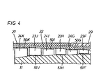
- the stator 10 comprises a tubular body or sleeve 22 carrying inwardly directed guide vanes 23 which are arranged in five axially spaced circumferential rows B, D, F, H, and J, whereas the rotor 11 is provided with drive blades 24 arranged in six axially spaced circumferential rows A, C, E, G, I, and K. See Fig 1.
- the drive blades 24 and the guide vanes 23 are disposed in alternating positions, viewed in the direction of the motive pressure air flow through the turbine. This means that between adjacent rows of drive blades 24 there is a row of guide vanes 23 for linking the pressure air flow into an optimum direction before entering the next row of drive blades 24.
- the reference numerals of the drive blades 24 and the guide vanes 23 are combined with the reference letters of the circumferential rows A, C, E, G, I, and K and B, D, F, H, and J, respectively, in which they are arranged.
- the stator 10 further comprises a forward mounting sleeve 27, forming an outer support for the sleeve 22, and a rear cup shaped nozzle piece 28.
- the latter has a forwardly directed tubular skirt portion 29 for radial support of the sleeve 22 and a rear air inlet portion 30.
- This portion is formed with an air inlet opening 31 communicating at its one end with the air inlet passage 19 and at its other end with radially directed air feed passages 32.
- These air feed passages 32 communicate motive pressure air from the inlet portion 30 to a number of air nozzles 33 by which the motive high speed air flow through the turbine is generated.
- the nozzle piece 28 also comprises a socket 34 forming a support for the rear rotor bearing 14.
- the stator 10 also comprises a ring element 35 which forms a radial as well as an axial support for the mounting sleeve 27.
- the ring element 35 is formed with a number of exhaust openings 36 communicating with the exhaust chamber 21.
- the motor turbine illustrated in the drawing figures is intended to be produced in small dimensions, i.e. having a rotor diameter from about 30 - 40 mm:s.
- the rotor drive blades 24 as well as the guide vanes 23 on the stator sleeve 22 are of such small sizes that it is not possible to produce them as separate details for mounting on the respective carrier.
- the drive blades 24 and the guide vanes 23 are machined out as integrated parts of the rotor 11 and the stator sleeve 22, respectively. Since the drive blades 24 are located on the outer surface of the rotor body 11, there is no problem to carry out the necessary machining work, for instance by a shank end mill.
- the latter is divided into three separate shells 22a, 22b and 22c. See Fig.2. These shells are divided along three cylinder generatrices located at 120 degrees intervals, which means that each shell has a circumferential extent of 120 degrees.
- the shells 22a, 22b and 22c are kept together in a fixed radial relationship by the forward mounting sleeve 27 and the tubular skirt portion 29 of the nozzle piece 28.
- the mounting sleeve 27 and the skirt portion 29 surround the shells 22a, 22b, 22c with a tight fit such that the positions of the shells 22a, 22b and 22c are accurately defined so as to form the tubular sleeve body 22.
- the stator shells 22a,22b and 22c are secured relative to the housing 12 by axial clamping between a shoulder 38 on the forward mounting sleeve 27 and a shoulder 39 on the nozzle piece skirt portion 29. The clamping force is obtained by the thread connection 18 between the two housing sections 16 and 17.
- a Belleville-type spring washer 37 which is disposed in the socket 34 behind the rear bearing 14 to ensure a correct axial load on the rotor bearings.
- FIG.3 there is illustrated machining situation wherein one of the stator shells 22a is firmly clamped against a part cylindrical surface of a fixture 40, and a milling spindle 41 fitted with a shank end mill 42 is in a position for machining a guide vane at the longitudinal edge of the shell.
- the shell is clamped in this position by means of screws 43, 44 and clamp rules 45, 46 carried on the fixture.
- This illustrated machining situation intends to show that machining of the guide vanes close to the edges of a stator shell would not be possible with a 180 degree two part divided stator.
- Each shell has to have a circumferential extent well below 180 degrees to give access to a machining tool.
- the extreme free ends of the drive blades 24 and guide vanes 23 form clearance seals with cylindrical surfaces 50 and 51 on the stator 10 and the rotor 11, respectively.
- the drive blades 24 in each circumferential row A, C, E, G, I, and K cooperate sealingly with a corresponding cylindrical surface 50 on the stator 10. It is to be noted that the drive blade and sealing surface reference numerals in Figs. 1 and 4 are provided with the suffix letter of the corresponding circumferential row.
- the circumferential extent of the stator shells does not have to be exactly the same.
- the guide vanes 23 are formed in one piece with and on the inside of the tubular stator body formed by the shells.
- the tubular body 22 has to be divided into three or more sections or shells each having a circumferential extent well below 180 degrees.
- stator shells 22a, 22b, 22c are fixed and mounted relative to each other by joints engaging external flanges located at the longitudinal edges of the shells. This method for fixing and mounting the stator shells is well known per se at bigger two-part turbine stators.
Landscapes
- Engineering & Computer Science (AREA)
- Mechanical Engineering (AREA)
- General Engineering & Computer Science (AREA)
- Turbine Rotor Nozzle Sealing (AREA)
Applications Claiming Priority (2)
| Application Number | Priority Date | Filing Date | Title |
|---|---|---|---|
| SE9603835A SE511813C2 (sv) | 1996-10-18 | 1996-10-18 | Axialflödesturbin |
| SE9603835 | 1996-10-18 |
Publications (3)
| Publication Number | Publication Date |
|---|---|
| EP0837223A2 EP0837223A2 (en) | 1998-04-22 |
| EP0837223A3 EP0837223A3 (en) | 2000-04-26 |
| EP0837223B1 true EP0837223B1 (en) | 2004-12-22 |
Family
ID=20404313
Family Applications (1)
| Application Number | Title | Priority Date | Filing Date |
|---|---|---|---|
| EP97850140A Expired - Lifetime EP0837223B1 (en) | 1996-10-18 | 1997-10-17 | Pneumatic axial flow turbine motor |
Country Status (5)
| Country | Link |
|---|---|
| US (1) | US6336790B1 (enExample) |
| EP (1) | EP0837223B1 (enExample) |
| JP (1) | JP4099250B2 (enExample) |
| DE (1) | DE69732010T2 (enExample) |
| SE (1) | SE511813C2 (enExample) |
Families Citing this family (10)
| Publication number | Priority date | Publication date | Assignee | Title |
|---|---|---|---|---|
| JP2007510155A (ja) | 2003-10-29 | 2007-04-19 | エージェンシー フォー サイエンス,テクノロジー アンド リサーチ | バイオセンサー |
| WO2007120066A1 (en) * | 2006-04-14 | 2007-10-25 | Gennady Mikhailovich Morgunov | The bladed machine (versions) |
| US8382426B2 (en) * | 2008-04-04 | 2013-02-26 | Koushi Itoh | High-speed air spindle |
| US8230607B2 (en) | 2008-05-09 | 2012-07-31 | Milwaukee Electric Tool Corporation | Keyless blade clamp for a power tool |
| DE102010013551B4 (de) * | 2010-03-31 | 2016-12-08 | Dürr Systems Ag | Turbinenrotor und Antriebsturbine für einen Rotationszerstäuber und Rotationszerstäuber |
| USD873874S1 (en) | 2012-09-28 | 2020-01-28 | Dürr Systems Ag | Axial turbine housing for a rotary atomizer for a painting robot |
| US10519805B2 (en) | 2015-04-13 | 2019-12-31 | United Technologies Corporation | Turbine case coupling |
| FR3037358B1 (fr) * | 2015-06-11 | 2017-05-19 | Snecma | Ensemble a carter d'echappement et piece aval de revolution |
| US10082042B2 (en) * | 2015-06-22 | 2018-09-25 | United Technologies Corporation | Case coupling and assembly |
| WO2025238386A1 (en) | 2024-05-13 | 2025-11-20 | Boskovic Nebojsa | Vane turbine machine |
Family Cites Families (22)
| Publication number | Priority date | Publication date | Assignee | Title |
|---|---|---|---|---|
| FR630558A (fr) * | 1926-03-08 | 1927-12-05 | Turbine à vapeur, à tambour à mouvement inverse | |
| FR633074A (fr) * | 1927-03-16 | 1928-01-20 | Oerlikon Maschf | Turbine à haute pression à vapeur ou à gaz |
| DE560836C (de) * | 1929-12-05 | 1932-10-07 | Wilhelm Seyerle Dr Ing | Axial beaufschlagte Turbine |
| DE732767C (de) * | 1940-05-21 | 1943-03-11 | Franz Karpinski Dipl Ing | Verfahren und Vorrichtung zur Herstellung von Turbinenraedern |
| US2565925A (en) * | 1946-04-10 | 1951-08-28 | Rolls Royce | Method of manufacturing guide vanes for axial flow turbines and compressors |
| US2638136A (en) * | 1948-05-13 | 1953-05-12 | Olen L Miller | Surface miller |
| US2633776A (en) * | 1948-08-14 | 1953-04-07 | Kellogg M W Co | Method of manufacturing turbine blades integral with turbine rotor |
| US3043559A (en) * | 1954-10-22 | 1962-07-10 | Maschf Augsburg Nuernberg Ag | Gas turbine |
| GB817957A (en) * | 1954-12-08 | 1959-08-06 | Kawasaki Heavy Ind Ltd | A steam turbine regulating stage |
| US2962941A (en) * | 1955-08-03 | 1960-12-06 | Avco Mfg Corp | Apparatus for producing a centrifugal compressor rotor |
| CH383734A (de) * | 1959-03-14 | 1964-10-31 | Svenska Rotor Maskiner Ab | Verfahren zur Herstellung eines Schaufelrades und nach dem Verfahren hergestelltes Schaufelrad |
| GB909058A (en) | 1961-06-28 | 1962-10-24 | Dana Corp | Improvements in or relating to turbine blading |
| US3241493A (en) * | 1964-05-04 | 1966-03-22 | Cascade Corp | Pump impeller |
| US3709630A (en) * | 1969-10-28 | 1973-01-09 | Howmet Int Inc | Pneumatic motor for medical instruments |
| BE788347A (fr) | 1971-09-20 | 1973-01-02 | Baxter Laboratories Inc | Trepan chirurgical pneumatique modulaire |
| SE406624B (sv) * | 1977-07-12 | 1979-02-19 | Stal Laval Turbin Ab | Turbomaskin |
| CH661678A5 (en) * | 1983-12-16 | 1987-08-14 | Starrfraesmaschinen Ag | Method for machining a shovel-shaped workpiece by a milling tool |
| US5180281A (en) * | 1990-09-12 | 1993-01-19 | United Technologies Corporation | Case tying means for gas turbine engine |
| GB2250782B (en) * | 1990-12-11 | 1994-04-27 | Rolls Royce Plc | Stator vane assembly |
| SE500743C2 (sv) | 1992-04-01 | 1994-08-22 | Abb Carbon Ab | Sätt och anordning för montering av axialströmningsmaskin |
| JP3631271B2 (ja) | 1993-11-19 | 2005-03-23 | ユナイテッド テクノロジーズ コーポレイション | インナーシュラウド一体型ステータベーン構造 |
| US5562404A (en) * | 1994-12-23 | 1996-10-08 | United Technologies Corporation | Vaned passage hub treatment for cantilever stator vanes |
-
1996
- 1996-10-18 SE SE9603835A patent/SE511813C2/sv not_active IP Right Cessation
-
1997
- 1997-10-17 JP JP28502697A patent/JP4099250B2/ja not_active Expired - Fee Related
- 1997-10-17 US US08/951,270 patent/US6336790B1/en not_active Expired - Fee Related
- 1997-10-17 EP EP97850140A patent/EP0837223B1/en not_active Expired - Lifetime
- 1997-10-17 DE DE69732010T patent/DE69732010T2/de not_active Expired - Lifetime
Also Published As
| Publication number | Publication date |
|---|---|
| DE69732010T2 (de) | 2006-03-02 |
| US6336790B1 (en) | 2002-01-08 |
| SE9603835D0 (sv) | 1996-10-18 |
| SE511813C2 (sv) | 1999-11-29 |
| SE9603835L (sv) | 1998-06-16 |
| JPH10212901A (ja) | 1998-08-11 |
| JP4099250B2 (ja) | 2008-06-11 |
| DE69732010D1 (de) | 2005-01-27 |
| EP0837223A3 (en) | 2000-04-26 |
| EP0837223A2 (en) | 1998-04-22 |
Similar Documents
| Publication | Publication Date | Title |
|---|---|---|
| EP0837223B1 (en) | Pneumatic axial flow turbine motor | |
| US8347500B2 (en) | Method of assembly and disassembly of a gas turbine mid turbine frame | |
| CA2672096C (en) | Fabricated itd-strut and vane ring for gas turbine engine | |
| US20120011824A1 (en) | Integral lubrication tube and nozzle combination | |
| US7704042B2 (en) | Turbomachine, especially a gas turbine | |
| JP2002526705A (ja) | セグメント化されたステータリング用のシール装置 | |
| GB2297871A (en) | Securing bearing in an electrical hand-held machine tool | |
| US9739150B2 (en) | Attaching the blades of an axial turbocompressor to the compressor drum | |
| US3937589A (en) | High pressure double flow turbine construction | |
| EP1744034B1 (en) | An arrangement for sealing a steam-cooled gas turbine | |
| US5142762A (en) | Air cycle machine alignment | |
| CN110773760B (zh) | 具有气密封严的双输出机械主轴机构 | |
| CN105324554B (zh) | 轴流膨胀机 | |
| EP1743089A1 (en) | Center housing of a turbine for a turbocharger and method of manufacturing the same | |
| US20140133976A1 (en) | Radial Fixing and Positioning Flanges for Shells of Axial Turbine Compressor Housings | |
| EP3862567B1 (en) | Apparatus for transferring pressurized fluid in a back-to-back multi-stage pump | |
| US10316667B2 (en) | Apparats for decreasing thrust of radial inflow turbine | |
| KR102222775B1 (ko) | 터렛 장치용 인덱싱 클램프 모듈 | |
| CN218934500U (zh) | 一种向心透平组件及向心透平发电装置 | |
| CN220101676U (zh) | 一种摇篮转台摆动轴结构以及机床 | |
| GB2558917A (en) | Zoned surface roughness | |
| US20070281273A1 (en) | Dental handpiece | |
| US10174644B2 (en) | Multipart rotor for a hydraulic camshaft adjuster with a supply of oil to the pressure chambers through the vanes | |
| CN116696484B (zh) | 一种向心透平组件及向心透平发电装置 | |
| US4960373A (en) | Fluid motor rotor assembly |
Legal Events
| Date | Code | Title | Description |
|---|---|---|---|
| PUAI | Public reference made under article 153(3) epc to a published international application that has entered the european phase |
Free format text: ORIGINAL CODE: 0009012 |
|
| AK | Designated contracting states |
Kind code of ref document: A2 Designated state(s): DE FR GB IT |
|
| AX | Request for extension of the european patent |
Free format text: AL;LT;LV;RO;SI |
|
| PUAL | Search report despatched |
Free format text: ORIGINAL CODE: 0009013 |
|
| AK | Designated contracting states |
Kind code of ref document: A3 Designated state(s): AT BE CH DE DK ES FI FR GB GR IE IT LI LU MC NL PT SE |
|
| AX | Request for extension of the european patent |
Free format text: AL;LT;LV;RO;SI |
|
| RIC1 | Information provided on ipc code assigned before grant |
Free format text: 7F 01D 15/06 A, 7F 01D 25/26 B, 7F 01D 9/04 B, 7F 01D 25/24 B |
|
| 17P | Request for examination filed |
Effective date: 20001011 |
|
| AKX | Designation fees paid |
Free format text: DE FR GB IT |
|
| 17Q | First examination report despatched |
Effective date: 20031222 |
|
| GRAP | Despatch of communication of intention to grant a patent |
Free format text: ORIGINAL CODE: EPIDOSNIGR1 |
|
| RTI1 | Title (correction) |
Free format text: PNEUMATIC AXIAL FLOW TURBINE MOTOR |
|
| GRAS | Grant fee paid |
Free format text: ORIGINAL CODE: EPIDOSNIGR3 |
|
| GRAA | (expected) grant |
Free format text: ORIGINAL CODE: 0009210 |
|
| AK | Designated contracting states |
Kind code of ref document: B1 Designated state(s): DE FR GB IT |
|
| REG | Reference to a national code |
Ref country code: GB Ref legal event code: FG4D |
|
| REF | Corresponds to: |
Ref document number: 69732010 Country of ref document: DE Date of ref document: 20050127 Kind code of ref document: P |
|
| PLBE | No opposition filed within time limit |
Free format text: ORIGINAL CODE: 0009261 |
|
| STAA | Information on the status of an ep patent application or granted ep patent |
Free format text: STATUS: NO OPPOSITION FILED WITHIN TIME LIMIT |
|
| 26N | No opposition filed |
Effective date: 20050923 |
|
| ET | Fr: translation filed | ||
| REG | Reference to a national code |
Ref country code: FR Ref legal event code: PLFP Year of fee payment: 19 |
|
| REG | Reference to a national code |
Ref country code: DE Ref legal event code: R082 Ref document number: 69732010 Country of ref document: DE Representative=s name: PATENTANWAELTE OLBRICHT, BUCHHOLD, KEULERTZ PA, DE |
|
| PGFP | Annual fee paid to national office [announced via postgrant information from national office to epo] |
Ref country code: GB Payment date: 20151027 Year of fee payment: 19 |
|
| REG | Reference to a national code |
Ref country code: FR Ref legal event code: PLFP Year of fee payment: 20 |
|
| PGFP | Annual fee paid to national office [announced via postgrant information from national office to epo] |
Ref country code: FR Payment date: 20161025 Year of fee payment: 20 Ref country code: DE Payment date: 20161027 Year of fee payment: 20 |
|
| PGFP | Annual fee paid to national office [announced via postgrant information from national office to epo] |
Ref country code: IT Payment date: 20161024 Year of fee payment: 20 |
|
| GBPC | Gb: european patent ceased through non-payment of renewal fee |
Effective date: 20161017 |
|
| PG25 | Lapsed in a contracting state [announced via postgrant information from national office to epo] |
Ref country code: GB Free format text: LAPSE BECAUSE OF NON-PAYMENT OF DUE FEES Effective date: 20161017 |
|
| REG | Reference to a national code |
Ref country code: DE Ref legal event code: R071 Ref document number: 69732010 Country of ref document: DE |