EP0836947B1 - Method and apparatus for drop weight encoding - Google Patents
Method and apparatus for drop weight encoding Download PDFInfo
- Publication number
- EP0836947B1 EP0836947B1 EP97307781A EP97307781A EP0836947B1 EP 0836947 B1 EP0836947 B1 EP 0836947B1 EP 97307781 A EP97307781 A EP 97307781A EP 97307781 A EP97307781 A EP 97307781A EP 0836947 B1 EP0836947 B1 EP 0836947B1
- Authority
- EP
- European Patent Office
- Prior art keywords
- inkjet
- printhead
- drop
- drop weight
- printer
- Prior art date
- Legal status (The legal status is an assumption and is not a legal conclusion. Google has not performed a legal analysis and makes no representation as to the accuracy of the status listed.)
- Expired - Lifetime
Links
- 238000000034 method Methods 0.000 title claims description 23
- 238000004519 manufacturing process Methods 0.000 claims description 30
- 238000003860 storage Methods 0.000 claims description 22
- 238000007641 inkjet printing Methods 0.000 claims 4
- 238000009826 distribution Methods 0.000 description 11
- 238000010438 heat treatment Methods 0.000 description 5
- 238000004891 communication Methods 0.000 description 4
- 239000012530 fluid Substances 0.000 description 4
- RYGMFSIKBFXOCR-UHFFFAOYSA-N Copper Chemical compound [Cu] RYGMFSIKBFXOCR-UHFFFAOYSA-N 0.000 description 3
- 239000003086 colorant Substances 0.000 description 3
- 229910052802 copper Inorganic materials 0.000 description 3
- 239000010949 copper Substances 0.000 description 3
- 238000010304 firing Methods 0.000 description 3
- 230000003213 activating effect Effects 0.000 description 2
- 239000004020 conductor Substances 0.000 description 2
- 238000005315 distribution function Methods 0.000 description 2
- 230000006870 function Effects 0.000 description 2
- 239000004593 Epoxy Substances 0.000 description 1
- 230000015572 biosynthetic process Effects 0.000 description 1
- 230000000694 effects Effects 0.000 description 1
- 238000005530 etching Methods 0.000 description 1
- 238000005259 measurement Methods 0.000 description 1
- 238000012544 monitoring process Methods 0.000 description 1
- 229920001721 polyimide Polymers 0.000 description 1
- 239000002861 polymer material Substances 0.000 description 1
- 238000013179 statistical model Methods 0.000 description 1
- 239000000126 substance Substances 0.000 description 1
- 239000002699 waste material Substances 0.000 description 1
- 238000005303 weighing Methods 0.000 description 1
Images

Classifications
-
- B—PERFORMING OPERATIONS; TRANSPORTING
- B41—PRINTING; LINING MACHINES; TYPEWRITERS; STAMPS
- B41J—TYPEWRITERS; SELECTIVE PRINTING MECHANISMS, i.e. MECHANISMS PRINTING OTHERWISE THAN FROM A FORME; CORRECTION OF TYPOGRAPHICAL ERRORS
- B41J2/00—Typewriters or selective printing mechanisms characterised by the printing or marking process for which they are designed
- B41J2/005—Typewriters or selective printing mechanisms characterised by the printing or marking process for which they are designed characterised by bringing liquid or particles selectively into contact with a printing material
- B41J2/01—Ink jet
- B41J2/17—Ink jet characterised by ink handling
- B41J2/175—Ink supply systems ; Circuit parts therefor
- B41J2/17503—Ink cartridges
- B41J2/17543—Cartridge presence detection or type identification
- B41J2/17546—Cartridge presence detection or type identification electronically
-
- B—PERFORMING OPERATIONS; TRANSPORTING
- B41—PRINTING; LINING MACHINES; TYPEWRITERS; STAMPS
- B41J—TYPEWRITERS; SELECTIVE PRINTING MECHANISMS, i.e. MECHANISMS PRINTING OTHERWISE THAN FROM A FORME; CORRECTION OF TYPOGRAPHICAL ERRORS
- B41J2/00—Typewriters or selective printing mechanisms characterised by the printing or marking process for which they are designed
- B41J2/005—Typewriters or selective printing mechanisms characterised by the printing or marking process for which they are designed characterised by bringing liquid or particles selectively into contact with a printing material
- B41J2/01—Ink jet
- B41J2/015—Ink jet characterised by the jet generation process
- B41J2/04—Ink jet characterised by the jet generation process generating single droplets or particles on demand
- B41J2/045—Ink jet characterised by the jet generation process generating single droplets or particles on demand by pressure, e.g. electromechanical transducers
- B41J2/04501—Control methods or devices therefor, e.g. driver circuits, control circuits
- B41J2/0456—Control methods or devices therefor, e.g. driver circuits, control circuits detecting drop size, volume or weight
-
- B—PERFORMING OPERATIONS; TRANSPORTING
- B41—PRINTING; LINING MACHINES; TYPEWRITERS; STAMPS
- B41J—TYPEWRITERS; SELECTIVE PRINTING MECHANISMS, i.e. MECHANISMS PRINTING OTHERWISE THAN FROM A FORME; CORRECTION OF TYPOGRAPHICAL ERRORS
- B41J2/00—Typewriters or selective printing mechanisms characterised by the printing or marking process for which they are designed
- B41J2/005—Typewriters or selective printing mechanisms characterised by the printing or marking process for which they are designed characterised by bringing liquid or particles selectively into contact with a printing material
- B41J2/01—Ink jet
- B41J2/015—Ink jet characterised by the jet generation process
- B41J2/04—Ink jet characterised by the jet generation process generating single droplets or particles on demand
- B41J2/045—Ink jet characterised by the jet generation process generating single droplets or particles on demand by pressure, e.g. electromechanical transducers
- B41J2/04501—Control methods or devices therefor, e.g. driver circuits, control circuits
- B41J2/04586—Control methods or devices therefor, e.g. driver circuits, control circuits controlling heads of a type not covered by groups B41J2/04575 - B41J2/04585, or of an undefined type
-
- B—PERFORMING OPERATIONS; TRANSPORTING
- B41—PRINTING; LINING MACHINES; TYPEWRITERS; STAMPS
- B41J—TYPEWRITERS; SELECTIVE PRINTING MECHANISMS, i.e. MECHANISMS PRINTING OTHERWISE THAN FROM A FORME; CORRECTION OF TYPOGRAPHICAL ERRORS
- B41J2/00—Typewriters or selective printing mechanisms characterised by the printing or marking process for which they are designed
- B41J2/005—Typewriters or selective printing mechanisms characterised by the printing or marking process for which they are designed characterised by bringing liquid or particles selectively into contact with a printing material
- B41J2/01—Ink jet
- B41J2/21—Ink jet for multi-colour printing
- B41J2/2121—Ink jet for multi-colour printing characterised by dot size, e.g. combinations of printed dots of different diameter
- B41J2/2128—Ink jet for multi-colour printing characterised by dot size, e.g. combinations of printed dots of different diameter by means of energy modulation
Definitions
- the present invention relates to inkjet printers. More particularly, the present invention relates to a technique for encoding drop weight for a particular printhead using resistance values thereby allowing the printer to compensate for manufacturing tolerances of the printhead.
- Thermal inkjet printers operate by rapidly heating a small volume of ink and causing the ink to vaporize, thereby ejecting a droplet of ink through an orifice to strike a recording medium, such as a sheet of paper.
- a recording medium such as a sheet of paper.
- the printhead typically includes an orifice plate having very small nozzles through which the ink droplets are ejected. Adjacent to the nozzles inside the printhead are ink chambers, where ink is stored prior to ejection. Ink is delivered to the ink chambers through ink channels that are in fluid communication with an ink supply.
- the ink supply may be contained in a reservoir proximate the printhead or in the case of "off-axis" printers, the ink supply may be spaced from the printhead.
- Ejection of an ink droplet through a nozzle may be accomplished by quickly heating a volume of ink within the ink chamber. Rapid expansion of ink vapor forces ink within the chamber through the corresponding nozzle forming a droplet. This process is called "firing".
- the ink in the chamber is heated with a heat transducer that is aligned with the corresponding nozzle.
- the heat transducer is a resistor, or piezoelectric transducer, but may comprise any substance or device capable of quickly heating the ink.
- the inkjet printhead is often mounted in a print cartridge which contains some form of ink reservoir portion.
- manufacturing tolerances tend to result in variation in drop volume from one printhead to next.
- This drop volume variation results from manufacturing tolerances in orifice diameter, the heating element formation such as resistor size in the case of a resistive heating element, the ink chamber size, and the ink channel dimensions, to name a few.
- manufacturing tolerances all tend to produce variations in ink drop volume from one printhead to the next.
- Some printers use techniques such as drop counting to determine an amount of ink remaining. As a result of drop volume variation, it is difficult to determine the amount of ink remaining in the ink cartridge or external ink supply. Therefore, manufacturing tolerances resulting in drop volume variation make drop counting techniques less reliable.
- this drop volume variation affects the output image quality formed on print media.
- the drops that are ejected onto the print media form small dots on the print media.
- the drop volume variation tends to result in dot size variation resulting in poor dot overlap. Poor dot overlap in text images results in poor print quality.
- images which are formed having varying intensities sometimes referred to as "grayscale images" the color intensity or hue is related to the dot density. For example, in color printing frequently cyan, magenta and yellow drops of ink are used to produce a gamut of colors. Drop weight variation among different colors alters the dot size and therefore alters dot coverage which significantly affects the color reproduction. For example, if the magenta drop volume is significantly higher than intended, a hue shift will result in the output image which seriously reduces the printed image quality.
- US-A-5 289 210 describes an image recording apparatus in which the unevenness in density in each recording head is measured during production thereof and data indicative of the density unevenness or data for correcting the density unevenness are stored in an EEPROM for respective discharge openings or for respective groups each including a certain number of such openings. The data are subsequently read by a printing device during a printing operation so as to effect a control operation for reducing the density unevenness.
- US-A-5 387 976 describes a method for measuring drop volume in an inkjet printhead by printing samples comprised of multiple drops of ink on a recording medium. A system for automatically self-correcting for drop volume is also described.
- an inkjet print cartridge as defined in claim 1.
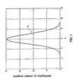
- FIG 1 depicts a drop weight distribution curve for printheads having a nominal drop weight of 6 nanograms.
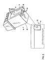
- FIG 2 depicts a print cartridge of the present invention which includes an apparatus for encoding drop weight for the particular printhead.
- FIG 3 depicts the preferred embodiment of the present invention for encoding drop weight using a resistive network.
- FIG 1 depicts a normal or Gaussian distribution curve 9 for an inkjet printhead that is produced in a manufacturing environment.
- the normal distribution curve 9 tends to be representative of inkjet printheads which are formed in high volume using numerous manufacturing steps with each step having a manufacturing tolerance associated therewith.
- the distribution curve 9 of FIG 1 represents a manufacturing process for forming inkjet printheads having a nominal drop weight of 6 nanograms.
- the distribution curve 9 has an x-axis representing drop weight in nanograms and a y-axis representing the distribution function for printheads having a mean (cmean) equal to 6 nanograms and a standard deviation (csigma) equal to 1 nanogram. Therefore, the y-axis is representative of a percentage of printheads having a drop weight shown on the x-axis.
- printhead manufacturing tolerances can be represented by the normal distribution shown in FIG 1.
- the normal distribution for a 6 nanogram printhead is shown for illustrative purposes, printheads may have different nominal drop weights or different standard deviations.
- the actual distribution curve may be differ from the normal distribution curve 9 depending on the particular manufacturing methods used.
- the drop volume and drop weight are related. Because it tends to be easier to measure drop weight than drop volume the method and apparatus of the present invention utilizes drop weight information. However, the method and apparatus is equally applicable to drop volume information as well.
- the area under this curve 9 represents the number of printheads having a given drop weight range. Therefore, using this distribution 68.3 percent of the printheads are within 1 sigma or 1 nanogram of the nominal, 6 nanograms, 95.6 percent are within the 2 sigma range and 99.7 percent are within the 3 sigma range.
- Some of the printheads will have drop weights of +/- 3 sigma which corresponds to drop weights of 3 nanograms and 9 nanograms. These 3 and 9 nanogram printheads have a drop weight variation that is 50% from the mean of 6 nanograms. Therefore, if printer parameters are chosen for the nominal drop weight of 6 nanograms for instance, then some printheads will be used which will have drop weights of 3 and 9 nanograms toward the outer edge of the manufacturing range. It is likely that this manufacturing tolerance will result in performance problems such as dot overlap problems on the print medium. The variation in print overlap due to drop weight variation tends to reduce the quality of the output image. In addition, printers which use drop counting techniques for monitoring ink consumption may be off by as much as 50% due to this drop weight variation of the printhead.
- the printheads are sorted and only the printheads having a drop weight variation of one sigma from the nominal are used then this would be 68.3 percent of the printheads. The remaining 31.7 percent of the printheads would be unusable resulting in waste as well as increased manufacturing costs.
- FIG 2 depicts a preferred embodiment of the inkjet print cartridge 10 of the present invention for use in the inkjet printer 12 for forming images on print medium.
- the inkjet printer 12 including a cartridge mount 13 for receiving one or more inkjet print cartridges 10.
- the inkjet print cartridge 10 includes an inkjet printhead 14 that is responsive to print control signals for ejecting ink drops onto print media.
- the inkjet printhead 14 has a manufacturing tolerance associated therewith producing a range of drop weights.
- the inkjet printhead 14 has a corresponding drop weight from the range of drop weights.
- the inkjet print cartridge 10 includes an information storage device 16 that is associated with the inkjet printhead 14 for storing information for identifying the corresponding drop weight.
- the inkjet print cartridge 10 includes a pen body which defines a reservoir 18.
- the reservoir 18 is configured to hold a quantity of ink.
- the printhead 14 is fit to the bottom 20 of the print cartridge 10 and is controlled by electrical interconnects 21 for ejecting ink droplets from the printhead 14.
- the printhead 14 defines a set of nozzles 22 for expelling ink, in a controlled pattern, during printing. Each nozzle 22 is in fluid communication with a firing chamber (not shown) that is defined within the printhead 14.
- the print cartridge 10 includes an ink supply within the cartridge reservoir 18.
- the ink cartridge 10 may be configured for use with (off-axis) ink supplies which are spaced from the print cartridge 10 and in fluid communication with the print cartridge 10.
- a supply conduit (not shown) conducts ink from the ink reservoir 18 to one or more ink channels (not shown) defined within the print cartridge 10.
- the ink channels are configured so that ink moving therethrough is in fluid communication with each of the firing chambers and hence each nozzle 22.
- the information storage device 16 in the preferred embodiment is a circuit connected between a pair of terminals 24 and 26.
- the circuit provides a resistance between the terminals 24 and 26 which is indicative of the drop weight of the particular printhead 14.
- a series of switches 28 are provided for selecting a resistance value for the circuit between terminals 24 and 26 for identifying the drop weight of the printhead 14.
- FIG 3 depicts the preferred embodiment of the storage device 16 for identifying the drop weight of the printhead 14.
- the storage device 16 includes a plurality of resistors 30 connected in parallel between terminals 24 and 26. Connected in series with each of the resistors 30 are switches 28. The resistance between terminals 24 and 26 are selected by selectively activating switches 28. Once the drop weight of the printhead 14 is determined, the appropriate switches 28 are activated to selected a resistance value corresponding to the drop weight of the printhead 14.
- An information retrieval device 32 having a pair of terminals 34 and 36 are configured for engaging the corresponding terminals 24 and 26, respectively of the storage device 16 for retrieving the drop weight of the printhead 14 from the storage device 16.
- the information retrieval device 32 is a resistance sense circuit that is located on the printer 12.
- the terminals 34 and 36 are positioned such that when the ink cartridge 10 is properly installed in the printer 12 the terminals 34 and 36 of the information retrieval device 32 are electrically connected to the terminals 24 and 26 of the storage device 16 so that the drop weight information stored in the storage device 16 can be retrieved by the information retrieval device 32 so that the printer 12 can properly compensate for any drop weight variation by the printhead 14.
- the storage device 16 in the preferred embodiment, makes use of resistors 30 which have either the same or nearly the same resistance value.
- resistors 30 which have either the same or nearly the same resistance value.
- the total value of the resistance for the storage device 16 circuit is equal to R t where the circuit has n resistors with each resistor has a resistance value of R.
- a resistance value is preassigned for each group of drop weights of interest for the printhead 14. Once the printhead 14 or print cartridge 10 is inserted into the printer 12, the resistance is measured by the information retrieval device 32 of the printer 12 for determining ink usage as well as ink coverage for improving the quality and reliability of the printer 12.
- the storage device 16 is formed by a conductive layer such as copper on an insulating layer such a polymer material such as polyimid.
- the conductive portions are preferably defined using a photolithographic technique and an etching technique.
- the switches 28 are formed by defining a gap or spacing in the copper conductive traces thereby setting each of the switches 28 to an inactive mode or nonconductive mode. Once the drop weight is determined for the printhead 14, the switches 28 are selectively activated by selectively placing an electrically conductive material between the gaps or spacing in the conductive traces thereby electrically connecting the selected resistor between the pair of terminals 24 and 26.
- the conductive material is a conductive epoxy is placed between the gaps or spacing for electrically connect the copper traces thereby activating the switch 28.
- the conductive material is a conductive epoxy is placed between the gaps or spacing for electrically connect the copper traces thereby activating the switch 28.
- the number of switches 28 which are activated is related to the drop weight of the printhead 14.
- the drop weight of the printhead 14 is determined either directly or indirectly.
- the direct method for determining the drop weight of the printhead 14 is to fire or eject a known number of drops into a collection pan in a weighing scale. The weight is recorded and the average drop weight can then be determined.
- the indirect method for determining the drop weight for printhead 14 is by printing a pattern of dots on a medium. The drop weight can then be inferred by spot size. Spot size may be measured using machine vision in the preferred embodiment. The drop weight is then calculated from the spot size based on experimental correlation which is stored in a computer. Based on the data of drop weight, printheads can then be sorted according to ranges of drop weight.
- the 3-9 nanogram drop weight range as disclosed in FIG 1 may be subdivided into 3 groups each group consisting of a 1.5 nanogram range.
- a code is then used to activate or program switches 28 such that when the cartridge 10 is inserted into the printer 12 the printer 12 properly compensates for the drop weight of the particular printhead 14.
- printhead parameters such as resistor, orifice, chamber dimensions etc. can be related by a statistical model correlation equation to drop weight based on experimental measurements of drop weight and printhead parameters. For a given printhead knowing the critical dimensions, a drop weight can be calculated based on model equation and the pen can be encoded with this drop weight using the apparatus of the present invention.
- the storage device 16 has been described as a resistor array which has a resistance value that is selectable or programmable.
- the storage device 16 can be a variety of devices for storing information indicative of drop weight for the printhead.
- the storage device 16 can be a plurality of capacitive elements that are configured to provide a known capacitive value representative of drop weight.
- the information retrieval device 32 is capable of determining the drop weight based on the capacitance value.
- the storage device 16 can be a label having an indicia indicative of drop weight. The label is affixed to the print cartridge 10 once the drop weight is determined.
- the information retrieval device 32 within printer 12 is a label reading device for determining the printhead drop weight.
- the storage device 16 is some form of electronic memory such as a read only memory (ROM), read access memory (RAM) or some form of programmable device such as electrically erasable read only memory (EEPROM) for storing drop weight information.
- ROM read only memory
- RAM read access memory
- EEPROM electrically erasable read only memory
- the information retrieval device 32 within printer 12 for these examples is a suitable device for reading drop weight information from these devices.
- the present invention provides a low cost technique for identifying or tagging printheads by drop weight.
- drop weights for each of the colors can be encoded or identified by the printhead.
- the printer which these printheads are installed are capable of reading these tags or drop weight information, thus allowing the printer to compensate for drop weight variation from printhead to printhead.
- the printer is capable of forming high quality output images using printheads having a wide range of drop weights. Because printheads having a wider range of drop weights can be used the manufacturing costs of the printhead is reduced.
Landscapes
- Ink Jet (AREA)
- Particle Formation And Scattering Control In Inkjet Printers (AREA)
Applications Claiming Priority (2)
| Application Number | Priority Date | Filing Date | Title |
|---|---|---|---|
| US08/732,864 US6655775B1 (en) | 1996-10-15 | 1996-10-15 | Method and apparatus for drop weight encoding |
| US732864 | 2000-12-11 |
Publications (3)
| Publication Number | Publication Date |
|---|---|
| EP0836947A2 EP0836947A2 (en) | 1998-04-22 |
| EP0836947A3 EP0836947A3 (en) | 1999-09-01 |
| EP0836947B1 true EP0836947B1 (en) | 2004-03-24 |
Family
ID=24945253
Family Applications (1)
| Application Number | Title | Priority Date | Filing Date |
|---|---|---|---|
| EP97307781A Expired - Lifetime EP0836947B1 (en) | 1996-10-15 | 1997-10-02 | Method and apparatus for drop weight encoding |
Country Status (4)
| Country | Link |
|---|---|
| US (1) | US6655775B1 (enExample) |
| EP (1) | EP0836947B1 (enExample) |
| JP (1) | JP4213774B2 (enExample) |
| DE (1) | DE69728229T2 (enExample) |
Families Citing this family (12)
| Publication number | Priority date | Publication date | Assignee | Title |
|---|---|---|---|---|
| US6585340B1 (en) * | 1998-09-03 | 2003-07-01 | Hewlett-Packard Development Company, L.P. | Environmental and operational color calibration, with integrated ink limiting, in incremental printing |
| US20010035964A1 (en) * | 2000-04-20 | 2001-11-01 | Hiroyasu Kurashina | Tape cartridge, tape printing method, tape printing apparatus, and label-producing method |
| US7121642B2 (en) * | 2002-08-07 | 2006-10-17 | Osram Opto Semiconductors Gmbh | Drop volume measurement and control for ink jet printing |
| US7568779B2 (en) | 2003-02-10 | 2009-08-04 | Canon Kabushiki Kaisha | Liquid applicator and liquid supply method to be used in liquid applicator |
| US7249815B2 (en) * | 2004-01-30 | 2007-07-31 | Hewlett-Packard Development Company, L.P. | Nozzle distribution |
| FR2881066B1 (fr) * | 2005-01-25 | 2007-10-26 | Hewlett Packard Development Co | Repartition de buses |
| JP2007152340A (ja) * | 2005-11-11 | 2007-06-21 | Seiko Epson Corp | 吐出量測定方法、パターン形成方法、デバイス、電気光学装置、電子機器 |
| DE102008030955B3 (de) | 2008-07-02 | 2009-11-19 | Hülsta-Werke Hüls Gmbh & Co. Kg | Verwendung eines mit einem Dekor bedruckten Druckpapiers für flächige Bauteile |
| US9096056B2 (en) * | 2011-05-19 | 2015-08-04 | Xerox Corporation | Apparatus and method for measuring drop volume |
| US10214019B2 (en) | 2012-04-30 | 2019-02-26 | Hewlett-Packard Development Company, L.P. | Flexible substrate with integrated circuit |
| CN104943395B (zh) * | 2014-11-28 | 2016-08-31 | 珠海艾派克微电子有限公司 | 一种操作指令生成电路和耗材芯片 |
| CN113524913B (zh) * | 2020-04-18 | 2022-10-21 | 深圳市汉森软件有限公司 | 墨水授权使用方法、服务端、上位机、打印设备及系统 |
Family Cites Families (20)
| Publication number | Priority date | Publication date | Assignee | Title |
|---|---|---|---|---|
| FR2566327B1 (fr) | 1984-06-25 | 1989-06-02 | Epson Corp | Imprimante |
| US5039237A (en) * | 1987-06-02 | 1991-08-13 | Oki Electric Industry Co., Ltd. | Dot matrix print head drive method |
| DE3730110A1 (de) | 1987-09-08 | 1989-03-16 | Siemens Ag | Druckeinrichtung mit einem elektrothermisch betriebenen druckkopf |
| US4872027A (en) | 1987-11-03 | 1989-10-03 | Hewlett-Packard Company | Printer having identifiable interchangeable heads |
| US5033887A (en) | 1988-07-25 | 1991-07-23 | Nixdorf Computer Ag | Process for the production of information relative to the type of a printing head |
| US5049898A (en) | 1989-03-20 | 1991-09-17 | Hewlett-Packard Company | Printhead having memory element |
| US5107276A (en) | 1989-07-03 | 1992-04-21 | Xerox Corporation | Thermal ink jet printhead with constant operating temperature |
| DE69034019T2 (de) | 1989-08-05 | 2003-10-09 | Canon K.K., Tokio/Tokyo | Tintenkassette |
| US5072235A (en) | 1990-06-26 | 1991-12-10 | Xerox Corporation | Method and apparatus for the electronic detection of air inside a thermal inkjet printhead |
| JP2915583B2 (ja) | 1991-01-14 | 1999-07-05 | キヤノン株式会社 | 画像記録装置 |
| DE69232448T2 (de) | 1991-07-30 | 2002-08-14 | Canon K.K., Tokio/Tokyo | Apparat und Verfahren zum Tintenstrahldrucken |
| US5504507A (en) * | 1992-10-08 | 1996-04-02 | Xerox Corporation | Electronically readable performance data on a thermal ink jet printhead chip |
| JPH06336070A (ja) | 1993-05-27 | 1994-12-06 | Tokyo Electric Co Ltd | プリンタユニット及びプリンタ装置 |
| EP0626266B1 (en) | 1993-05-27 | 2002-03-13 | Canon Kabushiki Kaisha | Recording apparatus controlled with head characteristics and recording method |
| US5387976A (en) | 1993-10-29 | 1995-02-07 | Hewlett-Packard Company | Method and system for measuring drop-volume in ink-jet printers |
| JPH07248250A (ja) | 1994-03-09 | 1995-09-26 | Brother Ind Ltd | 微小液滴重量測定装置 |
| AU3241795A (en) * | 1994-08-09 | 1996-03-07 | Encad, Inc. | Printer ink cartridge |
| US5610635A (en) | 1994-08-09 | 1997-03-11 | Encad, Inc. | Printer ink cartridge with memory storage capacity |
| US5699091A (en) * | 1994-12-22 | 1997-12-16 | Hewlett-Packard Company | Replaceable part with integral memory for usage, calibration and other data |
| US5812156A (en) | 1997-01-21 | 1998-09-22 | Hewlett-Packard Company | Apparatus controlled by data from consumable parts with incorporated memory devices |
-
1996
- 1996-10-15 US US08/732,864 patent/US6655775B1/en not_active Expired - Lifetime
-
1997
- 1997-09-29 JP JP26430797A patent/JP4213774B2/ja not_active Expired - Fee Related
- 1997-10-02 EP EP97307781A patent/EP0836947B1/en not_active Expired - Lifetime
- 1997-10-02 DE DE69728229T patent/DE69728229T2/de not_active Expired - Lifetime
Also Published As
| Publication number | Publication date |
|---|---|
| JP4213774B2 (ja) | 2009-01-21 |
| DE69728229D1 (de) | 2004-04-29 |
| DE69728229T2 (de) | 2005-02-24 |
| EP0836947A2 (en) | 1998-04-22 |
| EP0836947A3 (en) | 1999-09-01 |
| JPH10119315A (ja) | 1998-05-12 |
| US6655775B1 (en) | 2003-12-02 |
Similar Documents
| Publication | Publication Date | Title |
|---|---|---|
| KR101787183B1 (ko) | 인증 시스템 및 방법 | |
| US6315381B1 (en) | Energy control method for an inkjet print cartridge | |
| EP0836947B1 (en) | Method and apparatus for drop weight encoding | |
| EP0650837B1 (en) | Energy management scheme for an ink-jet printer | |
| KR100688009B1 (ko) | 오리피스 플레이트, 개선된 열 잉크젯 프린트헤드, 강한 버블 이동의 제공 방법, 잉크젯 프린터 및 잉크 컨테이너/카트리지 | |
| US5576745A (en) | Recording apparatus having thermal head and recording method | |
| US5497174A (en) | Voltage drop correction for ink jet printer | |
| US5504507A (en) | Electronically readable performance data on a thermal ink jet printhead chip | |
| EP0709192B1 (en) | Method and apparatus for correcting printhead, printhead corrected by this apparatus, and printing apparatus using this printhead | |
| US6866359B2 (en) | Ink jet printhead quality management system and method | |
| JPH1016230A (ja) | プリントヘッドおよびプリント装置 | |
| US20020012020A1 (en) | Method and apparatus for ink-jet drop trajectory and alignment error detection and correction | |
| EP1957278B1 (en) | Ink jet recording head, ink jet cartridge with ink jet recording head, and ink jet recording apparatus | |
| JPH04232753A (ja) | サーマルインクジェットプリンタ、不破壊気泡の検出装置及び方法 | |
| US6464320B1 (en) | Recording head and recording apparatus using the same | |
| CA2108302C (en) | Ink jet recording apparatus | |
| MXPA03009579A (es) | Diseno de resistencia para impresora de chorro de tinta termica tolerante a defectos. | |
| JPH10119315A5 (enExample) | ||
| US6513901B1 (en) | Method and apparatus for determining drop volume from a drop ejection device | |
| EP1561579B1 (en) | Method for identifying a fluid ejection device, controller and fluid ejection device therefor | |
| JP3420268B2 (ja) | インクジェット装置 | |
| EP0622209B1 (en) | Method for detecting and correcting an intrusion of air into a printhead substrate of an ink jet cartridge | |
| US6050665A (en) | Printing device with function for advising control unit of rank of mounted print head | |
| US6364445B1 (en) | Image printing apparatus and method | |
| US12030310B2 (en) | Maintenance routines |
Legal Events
| Date | Code | Title | Description |
|---|---|---|---|
| PUAI | Public reference made under article 153(3) epc to a published international application that has entered the european phase |
Free format text: ORIGINAL CODE: 0009012 |
|
| AK | Designated contracting states |
Kind code of ref document: A2 Designated state(s): DE FR GB IT |
|
| AX | Request for extension of the european patent |
Free format text: AL;LT;LV;RO;SI |
|
| PUAL | Search report despatched |
Free format text: ORIGINAL CODE: 0009013 |
|
| AK | Designated contracting states |
Kind code of ref document: A3 Designated state(s): AT BE CH DE DK ES FI FR GB GR IE IT LI LU MC NL PT SE |
|
| AX | Request for extension of the european patent |
Free format text: AL;LT;LV;RO;SI |
|
| RIC1 | Information provided on ipc code assigned before grant |
Free format text: 6B 41J 2/21 A, 6B 41J 25/34 B, 6B 41J 2/175 B, 6B 41J 2/16 B |
|
| 17P | Request for examination filed |
Effective date: 20000208 |
|
| AKX | Designation fees paid |
Free format text: DE FR GB IT |
|
| RAP1 | Party data changed (applicant data changed or rights of an application transferred) |
Owner name: HEWLETT-PACKARD COMPANY, A DELAWARE CORPORATION |
|
| 17Q | First examination report despatched |
Effective date: 20021216 |
|
| GRAP | Despatch of communication of intention to grant a patent |
Free format text: ORIGINAL CODE: EPIDOSNIGR1 |
|
| GRAS | Grant fee paid |
Free format text: ORIGINAL CODE: EPIDOSNIGR3 |
|
| GRAA | (expected) grant |
Free format text: ORIGINAL CODE: 0009210 |
|
| AK | Designated contracting states |
Kind code of ref document: B1 Designated state(s): DE FR GB IT |
|
| REG | Reference to a national code |
Ref country code: GB Ref legal event code: FG4D |
|
| REF | Corresponds to: |
Ref document number: 69728229 Country of ref document: DE Date of ref document: 20040429 Kind code of ref document: P |
|
| ET | Fr: translation filed | ||
| PLBE | No opposition filed within time limit |
Free format text: ORIGINAL CODE: 0009261 |
|
| STAA | Information on the status of an ep patent application or granted ep patent |
Free format text: STATUS: NO OPPOSITION FILED WITHIN TIME LIMIT |
|
| 26N | No opposition filed |
Effective date: 20041228 |
|
| REG | Reference to a national code |
Ref country code: GB Ref legal event code: 732E Free format text: REGISTERED BETWEEN 20120329 AND 20120404 |
|
| REG | Reference to a national code |
Ref country code: FR Ref legal event code: PLFP Year of fee payment: 19 |
|
| PGFP | Annual fee paid to national office [announced via postgrant information from national office to epo] |
Ref country code: GB Payment date: 20150924 Year of fee payment: 19 |
|
| PGFP | Annual fee paid to national office [announced via postgrant information from national office to epo] |
Ref country code: FR Payment date: 20150925 Year of fee payment: 19 |
|
| PGFP | Annual fee paid to national office [announced via postgrant information from national office to epo] |
Ref country code: IT Payment date: 20150925 Year of fee payment: 19 Ref country code: DE Payment date: 20150922 Year of fee payment: 19 |
|
| REG | Reference to a national code |
Ref country code: DE Ref legal event code: R119 Ref document number: 69728229 Country of ref document: DE |
|
| GBPC | Gb: european patent ceased through non-payment of renewal fee |
Effective date: 20161002 |
|
| REG | Reference to a national code |
Ref country code: FR Ref legal event code: ST Effective date: 20170630 |
|
| PG25 | Lapsed in a contracting state [announced via postgrant information from national office to epo] |
Ref country code: FR Free format text: LAPSE BECAUSE OF NON-PAYMENT OF DUE FEES Effective date: 20161102 Ref country code: GB Free format text: LAPSE BECAUSE OF NON-PAYMENT OF DUE FEES Effective date: 20161002 Ref country code: DE Free format text: LAPSE BECAUSE OF NON-PAYMENT OF DUE FEES Effective date: 20170503 |
|
| PG25 | Lapsed in a contracting state [announced via postgrant information from national office to epo] |
Ref country code: IT Free format text: LAPSE BECAUSE OF NON-PAYMENT OF DUE FEES Effective date: 20161002 |