EP0835992B1 - Propulsion unit, especially for a motor vehicle - Google Patents
Propulsion unit, especially for a motor vehicle Download PDFInfo
- Publication number
- EP0835992B1 EP0835992B1 EP97116123A EP97116123A EP0835992B1 EP 0835992 B1 EP0835992 B1 EP 0835992B1 EP 97116123 A EP97116123 A EP 97116123A EP 97116123 A EP97116123 A EP 97116123A EP 0835992 B1 EP0835992 B1 EP 0835992B1
- Authority
- EP
- European Patent Office
- Prior art keywords
- torsional vibration
- vibration damper
- drive unit
- motor vehicle
- cooling circuit
- Prior art date
- Legal status (The legal status is an assumption and is not a legal conclusion. Google has not performed a legal analysis and makes no representation as to the accuracy of the status listed.)
- Expired - Lifetime
Links
Images

Classifications
-
- F—MECHANICAL ENGINEERING; LIGHTING; HEATING; WEAPONS; BLASTING
- F01—MACHINES OR ENGINES IN GENERAL; ENGINE PLANTS IN GENERAL; STEAM ENGINES
- F01P—COOLING OF MACHINES OR ENGINES IN GENERAL; COOLING OF INTERNAL-COMBUSTION ENGINES
- F01P5/00—Pumping cooling-air or liquid coolants
- F01P5/10—Pumping liquid coolant; Arrangements of coolant pumps
-
- B—PERFORMING OPERATIONS; TRANSPORTING
- B60—VEHICLES IN GENERAL
- B60K—ARRANGEMENT OR MOUNTING OF PROPULSION UNITS OR OF TRANSMISSIONS IN VEHICLES; ARRANGEMENT OR MOUNTING OF PLURAL DIVERSE PRIME-MOVERS IN VEHICLES; AUXILIARY DRIVES FOR VEHICLES; INSTRUMENTATION OR DASHBOARDS FOR VEHICLES; ARRANGEMENTS IN CONNECTION WITH COOLING, AIR INTAKE, GAS EXHAUST OR FUEL SUPPLY OF PROPULSION UNITS IN VEHICLES
- B60K11/00—Arrangement in connection with cooling of propulsion units
- B60K11/02—Arrangement in connection with cooling of propulsion units with liquid cooling
-
- B—PERFORMING OPERATIONS; TRANSPORTING
- B60—VEHICLES IN GENERAL
- B60T—VEHICLE BRAKE CONTROL SYSTEMS OR PARTS THEREOF; BRAKE CONTROL SYSTEMS OR PARTS THEREOF, IN GENERAL; ARRANGEMENT OF BRAKING ELEMENTS ON VEHICLES IN GENERAL; PORTABLE DEVICES FOR PREVENTING UNWANTED MOVEMENT OF VEHICLES; VEHICLE MODIFICATIONS TO FACILITATE COOLING OF BRAKES
- B60T1/00—Arrangements of braking elements, i.e. of those parts where braking effect occurs specially for vehicles
- B60T1/02—Arrangements of braking elements, i.e. of those parts where braking effect occurs specially for vehicles acting by retarding wheels
- B60T1/08—Arrangements of braking elements, i.e. of those parts where braking effect occurs specially for vehicles acting by retarding wheels using fluid or powdered medium
- B60T1/087—Arrangements of braking elements, i.e. of those parts where braking effect occurs specially for vehicles acting by retarding wheels using fluid or powdered medium in hydrodynamic, i.e. non-positive displacement, retarders
-
- F—MECHANICAL ENGINEERING; LIGHTING; HEATING; WEAPONS; BLASTING
- F16—ENGINEERING ELEMENTS AND UNITS; GENERAL MEASURES FOR PRODUCING AND MAINTAINING EFFECTIVE FUNCTIONING OF MACHINES OR INSTALLATIONS; THERMAL INSULATION IN GENERAL
- F16D—COUPLINGS FOR TRANSMITTING ROTATION; CLUTCHES; BRAKES
- F16D57/00—Liquid-resistance brakes; Brakes using the internal friction of fluids or fluid-like media, e.g. powders
- F16D57/04—Liquid-resistance brakes; Brakes using the internal friction of fluids or fluid-like media, e.g. powders with blades causing a directed flow, e.g. Föttinger type
-
- F—MECHANICAL ENGINEERING; LIGHTING; HEATING; WEAPONS; BLASTING
- F16—ENGINEERING ELEMENTS AND UNITS; GENERAL MEASURES FOR PRODUCING AND MAINTAINING EFFECTIVE FUNCTIONING OF MACHINES OR INSTALLATIONS; THERMAL INSULATION IN GENERAL
- F16D—COUPLINGS FOR TRANSMITTING ROTATION; CLUTCHES; BRAKES
- F16D65/00—Parts or details
- F16D65/0006—Noise or vibration control
-
- F—MECHANICAL ENGINEERING; LIGHTING; HEATING; WEAPONS; BLASTING
- F01—MACHINES OR ENGINES IN GENERAL; ENGINE PLANTS IN GENERAL; STEAM ENGINES
- F01P—COOLING OF MACHINES OR ENGINES IN GENERAL; COOLING OF INTERNAL-COMBUSTION ENGINES
- F01P2060/00—Cooling circuits using auxiliaries
-
- F—MECHANICAL ENGINEERING; LIGHTING; HEATING; WEAPONS; BLASTING
- F01—MACHINES OR ENGINES IN GENERAL; ENGINE PLANTS IN GENERAL; STEAM ENGINES
- F01P—COOLING OF MACHINES OR ENGINES IN GENERAL; COOLING OF INTERNAL-COMBUSTION ENGINES
- F01P2060/00—Cooling circuits using auxiliaries
- F01P2060/06—Retarder
-
- F—MECHANICAL ENGINEERING; LIGHTING; HEATING; WEAPONS; BLASTING
- F02—COMBUSTION ENGINES; HOT-GAS OR COMBUSTION-PRODUCT ENGINE PLANTS
- F02F—CYLINDERS, PISTONS OR CASINGS, FOR COMBUSTION ENGINES; ARRANGEMENTS OF SEALINGS IN COMBUSTION ENGINES
- F02F7/00—Casings, e.g. crankcases or frames
- F02F7/0065—Shape of casings for other machine parts and purposes, e.g. utilisation purposes, safety
- F02F7/0073—Adaptations for fitting the engine, e.g. front-plates or bell-housings
Definitions
- the Heat dissipation is vital.
- the coolant that cools the engine is also used as Operating fluid used for the retarder.
- the usual viscosity torsional vibration dampers include i.a. one earth ring, which has the largest possible diameter and which is inside a housing with a highly viscous Mass, e.g. Silicone oil, is filled. Such torsional vibration dampers are usually cooled with air.
- An embodiment of a drive unit is from GB 650,891 previously known, comprising an internal combustion engine with a torsional vibration damper, which for the purpose of cooling in the lubricating oil liquid circuit of the internal combustion engine is switched on Bearing lubrication fluid circuit through the damper passed through It is to maintain the circulation necessary means, such as pumping equipment provided. These must be considered when designing the drive unit or the Liquid cycle are taken into account, especially with regard the required installation space and control. Here were Progress has been made but is not yet sufficient.
- the invention has for its object a drive unit with a Engine, a transmission, a liquid cooling circuit and one Torsional vibration damper and possibly other elements such to design that a smaller space, in particular a smaller axial length and a lower weight can be achieved than with known drive units.
- Torsional vibration damper of such a drive unit in To arrange liquid cooling circuit. This means that the Cooling liquid of the already existing liquid cooling circuit is used to cool the torsional vibration damper.
- the torsional vibration damper for example in the crankcase to be ordered. If it is placed outside the crankcase, so the line system can be designed and arranged in such a way that the Coolant in the immediate vicinity of the housing Torsional vibration damper is guided so that it becomes a Heat exchange can come.
- the torsional vibration damper in addition to its traditional function with other functions be equipped.
- it can be on one of its end faces be designed as a pump wheel for the coolant or a pump wheel wear.
- one of its end faces can be used as Rotor paddle wheel of a retarder are formed.
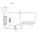
- the drive unit shown in FIG. 1 has an internal combustion engine 1 on. There is one in the liquid cooling circuit shown here Coolant pump 2, a cooler 3, a fan 4, an expansion tank 5 and a thermostat 6.
- the coolant pump 2 a suction line 2.1 and another suction line 2.2. You can also see the flight circuit 4.1 of the fan.
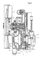
- FIG. 3 shows the following in detail: The crankshaft 1.1 of the engine 1, a retarder 7 with a rotor blade wheel 7.1 and a stator blade wheel 7.2, a sealing element water / oil 8, a pump wheel 2.3 of the coolant pump, the fan 4 with the fan shaft 4.1.
- the suction line 2.1 is accommodated in a cover body - see FIG. 2.
- a torsional vibration damper 9 can also be seen.
Description
Die Erfindung betrifft eine Antriebseinheit, insbesondere für ein
Kraftfahrzeug, mit einem Verbrennungsmotor und einem Getriebe, ferner
mit einem Flüssigkeits-Kühlkreislauf sowie mit einem
Drehschwingungsdämpfer. Antriebseinheiten dieser Art sind aus
zahlreichen Druckschriften bekannt geworden. Es wird beispielsweise
verwiesen auf
Bei diesen Antriebseinheiten fällt an verschiedenen Stellen während des Betriebes Wärme an, die abgeführt werden muß. Eine solche Wärmequelle stellt der Retarder dar, der bei Bremsung aus hoher Fahrgeschwindigkeit kinetische Bremsenergie aufnimmt und in Wärme umsetzt. Gemäß Dokument (1) kann die im Retarder an die Bremsflüssigkeit übergegangene Wärme mittels eines speziellen Wärmetauschers dem Kühlmittel oder der Umgebungsluft zugeführt werden.These drive units fall at various points during the Operating heat that must be dissipated. Such a source of heat represents the retarder when braking from high driving speed absorbs kinetic braking energy and converts it into heat. According to Document (1) can be the one transferred to the brake fluid in the retarder Heat using a special heat exchanger, the coolant or Ambient air are supplied.
Eine weitere Wärmequelle stellt der Antriebsmotor dar, dessen Wärmeabfuhr von entscheidender Bedeutung ist. Bei der Antriebseinheit gemäß Dokument (4) wird das Kühlmittel, das den Motor kühlt, zugleich als Betriebsflüssigkeit für den Retarder verwendet. Another source of heat is the drive motor, the Heat dissipation is vital. With the drive unit According to document (4), the coolant that cools the engine is also used as Operating fluid used for the retarder.
Die üblichen Vskositäts-Drehschwingungsdämpfer umfassen u.a. einen massebehafteten Ring, der einen möglichst großen Durchmesser hat und der sich innerhalb eines Gehäuses befindet, das mit einer hochviskosen Masse, z.B. Silikonöl, ausgefüllt ist. Solche Drehschwingungsdämpfer werden üblicherweise mit Luft gekühlt.The usual viscosity torsional vibration dampers include i.a. one earth ring, which has the largest possible diameter and which is inside a housing with a highly viscous Mass, e.g. Silicone oil, is filled. Such torsional vibration dampers are usually cooled with air.
Bei der Konstruktion von Antriebseinheiten ist man ganz allgemein um eine möglichst kompakte Bauweise bemüht. Die Tendenz geht dahin, Bauteile einzusparen und die ganze Einheit kleiner und kostengünstiger zu gestalten.In general, when designing drive units, one is tried to be as compact as possible. The trend is going to components save and the whole unit smaller and cheaper too shape.
Eine Ausführung einer Antriebseinheit ist aus der Druckschrift GB 650,891 vorbekannt, umfassend einen Verbrennungsmotor mit einem Drehschwingungsdämpfer, welcher zum Zwecke der Kühlung in den Schmierölflüssigkeitskreislauf des Verbrennungsmotors eingeschaltet ist Dabei wird der zur Lagerschmierung dienende Flüssigkeitskreislauf durch den Dämpfer hindurch geleitet Es ist dabei zur Aufrechterhaltung des Kreislaufes erforderlich entsprechende Mittel, beispielsweise Pumpeinrichtungen vorzusehen. Diese müssen bei der Konzeption der Antriebseinheit bzw. des Flüssigkeitskreislaufes mit berücksichtigt werden, insbesondere hinsichtlich des erforderlichen Bauraumes und der Ansteuerung. Hierbei wurden Fortschritte erzielt, die aber noch nicht ausreichen.An embodiment of a drive unit is from GB 650,891 previously known, comprising an internal combustion engine with a torsional vibration damper, which for the purpose of cooling in the lubricating oil liquid circuit of the internal combustion engine is switched on Bearing lubrication fluid circuit through the damper passed through It is to maintain the circulation necessary means, such as pumping equipment provided. These must be considered when designing the drive unit or the Liquid cycle are taken into account, especially with regard the required installation space and control. Here were Progress has been made but is not yet sufficient.
Der Erfindung liegt die Aufgabe zugrunde, eine Antriebseinheit mit einem Motor, einem Getriebe, einem Flüssigkeits-Kühlkreislauf und einem Drehschwingungsdämpfer sowie gegebenenfalls weiteren Elementen derart zu gestalten, daß ein geringerer Bauraum, insbesondere eine geringere axiale Baulänge sowie ein geringeres Gewicht erzielbar sind als bei bekannten Antriebseinheiten.The invention has for its object a drive unit with a Engine, a transmission, a liquid cooling circuit and one Torsional vibration damper and possibly other elements such to design that a smaller space, in particular a smaller axial length and a lower weight can be achieved than with known drive units.
Diese Aufgabe wird durch die Merkmale von Anspruch 1 gelöst. This object is solved by the features of
Der wesentliche Gedanke der Erfinder besteht somit darin, den Drehschwingungsdämpfer einer solchen Antriebseinheit im Flüssigkeits-Kühlkreislauf anzuordnen. Dies bedeutet, daß die Kühlflüssigkeit des ohnehin vorhandenen Flüssigkeits-Kühlkreislaufes dazu ausgenutzt wird, auch den Drehschwingungsdämpfer zu kühlen.The main idea of the inventors is therefore that Torsional vibration damper of such a drive unit in To arrange liquid cooling circuit. This means that the Cooling liquid of the already existing liquid cooling circuit is used to cool the torsional vibration damper.
Der Gedanke läßt sich auf unterschiedliche Weise verwirklichen. So kann der Drehschwingungsdämpfer beispielsweise im Kurbelgehäuse angeordnet werden. Wird er außerhalb des Kurbelgehäuses angeordnet, so kann das Leitungssystem derart gestaltet und angeordnet werden, daß die Kühlflüssigkeit in die unmittelbare Nähe des Gehäuses des Drehschwingungsdämpfers geführt wird, so daß es zu einem Wärmeaustausch kommen kann. The idea can be realized in different ways. So can the torsional vibration damper, for example in the crankcase to be ordered. If it is placed outside the crankcase, so the line system can be designed and arranged in such a way that the Coolant in the immediate vicinity of the housing Torsional vibration damper is guided so that it becomes a Heat exchange can come.
Gemäß einem weiterführenden Gedanken kann der Drehschwingungsdämpfer außer seiner angestammten Funktion noch mit weiteren Funktionen ausgestattet werden. So kann er beispielsweise auf einer seiner Stirnflächen als Pumpenrad für die Kühlflüssigkeit gestaltet werden bzw. ein Pumpenrad tragen. Alternativ oder zusätzlich kann eine seiner Stirnflächen als Rotorschaufelrad eines Retarders ausgebildet werden.According to a further thought, the torsional vibration damper in addition to its traditional function with other functions be equipped. For example, it can be on one of its end faces be designed as a pump wheel for the coolant or a pump wheel wear. Alternatively or additionally, one of its end faces can be used as Rotor paddle wheel of a retarder are formed.
Die Erfindung ist anhand der Zeichnung näher erläutert. Darin ist im einzelnen
folgendes dargestellt:
Die in Figur 1 dargestellte Antriebseinheit weist einen Verbrennungsmotor 1
auf. In dem hier dargestellten Flüssigkeits-Kühlkreislauf befinden sich eine
Kühlflüssigkeitspumpe 2, ein Kühler 3, ein Lüfter 4, ein Ausgleichsbehälter 5
sowie ein Thermostat 6.The drive unit shown in FIG. 1 has an
In Figur 2 sind die folgenden Bauteile erkennbar:
Die Kühlflüssigkeitspumpe 2, eine Saugleitung 2.1 und eine weitere
Saugleitung 2.2. Ferner erkennt man den Flugkreis 4.1 des Lüfters.The following components can be seen in FIG. 2:
The
Figur 3 läßt im einzelnen folgendes erkennen:
Die Kurbelwelle 1.1 des Motors 1, einen Retarder 7 mit Rotorschaufelrad 7.1
und Statorschaufelrad 7.2, ein Dichtelement Wasser/Öl 8, ein Pumpenrad 2.3
der Kühlflüssigkeitspumpe, den Lüfter 4 mit der Lüfterwelle 4.1. In einem
Deckelkörper ist die Saugleitung 2.1 untergebracht - siehe Figur 2. Man
erkennt weiterhin einen Drehschwingungsdämpfer 9.Figure 3 shows the following in detail:
The crankshaft 1.1 of the
Claims (4)
- A drive unit, especially for a motor vehicle, with an internal combustion engine (1) and a gear, a liquid cooling circuit, a torsional vibration damper (9), with said torsional vibration damper (9) being connected in the liquid cooling circuit, characterized by the following feature:
the torsional vibration damper (9) is arranged on one of its face sides as a rotor blade wheel (7.1) of a retarder. - A drive unit as claimed in claim 1, characterized in that the torsional vibration damper (9) is arranged within the crankcase.
- A drive unit as claimed in claim 1, characterized in that the torsional vibration damper (9) is arranged within an intermediate housing which on its part is attached to a face side of the crankcase.
- A drive unit as claimed in one of the claims 1 to 3, characterized in that the torsional vibration damper (9) is arranged on the other face side as an impeller (2.3) for the coolant.
Applications Claiming Priority (2)
| Application Number | Priority Date | Filing Date | Title |
|---|---|---|---|
| DE19641451 | 1996-10-08 | ||
| DE19641451A DE19641451A1 (en) | 1996-10-08 | 1996-10-08 | Liquid-cooled automotive power unit with gearbox |
Publications (3)
| Publication Number | Publication Date |
|---|---|
| EP0835992A2 EP0835992A2 (en) | 1998-04-15 |
| EP0835992A3 EP0835992A3 (en) | 1999-09-15 |
| EP0835992B1 true EP0835992B1 (en) | 2002-12-11 |
Family
ID=7808163
Family Applications (1)
| Application Number | Title | Priority Date | Filing Date |
|---|---|---|---|
| EP97116123A Expired - Lifetime EP0835992B1 (en) | 1996-10-08 | 1997-09-17 | Propulsion unit, especially for a motor vehicle |
Country Status (4)
| Country | Link |
|---|---|
| EP (1) | EP0835992B1 (en) |
| JP (1) | JP3782877B2 (en) |
| DE (2) | DE19641451A1 (en) |
| TR (1) | TR199701131A3 (en) |
Families Citing this family (3)
| Publication number | Priority date | Publication date | Assignee | Title |
|---|---|---|---|---|
| GB9819261D0 (en) * | 1998-09-03 | 1998-10-28 | Concentric Pumps Ltd | Improvements to rotary pumps |
| DE10303416B4 (en) * | 2003-01-29 | 2006-02-16 | Voith Turbo Gmbh & Co. Kg | Wärmetauscherbaueinheit |
| DE102018210451A1 (en) | 2018-06-27 | 2020-01-02 | Bayerische Motoren Werke Aktiengesellschaft | Reciprocating internal combustion engine |
Family Cites Families (11)
| Publication number | Priority date | Publication date | Assignee | Title |
|---|---|---|---|---|
| DE512454C (en) * | 1928-02-06 | 1930-11-12 | E H Hugo Junkers Dr Ing | Torsional vibration damper with fluid circulation |
| NL51942C (en) * | 1938-01-29 | |||
| GB650891A (en) * | 1948-01-29 | 1951-03-07 | Brush Electrical Eng | Improvements relating to torsional vibration dampers |
| NL6913276A (en) | 1968-09-17 | 1970-03-19 | ||
| US3720372A (en) | 1971-12-09 | 1973-03-13 | Gen Motors Corp | Means for rapidly heating interior of a motor vehicle |
| DE2734769A1 (en) * | 1977-08-02 | 1979-02-15 | Maschf Augsburg Nuernberg Ag | RESONANCE ROTARY VIBRATION DAMPER |
| US4257370A (en) * | 1978-12-29 | 1981-03-24 | Cummins Engine Company, Inc. | Combined gear cover and mount for an internal combustion engine |
| DE3301560C1 (en) | 1983-01-19 | 1984-04-05 | Daimler-Benz Ag, 7000 Stuttgart | Control of the heating power of a hydrodynamic brake |
| JPS6159041A (en) * | 1984-08-30 | 1986-03-26 | Sanshin Ind Co Ltd | Vibration damping device of marine propeller |
| DE3713580C1 (en) | 1987-04-23 | 1988-11-10 | Voith Turbo Kg | Drive system with a hydrodynamic retarder |
| DE4440163C2 (en) * | 1994-11-10 | 1997-02-20 | Voith Turbo Kg | Drive unit with an internal combustion engine and a hydrodynamic retarder |
-
1996
- 1996-10-08 DE DE19641451A patent/DE19641451A1/en not_active Withdrawn
-
1997
- 1997-09-17 DE DE59708936T patent/DE59708936D1/en not_active Expired - Fee Related
- 1997-09-17 EP EP97116123A patent/EP0835992B1/en not_active Expired - Lifetime
- 1997-10-06 JP JP27316897A patent/JP3782877B2/en not_active Expired - Fee Related
- 1997-10-08 TR TR97/01131A patent/TR199701131A3/en unknown
Also Published As
| Publication number | Publication date |
|---|---|
| JP3782877B2 (en) | 2006-06-07 |
| TR199701131A2 (en) | 1998-04-21 |
| EP0835992A3 (en) | 1999-09-15 |
| EP0835992A2 (en) | 1998-04-15 |
| JPH10115228A (en) | 1998-05-06 |
| TR199701131A3 (en) | 1998-04-21 |
| DE19641451A1 (en) | 1997-03-20 |
| DE59708936D1 (en) | 2003-01-23 |
Similar Documents
| Publication | Publication Date | Title |
|---|---|---|
| EP2706217B1 (en) | Vehicle drive train with a retarder and an expansion machine | |
| EP2480438B1 (en) | Drive train with a hydrodynamic retarder | |
| DE19509417A1 (en) | Drive unit | |
| EP0722867B1 (en) | Drive unit with an internal combustion engine and a hydrodynamic retarder. | |
| DE4440164C2 (en) | Drive unit with an internal combustion engine and a hydrodynamic retarder | |
| EP0835992B1 (en) | Propulsion unit, especially for a motor vehicle | |
| DE4440163C2 (en) | Drive unit with an internal combustion engine and a hydrodynamic retarder | |
| EP1081003B1 (en) | Assembly for an internal combustion engine | |
| DE4440165C2 (en) | Drive unit with an internal combustion engine and a hydrodynamic retarder | |
| DE102014221667A1 (en) | Hybrid drive arrangement of a motor vehicle | |
| DE102011012641B4 (en) | Drive device with rocker arm and use of a motor swingarm | |
| EP0716966A2 (en) | Propulsion unit | |
| DE10203259A1 (en) | Drive for a motor vehicle | |
| DE19641450B4 (en) | Drive unit, in particular for a motor vehicle | |
| DE4445178C2 (en) | Drive system for commercial vehicles with a primary retarder | |
| EP0711693A1 (en) | Drive unit with an internal combustion engine and a hydrodynamic retarder | |
| DE102019133322A1 (en) | Drive with internal rotor shaft cooling of an electric motor and a motor vehicle with such a drive | |
| DE19544189C2 (en) | Drive unit | |
| DE102018214275A1 (en) | Electric ship propulsion module and driveline assembly for a ship | |
| DE102013003754A1 (en) | Cooling system, in particular for a motor vehicle | |
| EP0880217A2 (en) | Assembly of a combustion engine, an electrical generator and a pump unit | |
| DE102021209648A1 (en) | Drive train for a motor vehicle | |
| DE202020106699U1 (en) | Cooling system | |
| DE102020107700A1 (en) | Hybrid drive device with a fluid delivery device | |
| DE102004018225A1 (en) | Cooling system for sports car gearbox has oil pump powered by power take-off point from gearbox |
Legal Events
| Date | Code | Title | Description |
|---|---|---|---|
| PUAI | Public reference made under article 153(3) epc to a published international application that has entered the european phase |
Free format text: ORIGINAL CODE: 0009012 |
|
| AK | Designated contracting states |
Kind code of ref document: A2 Designated state(s): DE FR GB IT NL SE |
|
| AX | Request for extension of the european patent |
Free format text: AL;LT;LV;RO;SI |
|
| PUAL | Search report despatched |
Free format text: ORIGINAL CODE: 0009013 |
|
| AK | Designated contracting states |
Kind code of ref document: A3 Designated state(s): AT BE CH DE DK ES FI FR GB GR IE IT LI LU MC NL PT SE |
|
| AX | Request for extension of the european patent |
Free format text: AL;LT;LV;RO;SI |
|
| 17P | Request for examination filed |
Effective date: 19991001 |
|
| AKX | Designation fees paid |
Free format text: DE FR GB IT NL SE |
|
| 17Q | First examination report despatched |
Effective date: 20010309 |
|
| GRAG | Despatch of communication of intention to grant |
Free format text: ORIGINAL CODE: EPIDOS AGRA |
|
| GRAG | Despatch of communication of intention to grant |
Free format text: ORIGINAL CODE: EPIDOS AGRA |
|
| GRAH | Despatch of communication of intention to grant a patent |
Free format text: ORIGINAL CODE: EPIDOS IGRA |
|
| RAP1 | Party data changed (applicant data changed or rights of an application transferred) |
Owner name: MAN NUTZFAHRZEUGE AKTIENGESELLSCHAFT Owner name: VOITH TURBO GMBH & CO. KG |
|
| GRAH | Despatch of communication of intention to grant a patent |
Free format text: ORIGINAL CODE: EPIDOS IGRA |
|
| GRAA | (expected) grant |
Free format text: ORIGINAL CODE: 0009210 |
|
| AK | Designated contracting states |
Kind code of ref document: B1 Designated state(s): DE FR GB IT NL SE |
|
| REG | Reference to a national code |
Ref country code: GB Ref legal event code: FG4D Free format text: NOT ENGLISH |
|
| REF | Corresponds to: |
Ref document number: 59708936 Country of ref document: DE Date of ref document: 20030123 |
|
| REG | Reference to a national code |
Ref country code: SE Ref legal event code: TRGR |
|
| GBT | Gb: translation of ep patent filed (gb section 77(6)(a)/1977) |
Effective date: 20030415 |
|
| ET | Fr: translation filed | ||
| PGFP | Annual fee paid to national office [announced via postgrant information from national office to epo] |
Ref country code: FR Payment date: 20030917 Year of fee payment: 7 |
|
| PGFP | Annual fee paid to national office [announced via postgrant information from national office to epo] |
Ref country code: SE Payment date: 20030922 Year of fee payment: 7 |
|
| PGFP | Annual fee paid to national office [announced via postgrant information from national office to epo] |
Ref country code: NL Payment date: 20030923 Year of fee payment: 7 |
|
| PLBE | No opposition filed within time limit |
Free format text: ORIGINAL CODE: 0009261 |
|
| STAA | Information on the status of an ep patent application or granted ep patent |
Free format text: STATUS: NO OPPOSITION FILED WITHIN TIME LIMIT |
|
| 26N | No opposition filed |
Effective date: 20030912 |
|
| PG25 | Lapsed in a contracting state [announced via postgrant information from national office to epo] |
Ref country code: SE Free format text: LAPSE BECAUSE OF NON-PAYMENT OF DUE FEES Effective date: 20040918 |
|
| PG25 | Lapsed in a contracting state [announced via postgrant information from national office to epo] |
Ref country code: NL Free format text: LAPSE BECAUSE OF NON-PAYMENT OF DUE FEES Effective date: 20050401 |
|
| EUG | Se: european patent has lapsed | ||
| PG25 | Lapsed in a contracting state [announced via postgrant information from national office to epo] |
Ref country code: FR Free format text: LAPSE BECAUSE OF NON-PAYMENT OF DUE FEES Effective date: 20050531 |
|
| NLV4 | Nl: lapsed or anulled due to non-payment of the annual fee |
Effective date: 20050401 |
|
| REG | Reference to a national code |
Ref country code: FR Ref legal event code: ST |
|
| PG25 | Lapsed in a contracting state [announced via postgrant information from national office to epo] |
Ref country code: IT Free format text: LAPSE BECAUSE OF NON-PAYMENT OF DUE FEES Effective date: 20050917 |
|
| PGFP | Annual fee paid to national office [announced via postgrant information from national office to epo] |
Ref country code: GB Payment date: 20070824 Year of fee payment: 11 |
|
| PGFP | Annual fee paid to national office [announced via postgrant information from national office to epo] |
Ref country code: DE Payment date: 20080930 Year of fee payment: 12 |
|
| GBPC | Gb: european patent ceased through non-payment of renewal fee |
Effective date: 20080917 |
|
| PG25 | Lapsed in a contracting state [announced via postgrant information from national office to epo] |
Ref country code: GB Free format text: LAPSE BECAUSE OF NON-PAYMENT OF DUE FEES Effective date: 20080917 |
|
| PG25 | Lapsed in a contracting state [announced via postgrant information from national office to epo] |
Ref country code: DE Free format text: LAPSE BECAUSE OF NON-PAYMENT OF DUE FEES Effective date: 20100401 |