EP0835761A2 - Ink-jet printing apparatus and ink-jet printing method - Google Patents
Ink-jet printing apparatus and ink-jet printing method Download PDFInfo
- Publication number
- EP0835761A2 EP0835761A2 EP97307953A EP97307953A EP0835761A2 EP 0835761 A2 EP0835761 A2 EP 0835761A2 EP 97307953 A EP97307953 A EP 97307953A EP 97307953 A EP97307953 A EP 97307953A EP 0835761 A2 EP0835761 A2 EP 0835761A2
- Authority
- EP
- European Patent Office
- Prior art keywords
- printing
- head
- region
- ink
- array width
- Prior art date
- Legal status (The legal status is an assumption and is not a legal conclusion. Google has not performed a legal analysis and makes no representation as to the accuracy of the status listed.)
- Granted
Links
Images


Classifications
-
- B—PERFORMING OPERATIONS; TRANSPORTING
- B41—PRINTING; LINING MACHINES; TYPEWRITERS; STAMPS
- B41J—TYPEWRITERS; SELECTIVE PRINTING MECHANISMS, i.e. MECHANISMS PRINTING OTHERWISE THAN FROM A FORME; CORRECTION OF TYPOGRAPHICAL ERRORS
- B41J3/00—Typewriters or selective printing or marking mechanisms characterised by the purpose for which they are constructed
- B41J3/54—Typewriters or selective printing or marking mechanisms characterised by the purpose for which they are constructed with two or more sets of type or printing elements
- B41J3/543—Typewriters or selective printing or marking mechanisms characterised by the purpose for which they are constructed with two or more sets of type or printing elements with multiple inkjet print heads
-
- B—PERFORMING OPERATIONS; TRANSPORTING
- B41—PRINTING; LINING MACHINES; TYPEWRITERS; STAMPS
- B41J—TYPEWRITERS; SELECTIVE PRINTING MECHANISMS, i.e. MECHANISMS PRINTING OTHERWISE THAN FROM A FORME; CORRECTION OF TYPOGRAPHICAL ERRORS
- B41J11/00—Devices or arrangements of selective printing mechanisms, e.g. ink-jet printers or thermal printers, for supporting or handling copy material in sheet or web form
- B41J11/0015—Devices or arrangements of selective printing mechanisms, e.g. ink-jet printers or thermal printers, for supporting or handling copy material in sheet or web form for treating before, during or after printing or for uniform coating or laminating the copy material before or after printing
- B41J11/002—Curing or drying the ink on the copy materials, e.g. by heating or irradiating
- B41J11/0021—Curing or drying the ink on the copy materials, e.g. by heating or irradiating using irradiation
-
- B—PERFORMING OPERATIONS; TRANSPORTING
- B41—PRINTING; LINING MACHINES; TYPEWRITERS; STAMPS
- B41J—TYPEWRITERS; SELECTIVE PRINTING MECHANISMS, i.e. MECHANISMS PRINTING OTHERWISE THAN FROM A FORME; CORRECTION OF TYPOGRAPHICAL ERRORS
- B41J11/00—Devices or arrangements of selective printing mechanisms, e.g. ink-jet printers or thermal printers, for supporting or handling copy material in sheet or web form
- B41J11/0015—Devices or arrangements of selective printing mechanisms, e.g. ink-jet printers or thermal printers, for supporting or handling copy material in sheet or web form for treating before, during or after printing or for uniform coating or laminating the copy material before or after printing
- B41J11/002—Curing or drying the ink on the copy materials, e.g. by heating or irradiating
- B41J11/0022—Curing or drying the ink on the copy materials, e.g. by heating or irradiating using convection means, e.g. by using a fan for blowing or sucking air
-
- B—PERFORMING OPERATIONS; TRANSPORTING
- B41—PRINTING; LINING MACHINES; TYPEWRITERS; STAMPS
- B41J—TYPEWRITERS; SELECTIVE PRINTING MECHANISMS, i.e. MECHANISMS PRINTING OTHERWISE THAN FROM A FORME; CORRECTION OF TYPOGRAPHICAL ERRORS
- B41J3/00—Typewriters or selective printing or marking mechanisms characterised by the purpose for which they are constructed
- B41J3/407—Typewriters or selective printing or marking mechanisms characterised by the purpose for which they are constructed for marking on special material
- B41J3/4078—Printing on textile
-
- B—PERFORMING OPERATIONS; TRANSPORTING
- B41—PRINTING; LINING MACHINES; TYPEWRITERS; STAMPS
- B41J—TYPEWRITERS; SELECTIVE PRINTING MECHANISMS, i.e. MECHANISMS PRINTING OTHERWISE THAN FROM A FORME; CORRECTION OF TYPOGRAPHICAL ERRORS
- B41J3/00—Typewriters or selective printing or marking mechanisms characterised by the purpose for which they are constructed
- B41J3/42—Two or more complete typewriters coupled for simultaneous operation
-
- B—PERFORMING OPERATIONS; TRANSPORTING
- B41—PRINTING; LINING MACHINES; TYPEWRITERS; STAMPS
- B41J—TYPEWRITERS; SELECTIVE PRINTING MECHANISMS, i.e. MECHANISMS PRINTING OTHERWISE THAN FROM A FORME; CORRECTION OF TYPOGRAPHICAL ERRORS
- B41J3/00—Typewriters or selective printing or marking mechanisms characterised by the purpose for which they are constructed
- B41J3/60—Typewriters or selective printing or marking mechanisms characterised by the purpose for which they are constructed for printing on both faces of the printing material
Definitions
- the present invention relates to an ink-jet printing apparatus and an ink-jet printing method, particularly suitable for textile printing, which employs textile or cloth as a printing medium, and ejects an ink to the textile by means of an ink-jet head as a printing head.
- Japanese Patent Application Laid-Open No. 212851/1993 discloses one embodiment of a textile printing apparatus employing an ink-jet system.
- this type of textile printing apparatus performs printing by ejecting an ink from an ink-jet head to a textile as a printing medium, transported in a vertical direction.
- a printing portion performing ink ejection a printing unit having the ink-jet head and a transporting mechanism including a metallic endless belt, i.e., a transporting belt, are arranged in opposition across the textile.
- the textile is adhered on the surface of the transporting belt to certainly maintain flatness. Then, by intermittently driving the transporting belt, the textile is transported for a predetermined width.
- the textile is printed per one printing width by the known serial printing system, and thereafter is applied an appropriate tension by a textile take-up roller arranged at the most downstream side of the transporting path. Then, at an end portion of the transporting belt, the textile is peeled off the transporting belt and taken up on the take-up roller via a textile path.
- drying process is performed for the ink in the printing portion of the textile by means of a drying process apparatus.
- a drying process apparatus a system blowing a hot air on the printing surface of the textile or a system irradiating an infrared ray on the printing surface of the textile may be selected arbitrary. Such drying processes are particularly effective when a liquid state printing agent is employed.
- a textile printing ink applied for the textile by the ink-jet type textile printing merely adheres on the textile, it is required to fix the coloring agent in the ink, such as dye by making impregnation. It is typical for rough standard of impregnation amount to evaluate by strike through amount (permeation amount of the ink towards the back side of textile printing surface) by observation from the back side as non-printed surface.
- strike through amount permeation amount of the ink towards the back side of textile printing surface
- an ink-jet printing apparatus forming an image on a printing medium with employing a printing head, comprising:
- an ink-jet printing method comprising:
- This embodiment is a textile printing apparatus employing an ink-jet system.
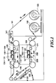
- Fig. 1 shows a brief construction of a full-color ink-jet textile printing apparatus.
- a reference numeral 101 denotes a printing medium consisted of a textile, such as cotton, silk, nylon, polyester, and the like.
- a reference numeral 102 denotes a feed roller equipping the printing medium 101 is wound in roll form.
- a reference numeral 103 denotes a take-up roller taking up a printing medium 101 being printed.
- a reference numeral 104 denotes a first printing control unit (a first printing means). This first printing control unit 104 performs printing control of a first printing head 208 and a second printing head 209.
- the first printing head 208 is constructed by ink-jet heads 105 to 112, which are positioned at upstream side of the transporting path of the printing medium 101.
- a reference numeral 105 denotes a first pale magenta multi-nozzle head (a first pale magenta head) for ejecting a pale magenta ink.
- a reference numeral 106 denotes a first yellow multi-nozzle head (a first yellow head) for ejecting a yellow ink.
- a reference numeral 107 denotes a first orange multi-nozzle head (a first orange head) for ejecting an orange ink.
- a reference numeral 108 denotes a first magenta multi-nozzle head (a first magenta head) for ejecting a magenta ink.
- a reference numeral 109 denotes a first pale cyan multi-nozzle head (a first pale cyan head) for ejecting a pale cyan ink.
- a reference numeral 110 denotes a first cyan multi-nozzle head (a first cyan head) for ejecting a cyan ink.
- a reference numeral 111 denotes a first blue multi-nozzle head (a first blue head) for ejecting a blue ink.
- a reference numeral 112 denotes a first black multi-nozzle head (a first black head) for ejecting a black ink.
- Each of ink-jet heads 105 to 112 has a plurality of ejection openings and the length of the head parallels the transporting direction Y of the printing medium 101. These ink-jet heads 105 to 112 are sequentially arranged along the main-scanning direction Xa.
- a second printing head 209 is constructed by ink-jet heads 113 to 120, which are positioned at downstream side of a transporting path of the printing medium 101 and are arranged shifting for half of printing width (band width) in the transporting direction with respect to ink-jet heads 105 to 112.
- a reference numeral 113 denotes a second pale magenta multi-nozzle head (a second pale magenta head) for ejecting a pale magenta ink.
- a reference numeral 114 denotes a second yellow multi-nozzle head (a second yellow head) for ejecting a yellow ink.
- a reference numeral 115 denotes a second orange multi-nozzle head (a second orange head) for ejecting an orange ink.
- a reference numeral 116 denotes a second magenta multi-nozzle head (a second magenta head) for ejecting a magenta ink.
- a reference numeral 117 denotes a second pale cyan multi-nozzle head (a second pale cyan head) for ejecting a pale cyan ink.
- a reference numeral 118 denotes a second cyan multi-nozzle head (a second cyan head) for ejecting a cyan ink.
- a reference numeral 119 denotes a second blue multi-nozzle head (a second blue head) for ejecting a blue ink.
- a reference numeral 120 denotes a second black multi-nozzle head (a second black head) for ejecting a black ink.
- Each of ink-jet heads 113 to 120 has a plurality of ejection openings and the length of the head parallels the transporting direction Y of the printing medium 101. These ink-jet heads 113 to 120 are sequentially arranged along the main-scanning direction Xa.
- a reference numeral 121 denotes a first platen (first transporting means) transporting the printing medium. This first platen 121 is stretched by a plurality of rollers and moved in the direction shown by arrow A to transport the printing medium 101 in the direction shown by arrow B by friction with the printing medium 101.
- a reference numeral 122 denotes a dryer for drying the ink on the printing surface of the printing medium 101 immediately after printing. The dried printing medium 101 is turned over by the transporting means (both surface return means) to reverse transporting direction. Therefore, the back side surface of the printing medium 101 is located at the upper position and the front side surface of the dried printing medium 101 is located at the lower position.
- a reference numeral 123 denotes a second printing control unit (a second printing means). This second printing control unit 123 performs printing control of a third printing head 210 and a forth printing head 211.
- the third printing head 210 is constructed by ink-jet heads 124 to 131, which are positioned at upstream side of the transporting path of the printing medium 101.
- a reference numeral 124 denotes a third pale magenta multi-nozzle head (a third pale magenta head) for ejecting a pale magenta ink.
- a reference numeral 125 denotes a third yellow multi-nozzle head (a third yellow head) for ejecting a yellow ink.
- a reference numeral 126 denotes a third orange multi-nozzle head (a third orange head) for ejecting an orange ink.
- a reference numeral 127 denotes a third magenta multi-nozzle head (a third magenta head) for ejecting a magenta ink.
- a reference numeral 128 denotes a third pale cyan multi-nozzle head (a third pale cyan head) for ejecting a pale cyan ink.
- a reference numeral 129 denotes a third cyan multi-nozzle head (a third cyan head) for ejecting a cyan ink.
- a reference numeral 130 denotes a third blue multi-nozzle head (a third blue head) for ejecting a blue ink.
- a reference numeral 131 denotes a third black multi-nozzle head (a third black head) for ejecting a black ink.
- Each of ink-jet heads 124 to 131 has a plurality of ejection openings and the length of the head parallels the transporting direction Y of the printing medium 101. These ink-jet heads 124 to 131 are sequentially arranged along the main-scanning direction Xa.
- a forth printing head 211 is constructed by ink-jet heads 132 to 139, which are positioned at downstream side of a transporting path of the printing medium 101 and are arranged shifting for half of printing width (bandwidth) in the transporting direction with respect to ink-jet heads 124 to 131.
- a reference numeral 132 denotes a forth pale magenta multi-nozzle head (a forth pale magenta head) for ejecting a pale magenta ink.
- a reference numeral 133 denotes a forth yellow multi-nozzle head (a forth yellow head) for ejecting a yellow ink.
- a reference numeral 134 denotes a forth orange multi-nozzle head (a forth orange head) for ejecting an orange ink.
- a reference numeral 135 denotes a forth magenta multi-nozzle head (a forth magenta head) for ejecting a magenta ink.
- a reference numeral 136 denotes a forth pale cyan multi-nozzle head (a forth pale cyan head) for ejecting a pale cyan ink.
- a reference numeral 137 denotes a forth cyan multi-nozzle head (a forth cyan head) for ejecting a cyan ink.
- a reference numeral 138 denotes a forth blue multi-nozzle head (a forth blue head) for ejecting a blue ink.
- a reference numeral 139 denotes a forth black multi-nozzle head (a forth black head) for ejecting a black ink.
- Each of ink-jet heads 132 to 139 has a plurality of ejection openings and the length of the head parallels the transporting direction Y of the printing medium 101. These ink-jet heads 132 to 139 are sequentially arranged along the main-scanning direction Xa.
- a reference numeral 140 denotes a second platen (second transporting means) for transporting the printing medium. This second platen 140 is stretched by a plurality of rollers and moved in a direction shown by an arrow C to transport the printing medium 101 in a direction shown by arrow B by friction with the printing medium 101.
- a reference numeral 141 denotes a dryer for drying the ink on the printing surface of the printing medium immediately after printing.
- Fig. 2 shows a construction of a circuit portion performing printing process in the ink-jet textile printing system.
- the first printing head 208, the second printing head 209, the third printing head 210 and the fourth printing head 211 perform bi-directional printing.
- the reference numeral 201 denotes a host computer controlling the ink-jet type textile printing system.
- a printing image data transferred from the host computer 201 via a general purpose interface bus (GPIB) interface is once stored in a frame memory 202 and is sequentially read out to a sequential multi-scanning portion 203 by generating a printing start command.
- the sequential multi-scanning portion 203 distributingly transfer the printing image data received from the frame memory 202 to a first band memory 204 and a second band memory 205.
- the printing image data received from the frame memory 292 is distributingly transferred to the third band memory 206 and the fourth band memory 207.
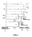
- Fig. 3 is an illustration for explaining a printing process by the first printing controller portion 104 in the ink-jet textile printing apparatus in Figs. 1 and 2.
- the first printing head 208 connected to the first band memory 204 is positioned at upstream side of the transporting direction Y of the printing medium 101 and thus performs first printing for the printing medium 101.
- the first printing head 208 includes all of the ink-jet heads 105 to 112
- the second printing head 209 includes all of the ink-jet heads 113 to 120.
- printing operation is performed depending upon the printing data of the first band memory 204 distributed by the sequential multi-scanning portion 203 (Japanese Patent Application Laid-Open No. 70990/1997). Then, the portion 301a of the printing medium which is printed during scanning in the forward direction Xa employing all of the ejection openings of the first printing head 208 is transported by a predetermined amount corresponding to an arrangement width L of the ejection openings of the printing head to be placed in a region corresponding to a printing region of the second printing head 209. On the basis of the remaining second printing data distributed to the region 301b according to the multi-scanning system, printing is performed by the second printing head 209.
- the first printing head 208 and the second printing head 209 are mutually shifted the printing position in the magnitude corresponding to one half of the arrangement width L of the ejection openings. Therefore, the second printing head 209 performs printing during scanning in the reverse direction Xb for a region 302a corresponding to the upper half of the region 301b where printing has already been performed by the first printing head 208.
- the printing medium 101 is transported for an amount corresponding to the arrangement width L of the ejection openings, and then the region 301b of the printing medium 101 reaches a region 301c. Then, by using the ejection openings in the upper half of the second printing head 209, the lower half of the region 301b of the region 301c printed by the first printing head 208.
- the regions printed by the first printing head 208 and the second printing head 209 can be represented by the reference numeral 302.
- the printing data upon printing means the data for printing by thinning dots to be printed in staggered fashion and data not performing printing (data not performing ejection) is provided for the thinned portion.
- the multi-scanning system is employed, so that respective lines of the regions 302 are formed by inks ejected from respectively different ejection openings of the first printing head 208 and the second printing head 209.
- fluctuation of density, stripe or so forth due to diameter of ejection openings, direction of ejection of the ink-jet head and so forth can be distributed.
- control is performed for the third printing head 210 and the fourth printing head 211.
- Fig. 4 is an illustration for explaining double sided printing process for realizing good strike through by printing mirror images on the both surfaces by the ink-jet textile printing apparatus in Figs. 1 and 2.
- Registration control with respect to the transporting direction Y is performed by using a registration control portion 405 for performing registration control for double sided printing as shown in Fig. 4.
- registration control with respect to the carriage scanning directions Xa and Xb can be performed by a printing position detection control portion 212 as shown in Fig. 2.
- the registration control portion 405 for the double sided printing as shown in Fig. 4 includes a CPU 405a, a ROM 405b, and the like.
- the CPU 405a performs arithmetic processing associated with the registration control.
- the ROM 405b stores a control program for registration control.
- Fig. 5 is a flowchart for explaining the control program performing registration control.
- a front surface printing position reference mark 401 is printed in a region other than an image printing region on the front surface side (step S1).
- printing of the image data is initiated from a position transported for a distance greater than or equal to a distance 402 between the third printing head 210 and a front side surface reference area sensor 404, using the first printing head 208.
- the printing medium 101, on which the front surface side printing position reference mark 401 is printed, is transported to a region of the second print control portion 123 as shown in Fig. 4 (step S2).
- Fig. 4 shows a manner of printing on the back side surface of the printing medium.
- the registration control portion 405 for double sided printing feeds a control signal Sa for the third printing head 210.
- the third printing head repeats printing of a back side surface printing position reference mark 403 in a region other than an image printing region on the back side surface (step S3).
- step S4 sequential printing of the back side surface printing position reference mark 403 by the third printing head 210 is terminated (step S4).
- a signal P indicative of a length of sequential printing of the back side surface printing position reference mark 403 from a timing where the front side surface printing position reference mark 401 to the terminating position of sequential printing of the back side surface printing position reference mark 403 is detected.
- the detected signal P is fed to the registration control portion 405 for the double sided printing.
- a sequential printing length of the back side surface printing position reference mark 403 is calculated on the basis of the detected signal P (step S5). Then, by comparing the sequential printing length of the back side surface printing position reference mark 403 thus calculated with the distance 402 in the transporting direction (distance between the third printing head 210 and the front side surface area sensor 404), a position offset amount of the third printing head 210 is derived (step S6).
- the position offset amount corresponds to the offset amount of the printing positions at the front side surface and the reverse side surface in the transporting direction Y.
- the control signals Sa and Sb and a motor control signal Sc are generated.
- Rotation control of the second platen 140 is performed based on the motor control signal Sc.
- ink ejection timings of the third printing head 210 and the fourth printing head 211 are controlled on the basis of the control signals Sa and Sb (step S7).
- position offset of the printing positions on the front side surface and the back side surface in the transporting direction Y can be corrected. It should be noted that, as a cause of the offset in the transporting direction, position error possibly caused in assembling the printing head and the like can be considered.
- the printing position detection control portion 212 as shown in Fig. 2 incorporates a CPU 212a, a ROM 212b, and the like.
- the ROM 212b stores a control program for registration control.
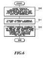
- Fig. 6 is a flowchart for explaining control program performing registration control.
- the position of the front side surface printing position reference mark 401 is detected by the front side surface reference area sensor 404, and the position of the back side surface printing position reference mark 403 is detected by the back side surface reference area sensor 406 (step S10).
- the position signals thus detected are fed to the printing position detection control portion 212.
- arithmetic process for generating timing control signals Ta and Tb for adjusting timing of data output of the third band memory 206 and the fourth band memory 207 on the basis of the position signals of the detected marks 401 and 403 (step S11).
- the timing control signals Ta and Tb generated by the printing position detection control portion 212 are fed to the third band memory 206 and the fourth band memory 207 (step S12). According to feeding timing, timings for outputting data from the third band memory 206 and the fourth band memory 207 to the third printing head 210 and the fourth printing head are adjusted. By this, ejection timings of inks from the third printing head 210 and the fourth printing head 211 can be controlled. Therefore, position offset of the printing positions on the front side surface and the back side surface in the carriage scanning directions Xa and Xb can be corrected.
- the third printing head 210 and the fourth printing head 211 initiate printing of the image data.
- the carriage scanning directions Xa and Xb by performing printing in the opposite direction to that of the first print control portion, clear image with strike through can be produced.
- Decision whether the second print control portion 123 is operated for printing in the opposite direction to that of the first print control portion 104, is made depending upon sequential order to store the image data in the third band memory 206 and the fourth band memory 207.
- printing is performed on the front side surface of the printing medium and then printing is performed on the back side surface of the printing medium with registering the image on the back side surface with respect to the image on the front side surface.
- the present invention is not limited to this specific embodiment.
- printing is performed on the back side surface of the printing medium and then printing is performed on the front side surface of the printing medium with registering the image on the front side surface with respect to the image on the back side surface.
- the textile as the printing medium is such a type that the front and back side surfaces are not specified, printing is performed on one side surface of the printing medium and then printing is performed on the other side surface of the printing medium with registering the image on the other side surface with respect to the image on one side surface.
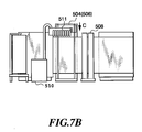
- Figs. 7A and 7B show general construction of a full color ink-jet textile printing apparatus.
- the reference numeral 501 denotes a printing medium consisted of a textile, such as cotton, silk, nylon, polyester, and the like.
- the reference numeral 502 denotes a feed roller, on which the printing medium 501 is wound in roll form.
- the reference numeral 504 denotes a first print control portion which has similar construction to that of the first print control portion 104 shown in Fig. 1.
- the reference numeral 505 denotes a first platen transporting the printing medium 501.
- the first platen 505 is stretched by a plurality of rollers and moves in the direction of arrow A to transport the printing medium 501 in the direction of arrow B by friction with the printing medium 501.
- the reference numeral 506 denotes a second print control portion which has similar construction to that of the second print control portion 123 of Fig. 1.
- the printing medium 501 is dried by a dryer 508.
- a second platen 509 for transporting the printing medium with preventing twisting which second platen 509 is stretched by a plurality of rollers.
- the printing medium 501 is taken up by a take-up roller 503 by friction with the printing medium 501.
- the reference numeral 510 is a main ink tank and a pump device supplying a textile printing ink.
- the main ink tank and the pump device 510 supplies the textile printing ink to a sub-tank 511 which moves together with the first printing head 504 and the second printing head 506 scanning in the direction of arrow C.
- registration for the double sided printing can be done by a complicated control method similar to the double sided printing process described with respect to the first embodiment with reference to Fig. 4.
- registration in this embodiment can be implemented with simpler control method.
- registration for double sided printing with respect to the carriage scanning direction Xa and Xb can be performed simply by detecting position offset of the reference marks by the sensors 404 and 406 of Fig. 4 and by controlling the ejection timing of the inks from the printing heads 208 to 211.
- registration for double sided printing in the transporting direction Y can be performed simply by manual adjustment employing an adjusting jig or the like or by controlling ejection timing of the ink from the printing heads 208 to 211.
- the present invention is suitable for a printing apparatus of the type which forms flying liquid droplet utilizing thermal energy among the ink-jet printing systems to perform printing.
- the textile is dried (including the natural dry).
- the dyestuff on textile fabric is dispersed, and a process is executed to cause the dyestuff to be reactively fixed to the fabric. With this process, it is possible for the printed textile to obtain a sufficient coloring capability and strength because of the dyestuff fixation.
- a steaming method is named, for example.
- the textile having a receptacle layer is disclosed in Japanese Patent Application Laying-open No. 53492/1987, for example.
- the textile which contains reduction preventive agents or alkaline substances there are proposed the textile which contains reduction preventive agents or alkaline substances.
- alkaline substance there can be named, for example, hydroxide alkali metals such as sodium hydroxide, potassium hydroxide; mono-, di-, and tori- ethanol amine, and other amines; and carbonate or hydrogen carbonate alkali metallic salt such as sodium carbonate, potassium carbonate, and sodium hydrogen carbonate.
- organic acid metallic salt such as calcium carbonate, barium carbonate or ammonia and ammonia compounds.
- sodium trichloroacetic acid and the like which become an alkaline substance by steaming and hot air treatment.
- the alkaline substance which is particularly suitable for the purpose there are the sodium carbonate and sodium hydrogen carbonate which are used for dye coloring of the reactive dyestuffs.
- starchy substances such as corn and wheat
- cellulose substances such as carboxyl methyl cellulose, methyl cellulose, hydroxy ethel cellulose
- polysaccharide such as sodium alginic acid, gum arabic, locasweet bean gum, tragacanth gum, guar gum, and tamarind seed
- protein substances such as gelatin and casein
- natural water soluble polymer such as tannin and lignin.
- polysaccharide polymer and cellulose polymer should be preferable.
- a water soluble metallic salt there can be named the pH4 to 10 compounds which produce typical ionic crystals, namely, halogenoid compounds of alkaline metals or alkaline earth metals, for example.
- NaCl, Na 2 SO 4 , KCl and CH 3 COONa and the like can be named for the alkaline metals, for example.
- CaCl 2 , MgCl 2 , and the like can be named for the alkaline earth metals.
- salt such as Na, K and Ca should be preferable.
- a method is not necessarily confined in order to enable the above-mentioned substances and others to be contained in the textile.
- a dipping method, padding method, coating method, spraying method, and others can be used.
- a reactive fixation process such as this can be a method publicly known in the art. There can be named a steaming method, HT steaming method, and thermofixing method, for example. Also, alkaline pad steaming method, alkaline blotch steaming method, alkaline shock method, alkaline cold fixing method, and the like can be named when a textile is used without any alkaline treatment given in advance.
- the removal of the non-reactive dyestuff and the substances used in the preparatory process can be conducted by a rinsing method which is publicly known subsequent to the above-mentioned reactive fixation process. In this respect, it is preferable to conduct a conventional fixing treatment together when this rinsing is conducted.
- the printed textile is cut in desired sizes after the execution of the above-mentioned post process. Then, to the cut off pieces, the final process such as stitching, adhesion, and deposition is executed for the provision of the finished products.
- the final process such as stitching, adhesion, and deposition is executed for the provision of the finished products.
- one-pieces, dresses, neckties, swimsuits, aprons, scarves, and the like, and bed covers, sofa covers, handkerchiefs, curtains, book covers, room shoes, tapestries, table textiles, and the like are obtained.
- a widely known method can be used as the methods of machine stitch to make textiles and other daily needs.
- the present invention produces an excellent effect on an ink jet printing head and printing apparatus, particularly on those employing a method for utilizing thermal energy to form flying in droplets for the printing.
- the principle is such that at least one driving signal, which provides a rapid temperature rise beyond a departure from nucleation boiling point in response to printing information, is applied to an electrothermal transducer disposed on a liquid (ink) retaining sheet or liquid passage whereby to cause the electrothermal transducer to generate thermal energy to produce film boiling on the thermoactive portion of the printing head; thus effectively leading to the resultant formation of a bubble in the printing liquid (ink) one to one for reach of the driving signals.
- the liquid (ink) is discharged through a discharging port to produce at least one droplet.
- the driving signal is preferably in the form of pulses because the development and contraction of the bubble can be effectuated instantaneously, and, therefore, the liquid (ink) is discharged with quicker responses.
- the driving signal in the form of pulses is preferably such as disclosed in the specifications of U.S. Patent Nos. 4,463,359 and 4,345,262.
- the conditions disclosed in the specification of U.S. Patent No. 4,313,124 regarding the rate of temperature increase of the heating surface is preferably are adopted, it is possible to perform an excellent printing in a better condition.
- the structure of the printing head may be as shown in each of the above-mentioned specifications wherein the structure is arranged to combine the discharging ports, liquid passages, and electrothermal transducers as disclosed in the above-mentioned patents (linear type liquid passage or right angle liquid passage). Besides, it may be possible to form a structure such as disclosed in the specifications of U.S. Patent Nos. 4,558,333 and 4,459,600 wherein the thermally activated portions are arranged in a curved area.
- the present invention demonstrates the above-mentioned effect more efficiently with a structure arranged either by combining plural printing heads disclosed in the above-mentioned specifications or by a single printing head integrally constructed to cover such a length.
- the present invention is effectively applicable to a replaceable chip type printing head which is connected electrically with the main apparatus and can be supplied with ink when it is mounted in the main assemble, or to a cartridge type printing head having an integral ink container.
- a printing mode for the printing apparatus it is not only possible to arrange a monochromatic mode mainly with black, but also it may be possible to arrange an apparatus having at least one of multi-color mode with different color ink materials and/or a full-color mode using the mixture of the colors irrespective of the printing heads which are integrally formed as one unit or as a combination of plural printing heads.
- the present invention is extremely effective for such an apparatus as this.
- the ink may be an ink material which is solidified below the room temperature but liquefied at the room temperature or may be liquid. Since the ink is controlled within the temperature not lower than 30°C and not higher than 70°C to stabilize its viscosity for the provision of the stable discharge in general, the ink may be such that it can be liquefied when the applicable printing signals are given.
- a printing apparatus there are a copying apparatus combined with reader and the like, and those adopting a mode as a facsimile apparatus having transmitting and receiving functions, besides those used as an image output terminal structured integrally or individually for an information processing apparatus such as a word processor and a computer.
- the present invention is applicable for a system constructed from a plurality of devices but for an apparatus constructed with simple device. On the other hand, needless to say, the present invention is applicable for the case achieved by supplying a program implementing the present invention.
- the back side surface image formed on the back side surface of the printing medium by the second printing means is formed as a mirror image symmetric about an axis in the transporting direction.
- clear image in which images on both side surfaces are consistent, can be formed.
- the textile printing apparatus according to the present invention can be employed as suitable apparatus for textile printing.
- the sequential multi-scanning system effective for stripe or fluctuation can be realized at low cost.
- number of printing heads forming respective of the first printing means forming the front surface side image and second printing means forming the back surface side image is two stages at the maximum, number of times of overlaying printing can be reduced to contribute for improvement of productivity. Furthermore, reduction of number of heads results in lowering of cost of the apparatus.
Landscapes
- Health & Medical Sciences (AREA)
- General Health & Medical Sciences (AREA)
- Toxicology (AREA)
- Engineering & Computer Science (AREA)
- Textile Engineering (AREA)
- Ink Jet (AREA)
- Printers Characterized By Their Purpose (AREA)
- Dot-Matrix Printers And Others (AREA)
- Record Information Processing For Printing (AREA)
- Coloring (AREA)
Abstract
Description
Claims (16)
- An ink-jet printing apparatus forming an image on a printing medium with employing a printing head, characterized by comprising:transporting means for transporting said printing medium;first printing means provided in opposition to one surface of said printing medium transported by said transporting means and forming a image on one surface by applying a printing agent on one surface of said printing medium by means of a printing head;second printing means provided in opposition to the other surface of said printing medium transported by said transporting means and forming a image on the other surface by applying a printing agent on the other surface of said printing medium by means of a printing head; andboth surface registration control means for performing registration of said image on one surface and said image on the other surface so that said image on the other surface formed on the other surface of said printing medium by said second printing means is consistent with said image on one surface formed on one surface of said printing medium by said first printing means.
- An ink-jet printing apparatus as claimed in claim 1, characterized in that said transporting means includes a first transporting means provided in opposition to one surface of said printing medium and a second transporting means provided in opposition to the other surface of said printing medium;said both surface registration control means includesone surface reference mark printing means for forming a reference mark on one surface of said printing medium;the other surface reference mark printing means for forming a reference mark on the other surface of said printing medium;reference mark detecting means for detecting said reference marks formed on the front and the other surfaces;first control means for performing registration in a transporting direction of said printing medium by controlling a printing timing and said second transporting means on the basis of the positions of the detected reference marks; andsecond control means for performing registration in a scanning direction of said printing medium by controlling an ejection signal for said printing head in said second printing means on the basis of the positions of the detected reference marks.
- An ink-jet printing apparatus as claimed in claim 1, characterized in that said printing heads of said first printing means and said second printing means are arranged in opposition to each other;
said both surface registration control means perform simultaneous printing by said printing heads of said first printing means and said second printing means arranged in opposition to each other. - An ink-jet printing apparatus as claimed in claim 1, characterized in that said first printing means includes a first printing head and a second printing head arranged shifting for half of a head array width in the transporting direction with respect to said first printing head, and
which apparatus further comprises:means for performing printing for said head array width on one surface of said printing medium by performing scanning in a forward direction by said first printing head;means for transporting said printing medium printed on a region of the head array width, in the transporting direction for a distance corresponding to the head array width;means for performing overlaying printing for a half of the region among the region printed on said region of the head array width by performing scanning of said second printing head in a reverse direction with respect to said printing medium transported in the distance corresponding to the head array width;means for transporting said printing medium printed in overlaying manner for half of the region of the head array width, in the transporting direction for a distance corresponding to said head array width;means for performing overlaying printing for a remaining half of the region among the region printed on said half region of the head array width by performing scanning of said second printing head in a forward direction with respect to said printing medium transported in the distance corresponding to the head array width and printed in overlaying manner for half region of the head array width. - An ink-jet printing apparatus as claimed in claim 1, characterized in that said second printing means includes a third printing head and a fourth printing head arranged shifting for half of a head array width in the transporting direction with respect to said third printing head, and
which apparatus further comprises:means for performing printing for said head array width on the other surface of said printing medium by performing scanning in a forward direction by said third printing head;means for transporting said printing medium printed on a region of the head array width, in the transporting direction for a distance corresponding to the head array width;means for performing overlaying printing for a half of the region among the region printed on said region of the head array width by performing scanning of said fourth printing head in a reverse direction with respect to said printing medium transported in the distance corresponding to the head array width;means for transporting said printing medium printed in overlaying manner for half of the region of the head array width, in the transporting direction for a distance corresponding to said head array width;means for performing overlaying printing for a remaining half of the region among the region printed on said half region of the head array width by performing scanning of said fourth printing head in a forward direction with respect to said printing medium transported in the distance corresponding to the head array width and printed in overlaying manner for half region of the head array width. - An ink-jet printing apparatus as claimed in claim 2, which further comprises front and the other surface reversing means for reversing the front and the other surfaces of printing medium with turning over a medium surface formed said image on one surface, transported by said first transporting means, and directing to said second transporting means.
- An ink-jet printing apparatus as claimed in claim 1, which further characterized by comprising drying means for drying said printing agent immediately after applying said printing agent on one surface of said printing medium by said first printing means.
- An ink-jet printing apparatus as claimed in claim 1, characterized in that said printing head comprises an ink-jet head performing printing by ejecting an ink.
- An ink-jet printing apparatus as claimed in claim 1, characterized in that said printing head is a head ejecting an ink utilizing a thermal energy, and includes an element generating a thermal energy applied to said ink.
- An ink-jet printing method characterized by comprising:transporting step of transporting a printing medium;image on one surface forming step of performing formation of a image on one surface by applying a printing agent on one surface of said printing medium transported in said transporting step, employing a first printing means arranged in opposition to one surface of said printing medium;image on the other surface forming step of performing formation of a image on the other surface by applying a printing agent on the other surface of said printing medium transported in said transporting step, employing a second printing means arranged in opposition to the other surface of said printing medium;registration step of performing registration of said image on one surface and said image on the other surface so that said image on the other surface formed on the other surface of said printing medium by said second printing means is consistent with said image on one surface formed on one surface of said printing medium by said first printing means.
- An ink-jet printing method as claimed in claim 10, characterized in that a first printing head and a second printing head arranged shifting for a half width of a head array width in a transporting direction with respect to said first printing head are employed as said first printing means, and a third printing head and a fourth printing head arranged shifting for a half width of a head array width in a transporting direction with respect to said third printing head are employed as said second printing means,said image on one surface forming step characterized by comprising the steps of:performing printing for the head array width on one surface of said printing medium by performing scanning in a forward direction by said first printing head;transporting said printing medium printed on a region of the head array width, in the transporting direction for a distance corresponding to the head array width;performing overlaying printing for a half of the region among the region printed on said region of the head array width by performing scanning of said second printing head in a reverse direction with respect to said printing medium transported in the distance corresponding to the head array width;transporting said printing medium printed in overlaying manner for half of the region of the head array width, in the transporting direction for a distance corresponding to said head array width;performing overlaying printing for a remaining half of the region among the region printed on said half region of the head array width by performing scanning of said second printing head in a forward direction with respect to said printing medium transported in the distance corresponding to the head array width and printed in overlaying manner for half region of the head array width;said image on the other surface forming step characterized by comprising the steps of:performing printing for said head array width on the other surface of said printing medium by performing scanning in a forward direction by said third printing head;transporting said printing medium printed on a region of the head array width, in the transporting direction for a distance corresponding to the head array width;performing overlaying printing for a half of the region among the region printed on said region of the head array width by performing scanning of said fourth printing head in a reverse direction with respect to said printing medium transported in the distance corresponding to the head array width;transporting said printing medium printed in overlaying manner for half of the region of the head array width, in the transporting direction for a distance corresponding to said head array width;performing overlaying printing for a remaining half of the region among the region printed on said half region of the head array width by performing scanning of said fourth printing head in a forward direction with respect to said printing medium transported in the distance corresponding to the head array width and printed in overlaying manner for half region of the head array width.
- An ink-jet printing method as claimed in claim 10, characterized in that a first printing head and a second printing head arranged shifting for a half width of a head array width in a transporting direction with respect to said first printing head are employed as said first printing means, and a third printing head and a fourth printing head arranged shifting for a half width of a head array width in a transporting direction with respect to said third printing head are employed as said second printing means,
said image on one surface forming step and said image on the other surface forming step characterized by comprising the steps of:simultaneously performing printing of respective head array widths on one surface and the other surface of said printing medium by scanning said first and third printing heads in forward direction;transporting said printing medium printed on a region of the head array width on the front and the other surfaces, in the transporting direction for a distance corresponding to the head array width;simultaneously performing overlaying printing for a half of the region among the region printed on said region of the head array width by performing scanning of said second and fourth printing heads in a reverse direction with respect to said printing medium transported in the distance corresponding to the head array width;transporting said printing medium printed in overlaying manner for half of the region of the head array width on the front and the other surfaces, in the transporting direction for a distance corresponding to said head array width;simultaneously performing overlaying printing for a remaining half of the region among the region printed on said half region of the head array width on the front and the other surfaces by performing scanning of said second and fourth printing heads in a forward direction with respect to said printing medium transported in the distance corresponding to the head array width and printed in overlaying manner for half region of the head array width. - An ink-jet printing method as claimed in claim 10, characterized in that said printing head comprises an ink-jet head for performing printing by ejecting an ink.
- An ink-jet printing method as claimed in claim 10, characterized in that said printing head is a head for ejecting an ink utilizing a thermal energy, and includes an element generating a thermal energy applied to said ink.
- An ink jet printing apparatus or method wherein means are provided for enabling printing on opposite surfaces of a print medium so that, for example, an image printed on one surface of the medium has a predetermined relationship to an image printed on the other surface of the medium.
- An ink jet printing apparatus or method having the features recited in any one or any combination of the preceding claims.
Applications Claiming Priority (6)
| Application Number | Priority Date | Filing Date | Title |
|---|---|---|---|
| JP267041/96 | 1996-10-08 | ||
| JP26704196 | 1996-10-08 | ||
| JP26704196 | 1996-10-08 | ||
| JP274301/97 | 1997-10-07 | ||
| JP27430197 | 1997-10-07 | ||
| JP27430197A JP3530722B2 (en) | 1996-10-08 | 1997-10-07 | Ink jet recording apparatus and ink jet recording method |
Publications (3)
| Publication Number | Publication Date |
|---|---|
| EP0835761A2 true EP0835761A2 (en) | 1998-04-15 |
| EP0835761A3 EP0835761A3 (en) | 1999-07-07 |
| EP0835761B1 EP0835761B1 (en) | 2004-12-29 |
Family
ID=26547698
Family Applications (1)
| Application Number | Title | Priority Date | Filing Date |
|---|---|---|---|
| EP97307953A Expired - Lifetime EP0835761B1 (en) | 1996-10-08 | 1997-10-08 | Ink-jet printing apparatus and ink-jet printing method |
Country Status (4)
| Country | Link |
|---|---|
| US (1) | US6267518B1 (en) |
| EP (1) | EP0835761B1 (en) |
| JP (1) | JP3530722B2 (en) |
| DE (1) | DE69732073T2 (en) |
Cited By (22)
| Publication number | Priority date | Publication date | Assignee | Title |
|---|---|---|---|---|
| EP0963854A2 (en) * | 1998-05-25 | 1999-12-15 | Konica Corporation | Line type ink-jet printer |
| DE19840301A1 (en) * | 1998-09-04 | 2000-03-09 | Colorpartner Gmbh Entwicklung | Printing graphical illustrations on both sides of base material with digital triggering of two individual printing units on smooth printing material like paper or plastics film |
| EP0953454A3 (en) * | 1998-04-27 | 2000-12-27 | Canon Kabushiki Kaisha | Method and apparatus for forming an image on a recording medium with contraction and expansion properties |
| WO2002011988A1 (en) * | 2000-07-11 | 2002-02-14 | Textilma Ag | Installation for continuously producing an imprinted textile strip, especially a label strip |
| EP1184188A2 (en) * | 2000-09-05 | 2002-03-06 | Hewlett-Packard Company | Dual ink jet print carriage for web printing |
| WO2002018142A1 (en) * | 2000-08-31 | 2002-03-07 | Textilma Ag | Unit for the continuous production of printed textile strips, in particular printed label strips |
| EP1188568A1 (en) * | 2000-03-27 | 2002-03-20 | Seiko Epson Corporation | Ink-jet recorder |
| EP1219452A3 (en) * | 2000-12-22 | 2003-10-15 | Hitachi Koki Co., Ltd. | A printing system |
| EP1506872A1 (en) * | 2003-08-13 | 2005-02-16 | Somitrack AB | Method and apparatus for checking impositions for printing pages |
| EP1939005A1 (en) * | 2006-12-28 | 2008-07-02 | Agfa Graphics N.V. | Synchronisation of front and back side printing in double sided inkjet web printing |
| EP1974929A1 (en) | 2007-03-29 | 2008-10-01 | Brother Kogyo Kabushiki Kaisha | Printing apparatus |
| WO2009005766A2 (en) * | 2007-06-29 | 2009-01-08 | Rr Donnelley | Use of a sense mark to control a printing system |
| EP2052869A1 (en) * | 2007-10-23 | 2009-04-29 | Brother Kogyo Kabushiki Kaisha | Printing device, control method and program thereof |
| EP2082885A1 (en) * | 2008-01-25 | 2009-07-29 | Kabushiki Kaisha Tokyo Kikai Seisakusho | Continuous paper web duplex inkjet printing unit |
| CN101844439A (en) * | 2009-03-24 | 2010-09-29 | 精工爱普生株式会社 | Printing equipment |
| EP2161136A3 (en) * | 2008-08-29 | 2010-11-03 | Takata Corporation | Inkjet dyeing method and apparatus |
| CN102310634A (en) * | 2010-06-28 | 2012-01-11 | 富士胶片株式会社 | The Method of printing of ink jet printing device and ink jet printing device |
| CN104802529A (en) * | 2015-04-16 | 2015-07-29 | 苏州盛达织带有限公司 | Marking machine for braid production |
| CN104802532A (en) * | 2015-04-16 | 2015-07-29 | 苏州盛达织带有限公司 | Marking machine with a grinding function and used for woven belt production |
| CN105235396A (en) * | 2015-11-06 | 2016-01-13 | 苏州平流层信息科技有限公司 | Wheel rotation type digital high-speed UV inkjet printing system |
| US10279605B2 (en) | 2007-06-29 | 2019-05-07 | R.R. Donnelley & Sons Company | Printing system |
| US10370214B2 (en) | 2017-05-31 | 2019-08-06 | Cryovac, Llc | Position control system and method |
Families Citing this family (51)
| Publication number | Priority date | Publication date | Assignee | Title |
|---|---|---|---|---|
| US6631986B2 (en) * | 1998-12-16 | 2003-10-14 | Silverbrook Research Pty Ltd | Printer transport roller with internal drive motor |
| AU2003248307B2 (en) * | 1998-12-16 | 2004-09-23 | Zamtec Limited | A printer for incorporation into consumer electronic (CE) systems with limited access |
| US7239407B1 (en) * | 1998-12-16 | 2007-07-03 | Silverbrook Research Pty Ltd | Controller for controlling printing on both surfaces of a sheet of print media |
| US6477950B1 (en) * | 2000-04-12 | 2002-11-12 | Michael Alan Feilen | Apparatus and method for duplex printing of a sheet-like substrate |
| US6325503B1 (en) * | 2000-04-28 | 2001-12-04 | Hewlett-Packard Company | Greeting card feeder operating system |
| US6373042B1 (en) * | 2000-08-29 | 2002-04-16 | Xerox Corporation | Registration system for a digital printer which prints multiple images on a sheet |
| JP3818368B2 (en) * | 2000-09-07 | 2006-09-06 | セイコーエプソン株式会社 | Duplex printing device |
| US6971811B2 (en) * | 2002-07-25 | 2005-12-06 | Silverbrook Research Pty Ltd | Print engine having a pair of feed rollers and a print zone proximal thereto |
| US7201523B2 (en) * | 2003-08-08 | 2007-04-10 | Silverbrook Research Pty Ltd | Print engine for a pagewidth inkjet printer |
| US6612240B1 (en) | 2000-09-15 | 2003-09-02 | Silverbrook Research Pty Ltd | Drying of an image on print media in a modular commercial printer |
| JP4761630B2 (en) * | 2001-02-08 | 2011-08-31 | 株式会社ミヤコシ | Front and back printing device |
| CN100382977C (en) * | 2003-03-28 | 2008-04-23 | 梁健 | High-precision synchronously double-side portraiting-person jet-drawing machine |
| EP1475237B1 (en) | 2003-05-08 | 2008-09-17 | Seiko Epson Corporation | Recording apparatus and liquid ejecting apparatus |
| GB0312591D0 (en) * | 2003-06-02 | 2003-07-09 | Fisco Tools Ltd | Manufacture of tape measures |
| IL162231A (en) * | 2004-05-30 | 2007-05-15 | Kornit Digital Ltd | Process for direct digital inkjet printing onto a wet textile piece |
| US20070104899A1 (en) * | 2003-06-16 | 2007-05-10 | Kornit Digital Ltd. | Process for printing images on dark surfaces |
| US7134749B2 (en) * | 2003-06-16 | 2006-11-14 | Kornit Digital Ltd. | Method for image printing on a dark textile piece |
| US7607745B2 (en) | 2004-02-12 | 2009-10-27 | Kornit Digital Ltd. | Digital printing machine |
| US11447648B2 (en) | 2004-05-30 | 2022-09-20 | Kornit Digital Ltd. | Process and system for printing images on absorptive surfaces |
| US7918530B2 (en) * | 2006-02-03 | 2011-04-05 | Rr Donnelley | Apparatus and method for cleaning an inkjet printhead |
| JP4568250B2 (en) * | 2006-06-02 | 2010-10-27 | 東芝テック株式会社 | Character attribute management system for double-sided printing apparatus and character attribute management method thereof |
| US9550374B1 (en) | 2007-06-27 | 2017-01-24 | Cafepress Inc. | System and method for improved digital printing on textiles |
| US20090021542A1 (en) * | 2007-06-29 | 2009-01-22 | Kanfoush Dan E | System and method for fluid transmission and temperature regulation in an inkjet printing system |
| JP2009012959A (en) * | 2007-07-06 | 2009-01-22 | Pfu Ltd | Medium feeding device |
| KR101154899B1 (en) * | 2007-11-12 | 2012-06-13 | 삼성전자주식회사 | Host apparatus for image foaming apparatus and image printing method thereof |
| JP5317506B2 (en) * | 2008-03-26 | 2013-10-16 | 東伸工業株式会社 | Inkjet printing method and inkjet printing apparatus |
| GB0907362D0 (en) * | 2009-04-29 | 2009-06-10 | Ten Cate Itex B V | Print carriage |
| JP5321295B2 (en) * | 2009-07-02 | 2013-10-23 | 富士ゼロックス株式会社 | Medium conveying apparatus, image forming apparatus, and image forming system |
| US9098903B2 (en) | 2009-07-21 | 2015-08-04 | R.R. Donnelley & Sons Company | Systems and methods for detecting alignment errors |
| CN102656237B (en) | 2009-08-10 | 2014-07-09 | 柯尼特数码有限公司 | Inkjet compositions and processes for stretchable substrates |
| US8926080B2 (en) | 2010-08-10 | 2015-01-06 | Kornit Digital Ltd. | Formaldehyde-free inkjet compositions and processes |
| US8594555B2 (en) * | 2011-04-27 | 2013-11-26 | Xerox Corporation | Media registration in a duplex printing system |
| US8888208B2 (en) | 2012-04-27 | 2014-11-18 | R.R. Donnelley & Sons Company | System and method for removing air from an inkjet cartridge and an ink supply line |
| CN102729627A (en) * | 2012-06-28 | 2012-10-17 | 深圳市润天智数字设备股份有限公司 | Double-faced mirror image spraying and painting method |
| JP6548416B2 (en) * | 2014-03-27 | 2019-07-24 | キヤノン株式会社 | Recording device, control method of recording device, and program |
| WO2016016884A1 (en) * | 2014-07-31 | 2016-02-04 | Kornit Digital Ltd. | Process and system for continuous inkjet printing |
| JP6437334B2 (en) * | 2015-02-13 | 2018-12-12 | 株式会社ミマキエンジニアリング | Digital double-sided printing method and substrate |
| JP6573305B2 (en) * | 2015-03-25 | 2019-09-11 | 株式会社ミマキエンジニアリング | Inkjet printing system |
| WO2016165771A1 (en) * | 2015-04-16 | 2016-10-20 | Hewlett-Packard Development Company, L.P. | Print apparatus having first and second printing devices, computer readable medium and computer implemented method |
| CN104802533A (en) * | 2015-04-16 | 2015-07-29 | 苏州盛达织带有限公司 | Novel marking machine for braid production |
| JP6705136B2 (en) | 2015-08-28 | 2020-06-03 | セイコーエプソン株式会社 | Printing apparatus and printing apparatus control method |
| CN105398235B (en) * | 2015-12-11 | 2017-10-13 | 泰州茂峰服装有限公司 | A kind of multiple step format digit printing device and printing method |
| CN108778753B (en) | 2016-03-04 | 2020-04-21 | R.R.当纳利父子公司 | Printhead maintenance station and method of operating the same |
| WO2017196839A1 (en) | 2016-05-09 | 2017-11-16 | R.R. Donnelley & Sons Company | System and method for supplying ink to an inkjet printhead |
| JP6718770B2 (en) * | 2016-08-10 | 2020-07-08 | 株式会社ミマキエンジニアリング | Printing apparatus and printing method |
| CA3041443A1 (en) | 2016-10-31 | 2018-05-03 | Kornit Digital Ltd. | Dye-sublimation inkjet printing for textile |
| WO2019077615A1 (en) | 2017-10-22 | 2019-04-25 | Kornit Digital Ltd. | Low-friction images by inkjet printing |
| CN108724968B (en) * | 2018-07-28 | 2023-07-28 | 东莞亿博源数码科技有限公司 | Textile double-sided digital printing machine |
| WO2020137383A1 (en) | 2018-12-28 | 2020-07-02 | Ricoh Company, Ltd. | Liquid discharge apparatus, dyeing apparatus, embroidery machine, and maintenance device |
| JP7467847B2 (en) * | 2019-09-11 | 2024-04-16 | 富士フイルムビジネスイノベーション株式会社 | Image processing device and image processing program |
| CN111391523B (en) * | 2020-03-30 | 2021-07-30 | 沈阳飞行船数码喷印设备有限公司 | Double-sided printing machine and double-sided printing method thereof |
Citations (15)
| Publication number | Priority date | Publication date | Assignee | Title |
|---|---|---|---|---|
| DE3431968A1 (en) * | 1983-08-31 | 1985-03-14 | Kabushiki Kaisha Toshiba, Kawasaki, Kanagawa | Image-producing device |
| EP0331481A2 (en) * | 1988-03-02 | 1989-09-06 | Canon Kabushiki Kaisha | Recording apparatus in which a plurality of carriages can be connected and separated |
| EP0380056A2 (en) * | 1989-01-24 | 1990-08-01 | Canon Kabushiki Kaisha | Ink jet recording apparatus and recover apparatus therefor |
| EP0382023A1 (en) * | 1989-01-28 | 1990-08-16 | Canon Kabushiki Kaisha | Ink jet recording method and color ink jet recording device for practicing the same |
| EP0422924A2 (en) * | 1989-10-10 | 1991-04-17 | Tektronix, Inc. | Method and apparatus for reformatting print data |
| EP0477969A2 (en) * | 1990-09-27 | 1992-04-01 | Canon Kabushiki Kaisha | Fixater and recording apparatus using the same |
| JPH0655731A (en) * | 1992-08-06 | 1994-03-01 | Tokyo Electric Co Ltd | Ink jet printer |
| EP0622223A2 (en) * | 1993-04-30 | 1994-11-02 | Hewlett-Packard Company | Multi-purpose paper path component for ink-jet printer |
| EP0646460A1 (en) * | 1993-09-30 | 1995-04-05 | Canon Kabushiki Kaisha | Ink-jet printer and printing system capable of printing on clothes and papers, ink to be used in the system and production method for producing article with employing the system |
| EP0659569A1 (en) * | 1993-12-21 | 1995-06-28 | Nipson S.A. | High speed printer and its uses |
| EP0677392A1 (en) * | 1994-04-15 | 1995-10-18 | Gemplus Card International | Simultaneous two-sided printing machine |
| US5488458A (en) * | 1995-05-08 | 1996-01-30 | Xerox Corporation | Duplex printing integrity system |
| EP0700788A2 (en) * | 1994-08-26 | 1996-03-13 | Ko-Pack Corporation | Apparatus for printing characters onto both surfaces of a sheet material |
| EP0711063A2 (en) * | 1994-11-02 | 1996-05-08 | Nur Advanced Technologies Ltd. | Apparatus and method for duplex printing |
| EP0726156A1 (en) * | 1995-02-13 | 1996-08-14 | Canon Kabushiki Kaisha | Ink-jet printing apparatus that ejects ink and processing liquid for printing |
Family Cites Families (27)
| Publication number | Priority date | Publication date | Assignee | Title |
|---|---|---|---|---|
| JPS5212851A (en) | 1975-07-21 | 1977-01-31 | Kimmon Electric Co Ltd | Acoustic optical modulator |
| CA1127227A (en) | 1977-10-03 | 1982-07-06 | Ichiro Endo | Liquid jet recording process and apparatus therefor |
| US4330787A (en) | 1978-10-31 | 1982-05-18 | Canon Kabushiki Kaisha | Liquid jet recording device |
| US4345262A (en) | 1979-02-19 | 1982-08-17 | Canon Kabushiki Kaisha | Ink jet recording method |
| US4463359A (en) | 1979-04-02 | 1984-07-31 | Canon Kabushiki Kaisha | Droplet generating method and apparatus thereof |
| US4313124A (en) | 1979-05-18 | 1982-01-26 | Canon Kabushiki Kaisha | Liquid jet recording process and liquid jet recording head |
| US4558333A (en) | 1981-07-09 | 1985-12-10 | Canon Kabushiki Kaisha | Liquid jet recording head |
| JPS6049971A (en) * | 1983-08-31 | 1985-03-19 | Toshiba Corp | Image formation apparatus |
| DE3347168A1 (en) * | 1983-12-27 | 1985-08-29 | Kienzle Apparate Gmbh, 7730 Villingen-Schwenningen | Receipt encoder |
| JPS6253492A (en) | 1985-08-29 | 1987-03-09 | キヤノン株式会社 | Printing method |
| JP2785031B2 (en) * | 1988-03-02 | 1998-08-13 | キヤノン株式会社 | Serial printer |
| JP2806540B2 (en) * | 1989-01-28 | 1998-09-30 | キヤノン株式会社 | Ink jet recording device |
| JPH02251455A (en) * | 1989-03-24 | 1990-10-09 | Canon Inc | Liquid jet recorder |
| JPH0346589A (en) | 1989-07-13 | 1991-02-27 | Mitsubishi Electric Corp | Distance measuring device |
| US5117374A (en) * | 1989-10-10 | 1992-05-26 | Tektronix, Inc. | Reciprocating-element position encoder |
| JP2761671B2 (en) * | 1990-09-28 | 1998-06-04 | キヤノン株式会社 | Ink jet recording device |
| US5486057A (en) * | 1992-05-06 | 1996-01-23 | Eltron International, Inc. | Multicolor printer system having multiple print heads |
| JP3195096B2 (en) * | 1993-01-14 | 2001-08-06 | 弘夫 三宅 | Pattern forming apparatus and pattern forming method |
| JP2672767B2 (en) * | 1993-05-13 | 1997-11-05 | キヤノン株式会社 | Printing method and apparatus and printed matter and processed product thereof |
| US5456539A (en) * | 1993-05-25 | 1995-10-10 | Duplex Printer, Inc. | Printer with dual opposing printheads |
| JP3126268B2 (en) * | 1993-09-30 | 2001-01-22 | キヤノン株式会社 | INK JET PRINTING APPARATUS AND METHOD OF MANUFACTURING INK JET PRINT |
| JP3376094B2 (en) * | 1994-05-26 | 2003-02-10 | 京セラミタ株式会社 | Ink jet recording device |
| JPH07323615A (en) * | 1994-05-31 | 1995-12-12 | Canon Inc | Recording apparatus |
| JP3432019B2 (en) * | 1994-10-31 | 2003-07-28 | キヤノン株式会社 | Ink jet recording device |
| JPH08174941A (en) * | 1994-12-27 | 1996-07-09 | Mita Ind Co Ltd | Image recording device |
| JPH0970990A (en) * | 1995-09-05 | 1997-03-18 | Canon Inc | Recording apparatus |
| JP2979499B2 (en) * | 1996-03-14 | 1999-11-15 | 株式会社ミヤコシ | Front and back printing device |
-
1997
- 1997-10-07 JP JP27430197A patent/JP3530722B2/en not_active Expired - Fee Related
- 1997-10-08 DE DE69732073T patent/DE69732073T2/en not_active Expired - Fee Related
- 1997-10-08 US US08/947,323 patent/US6267518B1/en not_active Expired - Fee Related
- 1997-10-08 EP EP97307953A patent/EP0835761B1/en not_active Expired - Lifetime
Patent Citations (15)
| Publication number | Priority date | Publication date | Assignee | Title |
|---|---|---|---|---|
| DE3431968A1 (en) * | 1983-08-31 | 1985-03-14 | Kabushiki Kaisha Toshiba, Kawasaki, Kanagawa | Image-producing device |
| EP0331481A2 (en) * | 1988-03-02 | 1989-09-06 | Canon Kabushiki Kaisha | Recording apparatus in which a plurality of carriages can be connected and separated |
| EP0380056A2 (en) * | 1989-01-24 | 1990-08-01 | Canon Kabushiki Kaisha | Ink jet recording apparatus and recover apparatus therefor |
| EP0382023A1 (en) * | 1989-01-28 | 1990-08-16 | Canon Kabushiki Kaisha | Ink jet recording method and color ink jet recording device for practicing the same |
| EP0422924A2 (en) * | 1989-10-10 | 1991-04-17 | Tektronix, Inc. | Method and apparatus for reformatting print data |
| EP0477969A2 (en) * | 1990-09-27 | 1992-04-01 | Canon Kabushiki Kaisha | Fixater and recording apparatus using the same |
| JPH0655731A (en) * | 1992-08-06 | 1994-03-01 | Tokyo Electric Co Ltd | Ink jet printer |
| EP0622223A2 (en) * | 1993-04-30 | 1994-11-02 | Hewlett-Packard Company | Multi-purpose paper path component for ink-jet printer |
| EP0646460A1 (en) * | 1993-09-30 | 1995-04-05 | Canon Kabushiki Kaisha | Ink-jet printer and printing system capable of printing on clothes and papers, ink to be used in the system and production method for producing article with employing the system |
| EP0659569A1 (en) * | 1993-12-21 | 1995-06-28 | Nipson S.A. | High speed printer and its uses |
| EP0677392A1 (en) * | 1994-04-15 | 1995-10-18 | Gemplus Card International | Simultaneous two-sided printing machine |
| EP0700788A2 (en) * | 1994-08-26 | 1996-03-13 | Ko-Pack Corporation | Apparatus for printing characters onto both surfaces of a sheet material |
| EP0711063A2 (en) * | 1994-11-02 | 1996-05-08 | Nur Advanced Technologies Ltd. | Apparatus and method for duplex printing |
| EP0726156A1 (en) * | 1995-02-13 | 1996-08-14 | Canon Kabushiki Kaisha | Ink-jet printing apparatus that ejects ink and processing liquid for printing |
| US5488458A (en) * | 1995-05-08 | 1996-01-30 | Xerox Corporation | Duplex printing integrity system |
Non-Patent Citations (2)
| Title |
|---|
| DREJZA: "Duplex Printing with a Band Printer. February 1981." IBM TECHNICAL DISCLOSURE BULLETIN, vol. 23, no. 9, February 1981, pages 4101-4103, XP002089440 New York, US * |
| PATENT ABSTRACTS OF JAPAN vol. 018, no. 289 (M-1614), 2 June 1994 & JP 06 055731 A (TOKYO ELECTRIC CO LTD), 1 March 1994 * |
Cited By (41)
| Publication number | Priority date | Publication date | Assignee | Title |
|---|---|---|---|---|
| EP0953454A3 (en) * | 1998-04-27 | 2000-12-27 | Canon Kabushiki Kaisha | Method and apparatus for forming an image on a recording medium with contraction and expansion properties |
| US6712444B2 (en) | 1998-04-27 | 2004-03-30 | Canon Kabushiki Kaisha | Method and apparatus for forming an image on a recording medium with contraction and expansion properties |
| US6499822B1 (en) | 1998-04-27 | 2002-12-31 | Canon Kabushiki Kaisha | Method and apparatus for forming an image on a recording medium with contraction and expansion properties |
| EP0963854A3 (en) * | 1998-05-25 | 2000-01-05 | Konica Corporation | Line type ink-jet printer |
| EP0963854A2 (en) * | 1998-05-25 | 1999-12-15 | Konica Corporation | Line type ink-jet printer |
| US6481820B1 (en) | 1998-05-25 | 2002-11-19 | Konica Corporation | Ink jet printer which can carry out high speed image formation and which can avoid image failure due to a defective nozzle |
| DE19840301A1 (en) * | 1998-09-04 | 2000-03-09 | Colorpartner Gmbh Entwicklung | Printing graphical illustrations on both sides of base material with digital triggering of two individual printing units on smooth printing material like paper or plastics film |
| EP1188568A4 (en) * | 2000-03-27 | 2002-12-18 | Seiko Epson Corp | Ink-jet recorder |
| US7316462B2 (en) | 2000-03-27 | 2008-01-08 | Seiko Epson Corporation | Ink jet recording apparatus |
| EP1188568A1 (en) * | 2000-03-27 | 2002-03-20 | Seiko Epson Corporation | Ink-jet recorder |
| US6811252B2 (en) | 2000-07-11 | 2004-11-02 | Textilma Ag | Installation for continuously producing an imprinted textile strip, especially a label strip |
| WO2002011988A1 (en) * | 2000-07-11 | 2002-02-14 | Textilma Ag | Installation for continuously producing an imprinted textile strip, especially a label strip |
| WO2002018142A1 (en) * | 2000-08-31 | 2002-03-07 | Textilma Ag | Unit for the continuous production of printed textile strips, in particular printed label strips |
| US7029111B2 (en) | 2000-08-31 | 2006-04-18 | Textilma Ag | Unit for the continuous production of printed textile strips, in particular printed label strips |
| EP1184188A3 (en) * | 2000-09-05 | 2002-06-05 | Hewlett-Packard Company | Dual ink jet print carriage for web printing |
| US6593953B1 (en) | 2000-09-05 | 2003-07-15 | Hewlett-Packard Development Company, L.P. | Dual ink jet print carriage for web printing |
| CN1298548C (en) * | 2000-09-05 | 2007-02-07 | 惠普公司 | Double-ink-jet printing carriage for network printing |
| EP1184188A2 (en) * | 2000-09-05 | 2002-03-06 | Hewlett-Packard Company | Dual ink jet print carriage for web printing |
| EP1219452A3 (en) * | 2000-12-22 | 2003-10-15 | Hitachi Koki Co., Ltd. | A printing system |
| US7490550B2 (en) * | 2003-08-13 | 2009-02-17 | Somitrack Ab | Method for checking impositions for printing pages |
| EP1506872A1 (en) * | 2003-08-13 | 2005-02-16 | Somitrack AB | Method and apparatus for checking impositions for printing pages |
| EP1939005A1 (en) * | 2006-12-28 | 2008-07-02 | Agfa Graphics N.V. | Synchronisation of front and back side printing in double sided inkjet web printing |
| WO2008080875A1 (en) * | 2006-12-28 | 2008-07-10 | Agfa Graphics Nv | Synchronisation of front and back side printing in double sided inkjet web printing |
| WO2008080883A1 (en) * | 2006-12-28 | 2008-07-10 | Agfa Graphics Nv | Real-time synchronisation of front and back side printing in double-sided web printing |
| US8215763B2 (en) | 2007-03-29 | 2012-07-10 | Brother Kogyo Kabushiki Kaisha | Printing apparatus |
| EP1974929A1 (en) | 2007-03-29 | 2008-10-01 | Brother Kogyo Kabushiki Kaisha | Printing apparatus |
| WO2009005766A2 (en) * | 2007-06-29 | 2009-01-08 | Rr Donnelley | Use of a sense mark to control a printing system |
| WO2009005766A3 (en) * | 2007-06-29 | 2009-03-05 | Rr Donnelley | Use of a sense mark to control a printing system |
| US10279605B2 (en) | 2007-06-29 | 2019-05-07 | R.R. Donnelley & Sons Company | Printing system |
| EP2052869A1 (en) * | 2007-10-23 | 2009-04-29 | Brother Kogyo Kabushiki Kaisha | Printing device, control method and program thereof |
| US8029086B2 (en) | 2007-10-23 | 2011-10-04 | Brother Kogyo Kabushiki Kaisha | Printing device, control method thereof and computer-readable recording medium |
| EP2082885A1 (en) * | 2008-01-25 | 2009-07-29 | Kabushiki Kaisha Tokyo Kikai Seisakusho | Continuous paper web duplex inkjet printing unit |
| EP2161136A3 (en) * | 2008-08-29 | 2010-11-03 | Takata Corporation | Inkjet dyeing method and apparatus |
| CN101844439B (en) * | 2009-03-24 | 2013-11-13 | 精工爱普生株式会社 | Printing apparatus |
| CN101844439A (en) * | 2009-03-24 | 2010-09-29 | 精工爱普生株式会社 | Printing equipment |
| CN102310634A (en) * | 2010-06-28 | 2012-01-11 | 富士胶片株式会社 | The Method of printing of ink jet printing device and ink jet printing device |
| CN102310634B (en) * | 2010-06-28 | 2015-03-18 | 富士胶片株式会社 | Inkjet printing apparatus and printing method of inkjet printing apparatus |
| CN104802529A (en) * | 2015-04-16 | 2015-07-29 | 苏州盛达织带有限公司 | Marking machine for braid production |
| CN104802532A (en) * | 2015-04-16 | 2015-07-29 | 苏州盛达织带有限公司 | Marking machine with a grinding function and used for woven belt production |
| CN105235396A (en) * | 2015-11-06 | 2016-01-13 | 苏州平流层信息科技有限公司 | Wheel rotation type digital high-speed UV inkjet printing system |
| US10370214B2 (en) | 2017-05-31 | 2019-08-06 | Cryovac, Llc | Position control system and method |
Also Published As
| Publication number | Publication date |
|---|---|
| DE69732073T2 (en) | 2005-12-08 |
| US6267518B1 (en) | 2001-07-31 |
| JP3530722B2 (en) | 2004-05-24 |
| JPH10166566A (en) | 1998-06-23 |
| EP0835761B1 (en) | 2004-12-29 |
| DE69732073D1 (en) | 2005-02-03 |
| EP0835761A3 (en) | 1999-07-07 |
Similar Documents
| Publication | Publication Date | Title |
|---|---|---|
| EP0835761B1 (en) | Ink-jet printing apparatus and ink-jet printing method | |
| US6024441A (en) | Image forming apparatus | |
| EP0640479B1 (en) | Ink-jet printed products producing apparatus and method | |
| US6375293B1 (en) | Printing method and apparatus, printed matter obtained thereby and processed article obtained from the printed matter | |
| US6932454B2 (en) | Image recording apparatus and method for recording an image on a recording medium | |
| JP3376027B2 (en) | Fabric image forming apparatus, fabric image forming method, article made of image-formed fabric, and printed matter manufacturing method | |
| US5943078A (en) | Ink-jet printing apparatus | |
| US5541626A (en) | Recording apparatus and method for manufacturing recorded product thereby | |
| JPH0679956A (en) | Printing device and printing method | |
| EP0645245B1 (en) | Image output apparatus and image formation system for correcting density unevenness | |
| JP3501599B2 (en) | Printing apparatus and ejection failure detection method | |
| JP3630979B2 (en) | Image forming apparatus | |
| JPH0839793A (en) | Ink jet printer and print system applicable to fabric and sheet, ink for use in the system, and manufacture of item manufactured by using the system | |
| JPH05301427A (en) | Image recording method, apparatus, recording material and processed goods thereof | |
| JP3431955B2 (en) | Image output apparatus, image forming system including the apparatus, and image output method | |
| JPH05301339A (en) | Image recording method and apparatus, and recorded matter and processed product | |
| JP3126268B2 (en) | INK JET PRINTING APPARATUS AND METHOD OF MANUFACTURING INK JET PRINT | |
| JP3098643B2 (en) | Image recording method and apparatus, recorded matter and processed product | |
| JP3382439B2 (en) | INK JET PRINTING APPARATUS AND INK JET PRINTING METHOD | |
| JPH07276673A (en) | Ink jet recording apparatus and hue adjusting method therein | |
| JP3229502B2 (en) | Image forming device | |
| JP3359091B2 (en) | Ink jet printing apparatus, ink jet printing method, and printed matter | |
| JPH0740650A (en) | Printing medium, method for grasping state of printing means and printing apparatus | |
| JP3002067B2 (en) | Image forming apparatus and image forming method | |
| JPH0687248A (en) | Method and apparatus for recording and recorded matter and processed article |
Legal Events
| Date | Code | Title | Description |
|---|---|---|---|
| PUAI | Public reference made under article 153(3) epc to a published international application that has entered the european phase |
Free format text: ORIGINAL CODE: 0009012 |
|
| AK | Designated contracting states |
Kind code of ref document: A2 Designated state(s): DE FR GB IT NL |
|
| PUAL | Search report despatched |
Free format text: ORIGINAL CODE: 0009013 |
|
| RIC1 | Information provided on ipc code assigned before grant |
Free format text: 6B 41J 3/60 A, 6B 41J 3/42 B, 6B 41J 3/54 B, 6G 06K 15/10 B, 6B 41J 11/00 B |
|
| AK | Designated contracting states |
Kind code of ref document: A3 Designated state(s): AT BE CH DE DK ES FI FR GB GR IE IT LI LU MC NL PT SE |
|
| 17P | Request for examination filed |
Effective date: 19991115 |
|
| AKX | Designation fees paid |
Free format text: DE FR GB IT NL |
|
| 17Q | First examination report despatched |
Effective date: 20021004 |
|
| GRAP | Despatch of communication of intention to grant a patent |
Free format text: ORIGINAL CODE: EPIDOSNIGR1 |
|
| GRAS | Grant fee paid |
Free format text: ORIGINAL CODE: EPIDOSNIGR3 |
|
| GRAA | (expected) grant |
Free format text: ORIGINAL CODE: 0009210 |
|
| AK | Designated contracting states |
Kind code of ref document: B1 Designated state(s): DE FR GB IT NL |
|
| PG25 | Lapsed in a contracting state [announced via postgrant information from national office to epo] |
Ref country code: NL Free format text: LAPSE BECAUSE OF FAILURE TO SUBMIT A TRANSLATION OF THE DESCRIPTION OR TO PAY THE FEE WITHIN THE PRESCRIBED TIME-LIMIT Effective date: 20041229 Ref country code: FR Free format text: LAPSE BECAUSE OF FAILURE TO SUBMIT A TRANSLATION OF THE DESCRIPTION OR TO PAY THE FEE WITHIN THE PRESCRIBED TIME-LIMIT Effective date: 20041229 |
|
| REG | Reference to a national code |
Ref country code: GB Ref legal event code: FG4D |
|
| REF | Corresponds to: |
Ref document number: 69732073 Country of ref document: DE Date of ref document: 20050203 Kind code of ref document: P |
|
| NLV1 | Nl: lapsed or annulled due to failure to fulfill the requirements of art. 29p and 29m of the patents act | ||
| PLBE | No opposition filed within time limit |
Free format text: ORIGINAL CODE: 0009261 |
|
| STAA | Information on the status of an ep patent application or granted ep patent |
Free format text: STATUS: NO OPPOSITION FILED WITHIN TIME LIMIT |
|
| 26N | No opposition filed |
Effective date: 20050930 |
|
| EN | Fr: translation not filed | ||
| PGFP | Annual fee paid to national office [announced via postgrant information from national office to epo] |
Ref country code: DE Payment date: 20081031 Year of fee payment: 12 |
|
| PGFP | Annual fee paid to national office [announced via postgrant information from national office to epo] |
Ref country code: IT Payment date: 20081020 Year of fee payment: 12 |
|
| PGFP | Annual fee paid to national office [announced via postgrant information from national office to epo] |
Ref country code: GB Payment date: 20081029 Year of fee payment: 12 |
|
| PG25 | Lapsed in a contracting state [announced via postgrant information from national office to epo] |
Ref country code: DE Free format text: LAPSE BECAUSE OF NON-PAYMENT OF DUE FEES Effective date: 20100501 |
|
| PG25 | Lapsed in a contracting state [announced via postgrant information from national office to epo] |
Ref country code: GB Free format text: LAPSE BECAUSE OF NON-PAYMENT OF DUE FEES Effective date: 20091008 |
|
| PG25 | Lapsed in a contracting state [announced via postgrant information from national office to epo] |
Ref country code: IT Free format text: LAPSE BECAUSE OF NON-PAYMENT OF DUE FEES Effective date: 20091008 |