EP0835532B1 - Method for reducing the internal resistance of rechargeable batteries - Google Patents
Method for reducing the internal resistance of rechargeable batteries Download PDFInfo
- Publication number
- EP0835532B1 EP0835532B1 EP96914982A EP96914982A EP0835532B1 EP 0835532 B1 EP0835532 B1 EP 0835532B1 EP 96914982 A EP96914982 A EP 96914982A EP 96914982 A EP96914982 A EP 96914982A EP 0835532 B1 EP0835532 B1 EP 0835532B1
- Authority
- EP
- European Patent Office
- Prior art keywords
- rechargeable battery
- power source
- accumulator
- voltage
- cells
- Prior art date
- Legal status (The legal status is an assumption and is not a legal conclusion. Google has not performed a legal analysis and makes no representation as to the accuracy of the status listed.)
- Expired - Lifetime
Links
Images
Classifications
-
- H—ELECTRICITY
- H01—ELECTRIC ELEMENTS
- H01M—PROCESSES OR MEANS, e.g. BATTERIES, FOR THE DIRECT CONVERSION OF CHEMICAL ENERGY INTO ELECTRICAL ENERGY
- H01M6/00—Primary cells; Manufacture thereof
- H01M6/50—Methods or arrangements for servicing or maintenance, e.g. for maintaining operating temperature
- H01M6/5011—Methods or arrangements for servicing or maintenance, e.g. for maintaining operating temperature for several cells simultaneously or successively
-
- H—ELECTRICITY
- H01—ELECTRIC ELEMENTS
- H01M—PROCESSES OR MEANS, e.g. BATTERIES, FOR THE DIRECT CONVERSION OF CHEMICAL ENERGY INTO ELECTRICAL ENERGY
- H01M10/00—Secondary cells; Manufacture thereof
- H01M10/42—Methods or arrangements for servicing or maintenance of secondary cells or secondary half-cells
- H01M10/44—Methods for charging or discharging
-
- H—ELECTRICITY
- H02—GENERATION; CONVERSION OR DISTRIBUTION OF ELECTRIC POWER
- H02J—CIRCUIT ARRANGEMENTS OR SYSTEMS FOR SUPPLYING OR DISTRIBUTING ELECTRIC POWER; SYSTEMS FOR STORING ELECTRIC ENERGY
- H02J7/00—Circuit arrangements for charging or depolarising batteries or for supplying loads from batteries
- H02J7/0069—Charging or discharging for charge maintenance, battery initiation or rejuvenation
-
- H—ELECTRICITY
- H01—ELECTRIC ELEMENTS
- H01M—PROCESSES OR MEANS, e.g. BATTERIES, FOR THE DIRECT CONVERSION OF CHEMICAL ENERGY INTO ELECTRICAL ENERGY
- H01M10/00—Secondary cells; Manufacture thereof
- H01M10/24—Alkaline accumulators
- H01M10/30—Nickel accumulators
-
- H—ELECTRICITY
- H01—ELECTRIC ELEMENTS
- H01M—PROCESSES OR MEANS, e.g. BATTERIES, FOR THE DIRECT CONVERSION OF CHEMICAL ENERGY INTO ELECTRICAL ENERGY
- H01M10/00—Secondary cells; Manufacture thereof
- H01M10/42—Methods or arrangements for servicing or maintenance of secondary cells or secondary half-cells
- H01M10/44—Methods for charging or discharging
- H01M10/446—Initial charging measures
-
- Y—GENERAL TAGGING OF NEW TECHNOLOGICAL DEVELOPMENTS; GENERAL TAGGING OF CROSS-SECTIONAL TECHNOLOGIES SPANNING OVER SEVERAL SECTIONS OF THE IPC; TECHNICAL SUBJECTS COVERED BY FORMER USPC CROSS-REFERENCE ART COLLECTIONS [XRACs] AND DIGESTS
- Y02—TECHNOLOGIES OR APPLICATIONS FOR MITIGATION OR ADAPTATION AGAINST CLIMATE CHANGE
- Y02E—REDUCTION OF GREENHOUSE GAS [GHG] EMISSIONS, RELATED TO ENERGY GENERATION, TRANSMISSION OR DISTRIBUTION
- Y02E60/00—Enabling technologies; Technologies with a potential or indirect contribution to GHG emissions mitigation
- Y02E60/10—Energy storage using batteries
-
- Y—GENERAL TAGGING OF NEW TECHNOLOGICAL DEVELOPMENTS; GENERAL TAGGING OF CROSS-SECTIONAL TECHNOLOGIES SPANNING OVER SEVERAL SECTIONS OF THE IPC; TECHNICAL SUBJECTS COVERED BY FORMER USPC CROSS-REFERENCE ART COLLECTIONS [XRACs] AND DIGESTS
- Y02—TECHNOLOGIES OR APPLICATIONS FOR MITIGATION OR ADAPTATION AGAINST CLIMATE CHANGE
- Y02P—CLIMATE CHANGE MITIGATION TECHNOLOGIES IN THE PRODUCTION OR PROCESSING OF GOODS
- Y02P70/00—Climate change mitigation technologies in the production process for final industrial or consumer products
- Y02P70/50—Manufacturing or production processes characterised by the final manufactured product
Definitions
- the present invention relates to a method for reducing the internal resistance of rechargeable batteries, in particular nickel-cadmium accumulators.
- the invention but also concerns the application of the other types of accumulators (nickel-metal hydride, lithium-ion accumulators and the like).
- the invention relates also such accumulators, by the inventive Procedures are available.
- the invention is the object of the To increase the efficiency of the accumulators per se.
- the invention makes the surprising finding make use of the fact that it is possible the internal resistance of accumulators to lower.
- CH-A-677 560 describes a method for eliminating internal short circuits in accumulator cells. This will be the Internal resistance of the accumulator effectively increased.
- This inner Short circuits consist of macroscopic metal bridges, the by electrolytic processes inside the accumulator be formed. The metal bridge is made by imposing a Power surge resolved, whose duration is in the range of milliseconds and its strength in the range of 10 to 100 times the Charging current of the battery cell is selected.
- the poles of the brand new accumulator with an electrical energy source connected to the delivery of a electrical energy of at least 40 times the product absolute short-circuit current and rated voltage an untreated accumulator is set up.
- Ver is the source of energy is a DC source whose positive Connection with the anode of the accumulator, and its negative Connection is connected to the cathode of the accumulator. It is but also possible to turn the polarity so that the positive Connection to the cathode of the accumulator and its negative Connection is connected to the anode of the accumulator.
- the energy source can also be an AC voltage source be.
- the energy source is at least one millisecond connected to the accumulator.
- the energy source for delivery is at least 1.5 times Short-circuit current and about 30 times the rated voltage of Accumulator set up.
- the energy source for delivery is at least 1.5 times Short-circuit current and about 30 times the rated voltage of Accumulator set up.
- Effect is the energy source for the delivery of at least 1.5 times Short-circuit current and about 40 times the rated voltage of Accumulator set up.
- the energy source for delivery at least 60 times the short-circuit current and about 40 times the rated voltage an accumulator with six individual cells set up.
- the power source is about 1 ⁇ sec with the accumulator connected.
- the voltage or current can be increased to increase the desired effect on reducing the internal resistance. In case of problems with the heating of the accumulator during its treatment, it can be cooled accordingly.
- this is done by immersion in a liquid (Oil, Frigen, liquid nitrogen or the like).
- a liquid Oil, Frigen, liquid nitrogen or the like.
- the energy source is at least 2 msec with the Accumulator connected.
- the power source also repeated alternately turned on and off, so as to the treatment of the accumulator in several temporally successive Distribute sections.
- a pulsed treatment of the accumulator with 2 to 200 pulses each of about 1 ⁇ sec to 2.5 msec Duration also leads to the result desired according to the invention.
- each individual cell of the accumulator (If necessary, before installing several individual battery cells to a battery pack package) according to the above method treated or a mounted accumulator package consisting of several individual accumulator cells is after the Assembly handled. In the latter case, depending on if it is is a parallel connection and / or a series connection individual accumulator cells, the current and / or the voltage increased according to the number of cells.
- An energy source suitable for carrying out the process provides the necessary high currents and voltages for the desired periods of time by having a capacitor arrangement has, whose capacity and dielectric strength chosen are that they have the electrical energy (for the short span of time) can deliver to the accumulator.
- a capacitor arrangement C via a resistor R here the internal resistance of the Accumulator
- time constant ⁇ R • C.
- a nickel-cadmium storage battery (rated at 1.2 V) is connected to a power source having an absolute voltage of at least 42 V and an absolute current of at least 1.5 times the short circuit current I to give K is capable.
- experiments have shown that the effect of the invention the reduction is established in the internal resistance of the battery cell at about 60 volts DC and about 225 A direct current, when this energy (13.5 kW) for about 2 msec to the nickel
- 300 V DC of approximately 10 kA DC is applied to the nickel-cadmium cell for 2 msec.
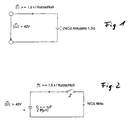
- Fig. 2 shows a possible circuit arrangement for implementation the method according to the invention.
- the shown capacitor assembly has a capacity of about 80 ⁇ Farad to about 250 m Farad (preferably about 7 m Farad) a dielectric strength of about 500 V.
- the nickel-cadmium accumulator connecting with the capacitor arrangement C.
- Switch S can be used as a manually operable circuit breaker or as an electronically controllable power semiconductor switch be designed.
- the charging of the capacitor arrangement C takes place (in a manner not further illustrated) from the Electricity supply via a rectifier.
- a nickel-cadmium storage battery which is charged according to the invention for about 0.2 to 5 msec at 300 V DC with about 10 kA DC, has in later operation at a discharge current of 20 A an increased output voltage by 20 mV (per single cell). This corresponds to a reduced by 1 m ⁇ internal resistance R i .
Abstract
Description
Die vorliegende Erfindung betrifft ein Verfahren zur Verringerung des Innenwiderstandes von wiederaufladbaren Akkumulatoren, insbesondere Nickel-Cadmium-Akkumulatoren. Die Erfindung betrifft jedoch auch die Anwendung des Verfahrens auf andere Arten von Akkumulatoren (Nickel-Metallhydrid, Lithium-Ionen-Akkumulatoren und dergl.). Außerdem betrifft die Erfindung auch derartige Akkumulatoren, die durch das erfindungsgemäße Verfahren erhältlich sind.The present invention relates to a method for reducing the internal resistance of rechargeable batteries, in particular nickel-cadmium accumulators. The invention but also concerns the application of the other types of accumulators (nickel-metal hydride, lithium-ion accumulators and the like). Moreover, the invention relates also such accumulators, by the inventive Procedures are available.
Um die Leistungsfähigkeit von wiederaufladbaren Akkumulatoren zu steigern sind unterschiedliche Verfahren im Stand der Technik bekannt. Die meisten Verfahren beruhen darauf, den Ladestrom oder die Ladespannung beim Ladevorgang des Akkumulators zeitlich und betragsmäßig zu steuern. Außerdem wird durch spezielle Entladegeräte die vollständige Entladung des Akkumulators vor dessen Wiederaufladen sichergestellt.To the performance of rechargeable batteries To increase are different procedures in the state of Technique known. Most procedures are based on the Charging current or the charging voltage during the charging process of the accumulator to control time and amount. In addition, will by special unloading devices the complete discharge of the Accumulator before recharging ensured.
Allerdings ist all diesen Verfahren und Vorgehensweisen zur Behandlung von wiederaufladbaren Akkumulatoren gemeinsam, daß die Akkumulatoren mit relativ niedrigen Spannungen und Strömen aufgeladen werden.However, all these procedures and procedures are for Treatment of rechargeable batteries in common that the accumulators with relatively low voltages and currents to be charged.
Dem gegenüber liegt der Erfindung die Aufgabe zugrunde die Leistungsfähigkeit der Akkumulatoren an sich zu steigern.In contrast, the invention is the object of the To increase the efficiency of the accumulators per se.
Dazu macht sich die Erfindung die überraschende Erkenntnis zunutze, daß es möglich ist, den Innenwiderstand von Akkumulatoren zu senken. For this purpose, the invention makes the surprising finding make use of the fact that it is possible the internal resistance of accumulators to lower.
Die CH-A-677 560 beschreibt ein Verfahren zum Beseitigen von inneren Kurzschlüssen in Akkumulatorzellen. Damit wird der Innenwiderstand des Akkumulators effektiv erhöht. Diese inneren Kurzschlüsse bestehen aus makroskopischen Metallbrücken, die durch elektrolytische Vorgänge im Inneren des Akkumulators gebildet werden. Die Metallbrücke wird durch das Aufprägen eines Stromstoßes aufgelöst, dessen Dauer im Bereich von Millisekunden und dessen Stärke im Bereich des 10- bis 100-fachen des Ladestroms der Akkumulatorzelle gewählt wird.CH-A-677 560 describes a method for eliminating internal short circuits in accumulator cells. This will be the Internal resistance of the accumulator effectively increased. This inner Short circuits consist of macroscopic metal bridges, the by electrolytic processes inside the accumulator be formed. The metal bridge is made by imposing a Power surge resolved, whose duration is in the range of milliseconds and its strength in the range of 10 to 100 times the Charging current of the battery cell is selected.
Erfindungsgemäß werden die Pole des fabrikneuen Akkumulators mit einer elektrischen Energiequelle verbunden, die zur Abgabe einer elektrischen Energie von wenigstens dem 40-fachen Produkt aus betragsmäßigem Kurzschlußstrom und betragsmäßiger Nennspannung eines unbehandelten Akkumulators eingerichtet ist. Gemäß einer bevorzugten Ausführungsform des erfindungsgemäßen Ver-fahrens ist die Energiequelle eine Gleichspannungsquelle, deren positiver Anschluß mit der Anode des Akkumulators, und deren negativer Anschluß mit der Kathode des Akkumulators verbunden ist. Es ist jedoch auch möglich, die Polung umzudrehen, so daß der positive Anschluß mit der Kathode des Akkumulators und deren negativer Anschluß mit der Anode des Akkumulators verbunden ist. Alternativ dazu kann die Energiequelle auch eine Wechselspannungsquelle sein.According to the invention the poles of the brand new accumulator with an electrical energy source connected to the delivery of a electrical energy of at least 40 times the product absolute short-circuit current and rated voltage an untreated accumulator is set up. According to one preferred embodiment of the process according to the invention Ver is the source of energy is a DC source whose positive Connection with the anode of the accumulator, and its negative Connection is connected to the cathode of the accumulator. It is but also possible to turn the polarity so that the positive Connection to the cathode of the accumulator and its negative Connection is connected to the anode of the accumulator. alternative For this purpose, the energy source can also be an AC voltage source be.
Erfindungsgemäß wird die Energiequelle wenigstens eine Millisekunde mit dem Akkumulator verbunden.According to the invention, the energy source is at least one millisecond connected to the accumulator.
Es ist auch möglich, die Energiequelle wiederholt aus- und einzuschalten, so daß der Akkumulator mehrfach mit der elektrischen Energie gespeist wird.It is also possible to turn the power source off and on repeatedly, so that the accumulator several times with the electric Energy is fed.
Vorzugsweise ist die Energiequelle zur Abgabe wenigstens des 1,5-fachen Kurzschlußstroms und der etwa 30-fachen Nennspannung des Akkumulators eingerichtet. Zur Verbesserung des erfindungsgemäBen Preferably, the energy source for delivery is at least 1.5 times Short-circuit current and about 30 times the rated voltage of Accumulator set up. To improve the erfindungsgemäBen
Effektes ist die Energiequelle zur Abgabe des wenigstens 1,5-fachen Kurzschlußstroms und der etwa 40-fachen Nennspannung des Akkumulators eingerichtet. Gemäß einer derzeit besonders bevorzugten Ausführungsform ist die Energiequelle zur Abgabe wenigstens des 60-fachen KurzschluBstroms und etwa der 40-fachen Nennspannung eines Akkumulators mit sechs einzelnen Zellen eingerichtet. Für einen Nickel- Cadmium-Akkumulator mit einer Nennspannung von 7,2 V und einem Kurzschlußstrom von etwa 150 A bedeutet dies etwa 300 V Gleichspannung mit etwa 10 kA.Effect is the energy source for the delivery of at least 1.5 times Short-circuit current and about 40 times the rated voltage of Accumulator set up. According to a currently most preferred Embodiment is the energy source for delivery at least 60 times the short-circuit current and about 40 times the rated voltage an accumulator with six individual cells set up. For a nickel-cadmium accumulator with a rated voltage of 7.2V and a short circuit current of about 150A, this means about 300 V DC with about 10 kA.
Vorzugsweise wird die Energiequelle ca. 1µsec mit dem Akkumulator verbunden.Preferably, the power source is about 1μsec with the accumulator connected.
Die Spannung bzw. der Strom kann erhöht werden, urn den gewünschten
Effekt auf Verringerung des Innenwiderstandes zu verstärken.
Bei Problemen mit der Erwärmung des Akkumulators bei dessen Behandlung
kann dieser entsprechend gekühlt werden.The voltage or current can be increased to increase the desired effect on reducing the internal resistance.
In case of problems with the heating of the accumulator during its treatment, it can be cooled accordingly.
Vorzugsweise geschieht dies durch Eintauchen in eine Flüssigkeit (Öl, Frigen, flüssiger Stickstoff oder dergl.).Preferably, this is done by immersion in a liquid (Oil, Frigen, liquid nitrogen or the like).
Vorzugsweise wird die Energiequelle wenigstens 2 msec mit dem Akkumulator verbunden. Um eine unerwünschte oder nachteilige Erwärmung des Akkumulators zu verhindern, kann neben der vorstehend erwähnten Kühlung des Akkumulators die Energiequelle auch wiederholt abwechselnd ein- und ausgeschaltet werden, um so die Behandlung des Akkumulators in mehrere zeitlich aufeinanderfolgende Abschnitte zu verteilen. Eine gepulste Behandlung des Akkumulators mit 2 bis 200 Impulsen von jeweils etwa 1 µsec bis 2,5 msec Dauer führt auch zu dem erfindungsgemäB gewünschten Ergebnis.Preferably, the energy source is at least 2 msec with the Accumulator connected. To an undesirable or adverse warming to prevent the accumulator, in addition to the above mentioned cooling the accumulator, the power source also repeated alternately turned on and off, so as to the treatment of the accumulator in several temporally successive Distribute sections. A pulsed treatment of the accumulator with 2 to 200 pulses each of about 1 μsec to 2.5 msec Duration also leads to the result desired according to the invention.
Erfindungsgemäß kann entweder jede einzelne Zelle des Akkumulators (ggf. auch vor der Montage mehrerer einzelner Akkumulatorzellen zu einem Akkutnulatorpaket) gemäß dem vorstehenden Verfahren behandelt werden, oder ein montiertes Akkumulatorpaket bestehend aus mehreren einzelnen Akkumulatorzellen wird nach dem Zusammenbau behandelt. In letzterem Fall wird, je nach dem, ob es sich um eine Parallelschaltung und/oder eine Serienschaltung aus einzelnen Akkumulatorzellen handelt, der Strom und/oder die Spannung entsprechend der Anzahl der Zellen erhöht.According to the invention, either each individual cell of the accumulator (If necessary, before installing several individual battery cells to a battery pack package) according to the above method treated or a mounted accumulator package consisting of several individual accumulator cells is after the Assembly handled. In the latter case, depending on if it is is a parallel connection and / or a series connection individual accumulator cells, the current and / or the voltage increased according to the number of cells.
Gute Ergebnisse werden mit dem erfindungsgemäßen Verfahren auch dann erzielt, wenn Akkumulatoren mit dem erfindungsgemäßen Verfahren behandelt werden, die noch nicht mehr als etwa 10, vorzugsweise 2-3 Lade- und Entladevorgängen unterworfen wurden.Good results are also achieved with the method according to the invention achieved when accumulators with the inventive Procedures that are not more than about 10, preferably 2-3 charging and discharging were subjected.
Eine zur Durchführung des Verfahrens geeignete Energiequelle liefert die notwendigen hohen Ströme und Spannungen für die gewünschten Zeitspannen indem sie eine Kondensatoranordnung aufweist, deren Kapazität und Spannungsfestigkeit so gewählt sind, daB sie die elektrische Energie (für die kurze Zeitspanne) an den Akkumulator abgeben kann. Da sich eine Kondensatoranordnung C über einen Widerstand R (hier den Innenwiderstand des Akkumulators) definiert entlädt, kann der dem Akkumulator zugeführte Energieinhalt sehr einfach und zeitlich definiert festgelegt werden (Zeitkonstante τ = R•C). Alternativ dazu besteht jedoch auch die Möglichkeit, mit Hilfe geeigneter Halbleiterschalter und einer entsprechenden Ansteuerschaltung die Energie aus dem Stromnetz direkt zu entnehmen.An energy source suitable for carrying out the process provides the necessary high currents and voltages for the desired periods of time by having a capacitor arrangement has, whose capacity and dielectric strength chosen are that they have the electrical energy (for the short span of time) can deliver to the accumulator. As is a capacitor arrangement C via a resistor R (here the internal resistance of the Accumulator) discharges, which can the accumulator supplied energy content very simple and timely defined be fixed (time constant τ = R • C). Alternatively However, there is also the possibility of using appropriate Semiconductor switch and a corresponding drive circuit the To take energy directly from the power grid.
Weitere Eigenschaften, Vorteile und Merkmale der Erfindung werden anhand der nachstehenden Beschreibung eines derzeit bevorzugten Ausführungsbeispiels erläutert.
- Fig. 1
- zeigt ein Prinzipschaltbild, gemäß dem ein Akkumulator mit einer Energiequelle verbunden wird.
- Fig. 2
- zeigt einen Prinzipschaltplan einer erfindungsgemäßen Energiequelle zur Durchführung des erfindungsgemäßen Verfahrens.
- Fig. 1
- shows a schematic diagram according to which an accumulator is connected to a power source.
- Fig. 2
- shows a schematic diagram of an energy source according to the invention for carrying out the method according to the invention.
Wie in Fig. 1 gezeigt, wird eine Nickel-Cadmium-Akkumulatorzelle (mit einer Nennspannung von 1,2 V mit einer Energiequelle verbunden, die eine betragsmäßige Spannung von wenigstens 42 V und einem betragsmäßigem Strom von wenigstens dem 1,5-fachen Kurzschlußstrom IK abzugeben in der Lage ist. Versuche haben gezeigt, daß der erfindungsgemäße Effekt der Verringerung des Innenwiderstands der Akkumulatorzelle sich bei etwa 60 V Gleichspannung und etwa 225 A Gleichstrom einstellt, wenn diese Energie (13,5 kW) für etwa 2 msec an die Nickel-Cadmium-Zelle angelegt wird. Gemäß einer derzeit bevorzugten Ausführungsvariante werden 300 V Gleichspannung mit etwa 10 kA Gleichstrom für 2 msec an die Nickel-Cadmium-Zelle angelegt.As shown in Fig. 1, a nickel-cadmium storage battery (rated at 1.2 V) is connected to a power source having an absolute voltage of at least 42 V and an absolute current of at least 1.5 times the short circuit current I to give K is capable. experiments have shown that the effect of the invention the reduction is established in the internal resistance of the battery cell at about 60 volts DC and about 225 A direct current, when this energy (13.5 kW) for about 2 msec to the nickel According to a presently preferred embodiment, 300 V DC of approximately 10 kA DC is applied to the nickel-cadmium cell for 2 msec.
Fig. 2 zeigt eine mögliche Schaltungsanordnung zur Durchführung des erfindungsgemäßen Verfahrens. Um den für die erfindungsgemäße Behandlung des Akkumulators erforderlichen Strom mit der wünschenswert hohen Spannung bereitzustellen, hat die gezeigte Kondensatoranordnung eine Kapazität von etwa 80 µFarad bis etwa 250 mFarad (vorzugsweise etwa 7 mFarad) bei einer Spannungsfestigkeit von ca. 500 V. Der den Nickel-Cadmium-Akkumulator mit der Kondensatoranordnung C verbindende Schalter S kann als manuell betätigbarer Leistungsschalter oder als elektronisch ansteuerbarer Leistungshalbleiterschalter ausgestaltet sein. Die Aufladung der Kondensatoranordnung C erfolgt (in nicht weiter veranschaulichter Weise) aus dem Stromnetz über einen Gleichrichter.Fig. 2 shows a possible circuit arrangement for implementation the method according to the invention. To the for the invention Treatment of the battery required electricity with the desirable high voltage, the shown capacitor assembly has a capacity of about 80 μ Farad to about 250 m Farad (preferably about 7 m Farad) a dielectric strength of about 500 V. The nickel-cadmium accumulator connecting with the capacitor arrangement C. Switch S can be used as a manually operable circuit breaker or as an electronically controllable power semiconductor switch be designed. The charging of the capacitor arrangement C takes place (in a manner not further illustrated) from the Electricity supply via a rectifier.
Ein Nickel-Cadmium-Akkumulator, der erfindungsgemäß für 0,2 bis 5 msec bei 300 V Gleichspannung mit etwa 10 kA Gleichstrom beaufschlagt wird, hat im späteren Betrieb bei einem Entladestrom von 20 A eine um 20 mV erhöhte Ausgangsspannung (pro einzelner Zelle). Dies entspricht einem um 1 mΩ verringerten Innenwiderstand Ri. A nickel-cadmium storage battery, which is charged according to the invention for about 0.2 to 5 msec at 300 V DC with about 10 kA DC, has in later operation at a discharge current of 20 A an increased output voltage by 20 mV (per single cell). This corresponds to a reduced by 1 mΩ internal resistance R i .
Abwandlungen des erfindungsgemäßen Verfahrens (Behandlung mit höherem Strom, höherer Spannung, größerer Zeitdauer der Behandlung oder gepulster Beaufschlagung des Akkumulators mit der elektrischen Energie) sind in der oben beschriebenen Weise möglich und durch den Erfindungsgedanken umfaßt. Auch die erfindungsgemäße Schaltung (Fig. 2) kann durch eine andere Energiequelle ersetzt werden ohne den Erfindungsgedanken zu verlassen, solange die Energiequelle die Energie in der erfindungsgemäß beschriebenen Weise liefert.Modifications of the method according to the invention (treatment with higher current, higher voltage, longer duration of treatment or pulsed loading of the accumulator with the electrical energy) are in the manner described above possible and encompassed by the spirit of the invention. Also the inventive circuit (Fig. 2) can by another Energy source to be replaced without the inventive idea leave as long as the energy source the energy in the invention described manner.
Claims (14)
- Method for reducing the internal resistance (Ri) of rechargeable batteries, in particular of nickel cadmium rechargeable batteries, in which an electrical power source is connected to the poles (+/-) of the rechargeable battery, which electrical power source is designed to emit an electrical power equivalent to at least 40 times the product of the magnitude of the short-circuit current (IK) and of the magnitude of the rated voltage of an untreated rechargeable battery, and with the power being applied to the rechargeable battery for a predetermined time period.
- Method according to Claim 1, in which the power source is a DC voltage source, whose positive connection (+) is connected to the anode of the rechargeable battery, and whose negative connection (-) is connected to the cathode of the rechargeable battery.
- The method as claimed in Claim 1, in which the power source is a DC voltage source, whose positive connection is connected to the cathode of the rechargeable battery and whose negative connection is connected to the anode of the rechargeable battery.
- Method according to Claim 1, in which the power source is an AC voltage source with two output connections, one of which is respectively connected to the anode and to the cathode of the rechargeable battery.
- Method according to one of Claims 1 to 4, in which the power source is connected to the rechargeable battery for at least one microsecond (1 µs) in order to apply the electrical power to it.
- Method according to Claim 5, in which the power source is alternately and repeatedly connected and disconnected.
- Method according to one of Claims 1 to 4, characterized in that the power source is designed to admit at least 1.5 times the short-circuit current (IK) and 40 to 30 times the rated voltage of the rechargeable battery.
- Method according to Claim 7, in which the power source is designed to emit at least 1.5 times the short-circuit current (IK) and 40 times the rated voltage of the rechargeable battery.
- Method according to Claim 8, in which the power source is designed to emit 60 times the short-circuit current and 300 times the rated voltage of the rechargeable battery.
- Method according to one of Claims 7 to 9, in which the power source is connected to the rechargeable battery for at least 1 µs in order to apply the electrical power to it.
- Method according to Claim 10, characterized in that the power source is alternately and repeatedly connected and disconnected.
- Method according to one of Claims 1 to 11, in which each cell in a rechargeable battery which has two or more cells is treated individually.
- Method according to one of Claims 1 to 12, in which two or more cells are treated in parallel, with the current being increased to correspond to the number of cells.
- Method according to one of Claims 1 to 12, in which two or more cells are treated connected in series, with the voltage being increased to correspond to the number of cells.
Applications Claiming Priority (1)
| Application Number | Priority Date | Filing Date | Title |
|---|---|---|---|
| PCT/EP1996/001710 WO1997040544A1 (en) | 1996-04-24 | 1996-04-24 | Method for reducing the internal resistance of rechargeable batteries |
Publications (2)
| Publication Number | Publication Date |
|---|---|
| EP0835532A1 EP0835532A1 (en) | 1998-04-15 |
| EP0835532B1 true EP0835532B1 (en) | 2005-12-28 |
Family
ID=8166209
Family Applications (1)
| Application Number | Title | Priority Date | Filing Date |
|---|---|---|---|
| EP96914982A Expired - Lifetime EP0835532B1 (en) | 1996-04-24 | 1996-04-24 | Method for reducing the internal resistance of rechargeable batteries |
Country Status (7)
| Country | Link |
|---|---|
| US (1) | US5905363A (en) |
| EP (1) | EP0835532B1 (en) |
| JP (1) | JP3561524B2 (en) |
| KR (1) | KR100397481B1 (en) |
| AU (1) | AU5692296A (en) |
| DE (2) | DE19681411D2 (en) |
| WO (1) | WO1997040544A1 (en) |
Families Citing this family (10)
| Publication number | Priority date | Publication date | Assignee | Title |
|---|---|---|---|---|
| JP3547927B2 (en) * | 1996-07-10 | 2004-07-28 | 三洋電機株式会社 | Alkaline storage battery and method for manufacturing the same |
| US6118251A (en) * | 1999-01-27 | 2000-09-12 | The United States Of America As Represented By The Secretary Of The Army | Battery depassivation and conditioning method and apparatus |
| JP4039792B2 (en) | 1999-08-27 | 2008-01-30 | 三洋電機株式会社 | Storage battery and manufacturing method thereof |
| US6172486B1 (en) * | 1999-09-24 | 2001-01-09 | The United States Of America As Represented By The Secretary Of The Army | Battery life extender with engine heat |
| US6566844B1 (en) | 1999-10-06 | 2003-05-20 | Battery Performance Technologies, Inc. | Method and apparatus for extending the functionality of a battery |
| WO2002035679A1 (en) * | 2000-10-26 | 2002-05-02 | Curtis Henry Dobbie | System and method for charging rechargeable batteries |
| US6469473B1 (en) | 2001-03-16 | 2002-10-22 | Battery Performance Technologies, Inc. | Method and apparatus for using pulse current to extend the functionality of a battery |
| US8623301B1 (en) | 2008-04-09 | 2014-01-07 | C3 International, Llc | Solid oxide fuel cells, electrolyzers, and sensors, and methods of making and using the same |
| EP2534723A4 (en) | 2010-02-10 | 2015-08-05 | Fcet Inc | Low temperature electrolytes for solid oxide cells having high ionic conductivity |
| WO2015009618A1 (en) | 2013-07-15 | 2015-01-22 | Fcet, Llc | Low temperature solid oxide cells |
Family Cites Families (8)
| Publication number | Priority date | Publication date | Assignee | Title |
|---|---|---|---|---|
| GB8319187D0 (en) * | 1983-07-15 | 1983-08-17 | Morris N | Dry cell battery re-activator |
| US4829225A (en) * | 1985-10-23 | 1989-05-09 | Electronic Power Devices, Corp. | Rapid battery charger, discharger and conditioner |
| CH677560A5 (en) * | 1989-07-17 | 1991-05-31 | Siemens Ag Albis | Avoidance of short circuits in rechargeable battery cells - having current pulses applied to break down macroscopic metal bridging |
| JP2616077B2 (en) * | 1989-12-27 | 1997-06-04 | 三菱電機株式会社 | Battery activation method and device |
| USRE35643E (en) * | 1990-10-16 | 1997-10-28 | Motor Products International, Inc. | Lead acid battery rejuvenator and charger |
| US5063341A (en) * | 1990-10-16 | 1991-11-05 | Gali Carl E | Lead acid battery rejuvenator and charger |
| JPH0670478A (en) * | 1992-08-20 | 1994-03-11 | Ebatoron:Kk | Method for charging battery by spike-like wave and apparatus thereof |
| DE4308538A1 (en) * | 1993-03-17 | 1994-09-22 | Rotermund Ulli | Method and device for regenerating voltage sources in the form of galvanic elements, in particular primary elements |
-
1996
- 1996-04-24 KR KR1019970709609A patent/KR100397481B1/en not_active IP Right Cessation
- 1996-04-24 JP JP53763397A patent/JP3561524B2/en not_active Expired - Lifetime
- 1996-04-24 DE DE19681411T patent/DE19681411D2/en not_active Expired - Fee Related
- 1996-04-24 WO PCT/EP1996/001710 patent/WO1997040544A1/en active IP Right Grant
- 1996-04-24 US US08/973,841 patent/US5905363A/en not_active Expired - Lifetime
- 1996-04-24 AU AU56922/96A patent/AU5692296A/en not_active Abandoned
- 1996-04-24 DE DE59611318T patent/DE59611318D1/en not_active Expired - Lifetime
- 1996-04-24 EP EP96914982A patent/EP0835532B1/en not_active Expired - Lifetime
Also Published As
| Publication number | Publication date |
|---|---|
| AU5692296A (en) | 1997-11-12 |
| JP3561524B2 (en) | 2004-09-02 |
| DE19681411D2 (en) | 1998-08-20 |
| EP0835532A1 (en) | 1998-04-15 |
| JPH11514135A (en) | 1999-11-30 |
| DE59611318D1 (en) | 2006-02-02 |
| WO1997040544A1 (en) | 1997-10-30 |
| KR100397481B1 (en) | 2003-11-19 |
| US5905363A (en) | 1999-05-18 |
| KR19990028295A (en) | 1999-04-15 |
Similar Documents
| Publication | Publication Date | Title |
|---|---|---|
| EP3373407B1 (en) | Method for operating a modular battery storage system, modular battery storage system and battery management system therefor | |
| EP0835532B1 (en) | Method for reducing the internal resistance of rechargeable batteries | |
| WO2008155209A1 (en) | Battery pack with switch for high-current operation | |
| DE112012003131T5 (en) | Charge control device and charge control method for a secondary battery | |
| DE102015002072A1 (en) | Adjusting charge states of battery cells | |
| WO2009146952A1 (en) | Electrical energy store | |
| EP2862255A2 (en) | Switching device for a battery and corresponding switching method | |
| EP3676933A1 (en) | Device for electropolishing an energy storage device comprising at least one lithium ion cell, charger, and method for operating the charger | |
| DE102008059392A1 (en) | Method and device for charging batteries | |
| EP0616410A2 (en) | Method and device for regenerating voltage sources in the form of primary cells | |
| EP0114871B1 (en) | Method and device for monitoring the each time-charged capacity of accumulators | |
| DE102019117345A1 (en) | Battery system, method for operating a battery system and motor vehicle | |
| DE102019212000A1 (en) | Battery circuit for setting the state of charge of battery elements and a method for operating a battery circuit | |
| DE2928503A1 (en) | Auxiliary battery charger for no break power supply - is for charging individual sections to gassing point to maintain battery performance | |
| EP1250745B1 (en) | Device for regenerating accumulators | |
| DE2521785C3 (en) | Process for the production of a storable lead accumulator | |
| DE102016224005A1 (en) | Electrical energy storage device | |
| DE102018220564A1 (en) | Battery cell, method for heating a battery cell and battery module | |
| DE1922385C3 (en) | Method and circuit arrangement for rapid charging of an electric battery | |
| EP1587202A1 (en) | Method and device for charging a battery | |
| DE102021111865A1 (en) | Mobile energy supply system with optimized energy density | |
| DE656369C (en) | Arrangement for the charging of electrical collector batteries | |
| AT524263A1 (en) | Battery device with switchable battery modules | |
| CN1117409C (en) | Method for reducing internal resisance of rechargeable batteries | |
| DE4338463A1 (en) | Electric powered road vehicle |
Legal Events
| Date | Code | Title | Description |
|---|---|---|---|
| PUAI | Public reference made under article 153(3) epc to a published international application that has entered the european phase |
Free format text: ORIGINAL CODE: 0009012 |
|
| AK | Designated contracting states |
Kind code of ref document: A1 Designated state(s): DE FR GB |
|
| 17P | Request for examination filed |
Effective date: 19991029 |
|
| 17Q | First examination report despatched |
Effective date: 20020214 |
|
| GRAP | Despatch of communication of intention to grant a patent |
Free format text: ORIGINAL CODE: EPIDOSNIGR1 |
|
| GRAS | Grant fee paid |
Free format text: ORIGINAL CODE: EPIDOSNIGR3 |
|
| RAP1 | Party data changed (applicant data changed or rights of an application transferred) |
Owner name: SANYO ELECTRIC CO., LTD. |
|
| GRAA | (expected) grant |
Free format text: ORIGINAL CODE: 0009210 |
|
| AK | Designated contracting states |
Kind code of ref document: B1 Designated state(s): DE FR GB |
|
| REG | Reference to a national code |
Ref country code: GB Ref legal event code: FG4D Free format text: NOT ENGLISH |
|
| REF | Corresponds to: |
Ref document number: 59611318 Country of ref document: DE Date of ref document: 20060202 Kind code of ref document: P |
|
| GBT | Gb: translation of ep patent filed (gb section 77(6)(a)/1977) |
Effective date: 20060322 |
|
| ET | Fr: translation filed | ||
| PLBE | No opposition filed within time limit |
Free format text: ORIGINAL CODE: 0009261 |
|
| STAA | Information on the status of an ep patent application or granted ep patent |
Free format text: STATUS: NO OPPOSITION FILED WITHIN TIME LIMIT |
|
| 26N | No opposition filed |
Effective date: 20060929 |
|
| REG | Reference to a national code |
Ref country code: FR Ref legal event code: PLFP Year of fee payment: 20 |
|
| PGFP | Annual fee paid to national office [announced via postgrant information from national office to epo] |
Ref country code: DE Payment date: 20150422 Year of fee payment: 20 Ref country code: GB Payment date: 20150422 Year of fee payment: 20 |
|
| PGFP | Annual fee paid to national office [announced via postgrant information from national office to epo] |
Ref country code: FR Payment date: 20150408 Year of fee payment: 20 |
|
| REG | Reference to a national code |
Ref country code: DE Ref legal event code: R071 Ref document number: 59611318 Country of ref document: DE |
|
| REG | Reference to a national code |
Ref country code: GB Ref legal event code: PE20 Expiry date: 20160423 |
|
| PG25 | Lapsed in a contracting state [announced via postgrant information from national office to epo] |
Ref country code: GB Free format text: LAPSE BECAUSE OF EXPIRATION OF PROTECTION Effective date: 20160423 |