EP0835372B1 - Zufuhrvorrichtung für gasförmigen brennstoff für eine brennkraftmaschine - Google Patents
Zufuhrvorrichtung für gasförmigen brennstoff für eine brennkraftmaschine Download PDFInfo
- Publication number
- EP0835372B1 EP0835372B1 EP96918922A EP96918922A EP0835372B1 EP 0835372 B1 EP0835372 B1 EP 0835372B1 EP 96918922 A EP96918922 A EP 96918922A EP 96918922 A EP96918922 A EP 96918922A EP 0835372 B1 EP0835372 B1 EP 0835372B1
- Authority
- EP
- European Patent Office
- Prior art keywords
- pressure
- membrane
- pressure regulating
- metering device
- gas
- Prior art date
- Legal status (The legal status is an assumption and is not a legal conclusion. Google has not performed a legal analysis and makes no representation as to the accuracy of the status listed.)
- Expired - Lifetime
Links
- 238000002485 combustion reaction Methods 0.000 title claims abstract description 55
- 239000000446 fuel Substances 0.000 title claims abstract description 26
- 238000001704 evaporation Methods 0.000 claims abstract description 19
- 230000001105 regulatory effect Effects 0.000 claims description 50
- 239000012528 membrane Substances 0.000 claims description 39
- 239000007788 liquid Substances 0.000 claims description 5
- 238000005192 partition Methods 0.000 claims description 4
- 239000007789 gas Substances 0.000 description 63
- 239000000203 mixture Substances 0.000 description 4
- XLYOFNOQVPJJNP-UHFFFAOYSA-N water Substances O XLYOFNOQVPJJNP-UHFFFAOYSA-N 0.000 description 3
- 239000000498 cooling water Substances 0.000 description 2
- 230000003247 decreasing effect Effects 0.000 description 2
- 230000000694 effects Effects 0.000 description 2
- VNWKTOKETHGBQD-UHFFFAOYSA-N methane Chemical compound C VNWKTOKETHGBQD-UHFFFAOYSA-N 0.000 description 2
- 238000013016 damping Methods 0.000 description 1
- 230000008030 elimination Effects 0.000 description 1
- 238000003379 elimination reaction Methods 0.000 description 1
- 230000008020 evaporation Effects 0.000 description 1
- 239000003345 natural gas Substances 0.000 description 1
- 230000000704 physical effect Effects 0.000 description 1
- 239000000523 sample Substances 0.000 description 1
Images
Classifications
-
- F—MECHANICAL ENGINEERING; LIGHTING; HEATING; WEAPONS; BLASTING
- F02—COMBUSTION ENGINES; HOT-GAS OR COMBUSTION-PRODUCT ENGINE PLANTS
- F02M—SUPPLYING COMBUSTION ENGINES IN GENERAL WITH COMBUSTIBLE MIXTURES OR CONSTITUENTS THEREOF
- F02M21/00—Apparatus for supplying engines with non-liquid fuels, e.g. gaseous fuels stored in liquid form
- F02M21/02—Apparatus for supplying engines with non-liquid fuels, e.g. gaseous fuels stored in liquid form for gaseous fuels
- F02M21/06—Apparatus for de-liquefying, e.g. by heating
-
- F—MECHANICAL ENGINEERING; LIGHTING; HEATING; WEAPONS; BLASTING
- F02—COMBUSTION ENGINES; HOT-GAS OR COMBUSTION-PRODUCT ENGINE PLANTS
- F02M—SUPPLYING COMBUSTION ENGINES IN GENERAL WITH COMBUSTIBLE MIXTURES OR CONSTITUENTS THEREOF
- F02M21/00—Apparatus for supplying engines with non-liquid fuels, e.g. gaseous fuels stored in liquid form
- F02M21/02—Apparatus for supplying engines with non-liquid fuels, e.g. gaseous fuels stored in liquid form for gaseous fuels
- F02M21/0218—Details on the gaseous fuel supply system, e.g. tanks, valves, pipes, pumps, rails, injectors or mixers
- F02M21/023—Valves; Pressure or flow regulators in the fuel supply or return system
- F02M21/0239—Pressure or flow regulators therefor
-
- F—MECHANICAL ENGINEERING; LIGHTING; HEATING; WEAPONS; BLASTING
- F02—COMBUSTION ENGINES; HOT-GAS OR COMBUSTION-PRODUCT ENGINE PLANTS
- F02M—SUPPLYING COMBUSTION ENGINES IN GENERAL WITH COMBUSTIBLE MIXTURES OR CONSTITUENTS THEREOF
- F02M21/00—Apparatus for supplying engines with non-liquid fuels, e.g. gaseous fuels stored in liquid form
- F02M21/02—Apparatus for supplying engines with non-liquid fuels, e.g. gaseous fuels stored in liquid form for gaseous fuels
- F02M21/0218—Details on the gaseous fuel supply system, e.g. tanks, valves, pipes, pumps, rails, injectors or mixers
- F02M21/0248—Injectors
- F02M21/0278—Port fuel injectors for single or multipoint injection into the air intake system
-
- F—MECHANICAL ENGINEERING; LIGHTING; HEATING; WEAPONS; BLASTING
- F02—COMBUSTION ENGINES; HOT-GAS OR COMBUSTION-PRODUCT ENGINE PLANTS
- F02M—SUPPLYING COMBUSTION ENGINES IN GENERAL WITH COMBUSTIBLE MIXTURES OR CONSTITUENTS THEREOF
- F02M21/00—Apparatus for supplying engines with non-liquid fuels, e.g. gaseous fuels stored in liquid form
- F02M21/02—Apparatus for supplying engines with non-liquid fuels, e.g. gaseous fuels stored in liquid form for gaseous fuels
- F02M21/0218—Details on the gaseous fuel supply system, e.g. tanks, valves, pipes, pumps, rails, injectors or mixers
- F02M21/0248—Injectors
- F02M21/0281—Adapters, sockets or the like to mount injection valves onto engines; Fuel guiding passages between injectors and the air intake system or the combustion chamber
-
- Y—GENERAL TAGGING OF NEW TECHNOLOGICAL DEVELOPMENTS; GENERAL TAGGING OF CROSS-SECTIONAL TECHNOLOGIES SPANNING OVER SEVERAL SECTIONS OF THE IPC; TECHNICAL SUBJECTS COVERED BY FORMER USPC CROSS-REFERENCE ART COLLECTIONS [XRACs] AND DIGESTS
- Y02—TECHNOLOGIES OR APPLICATIONS FOR MITIGATION OR ADAPTATION AGAINST CLIMATE CHANGE
- Y02T—CLIMATE CHANGE MITIGATION TECHNOLOGIES RELATED TO TRANSPORTATION
- Y02T10/00—Road transport of goods or passengers
- Y02T10/10—Internal combustion engine [ICE] based vehicles
- Y02T10/30—Use of alternative fuels, e.g. biofuels
-
- Y—GENERAL TAGGING OF NEW TECHNOLOGICAL DEVELOPMENTS; GENERAL TAGGING OF CROSS-SECTIONAL TECHNOLOGIES SPANNING OVER SEVERAL SECTIONS OF THE IPC; TECHNICAL SUBJECTS COVERED BY FORMER USPC CROSS-REFERENCE ART COLLECTIONS [XRACs] AND DIGESTS
- Y10—TECHNICAL SUBJECTS COVERED BY FORMER USPC
- Y10S—TECHNICAL SUBJECTS COVERED BY FORMER USPC CROSS-REFERENCE ART COLLECTIONS [XRACs] AND DIGESTS
- Y10S123/00—Internal-combustion engines
- Y10S123/12—Hydrogen
Definitions
- a device suitable for supplying a gaseous fuel to an internal combustion engine, as well as an evaporator, a metering device, a processor and a pressure regulating unit suitable for use in such a device as well as an evaporator, a metering device, a processor and a pressure regulating unit suitable for use in such a device.
- the invention relates to a device suitable for supplying a gaseous fuel to an internal combustion engine comprising combustion chambers, which device is provided with an evaporator and with a metering device, said metering device on an inlet side being in communication with an evaporating chamber disposed within said evaporator, and on an outlet side being provided with a main pipe, said main pipe after said metering device branching into a number of pipes connected to the individual combustion chambers.
- the invention furthermore relates to an evaporator, a metering device, a processor and a pressure regulating unit suitable for use in such a device.
- a pressure modulator 23 located in the main pipe.
- the main pipe is connected to a branching device 29 in which the main pipe branches in a number of pipes 30 connected to the individual combustion chambers.
- the function of the pressure modulator 23 is to prevent that the pressure fluctuations in the inlet manifold influence the stability of the pressure controller/evaporator. Hereby deviations between the desired total gas flow and the actual total gas flow are prevented. Such variations could obviously occur as a result of variation in the pressure line.
- the object of the invention is to provide a relatively simple device, by means of which gas can be supplied to an internal combustion engine in a metered manner whereby an optimalisation of the equal distribution of the total gas flow over the different cylinders of the combustion engine is obtained.
- each pipe is provided with a fixed predetermined local constriction, across which at least 85% of the pressure drop from the division of the main pipe into the individual pipes to the combustion chambers takes place, whereby the differences in the flow resistances of the local constrictions of the individual pipes are 5% at most.
- the exhaust gases of the various combustion chambers will have substantially the same composition.
- US-A-4,386,593 describes a device with adjustable valves 30 in each hose.
- US-A-3,799,124 in practise it will hardly be possible to realise an adjustment which meets the requirements that are set by the latest regulations with respect to emission. Furthermore such adjustment is only possible with special test equipment and is very time consuming.
- One embodiment of the device according to the invention is characterized in that the outlet side of the metering device is connected to a pressure regulating chamber disposed within the evaporator, which pressure regulating chamber is separated from the evaporating chamber by a movable membrane, whereby the supply of liquid gas to the evaporating chamber can be regulated by means of said membrane.
- the membrane may be spring-biased. As long as the (possible) spring pressure and the gas pressure in the pressure regulating chamber are greater than the gas pressure in the evaporating chamber, the supply of for example liquid gas to the evaporating chamber will remain open. As soon as the pressures in both chambers are equal, the gas supply is shut off. When the pressure after the local constrictions increases, the pressure before the local constriction will also increase. As soon as this pressure becomes greater than the pressure after the metering device, the pressure after the metering device will increase as well.
- Another device is characterized in that the metering device is provided with a controllable passage, whereby the width of said passage may be controlled in dependence on a petrol fuel requirement of the internal combustion engine present in a processor.
- Another embodiment of the device according to the invention is characterized in that the width of the passage can be adjusted for differences between the use of gas and the use of petrol as the fuel for the combustion engine.
- the gas supply can be adjusted for differences such as cold start mixture enrichment and full load mixture enrichment, which are necessary when the engine runs on petrol and which are not necessary when the engine runs on gas.
- cold start mixture enrichment and full load mixture enrichment which are necessary when the engine runs on petrol and which are not necessary when the engine runs on gas.
- the engine is fuelled by gas, adjustments need to be made for the density of the gas in dependence on the temperature and pressure.
- Yet another embodiment of the device is characterized in that the device is provided with a pressure regulating unit, which is disposed between said metering device and said local constrictions.
- the pressure drop across the metering device can be kept relatively small by means of the pressure regulating unit, as a result of which the metering device does not need to satisfy relatively heavy demands of accuracy.
- the loads within the metering device are relatively low as a result of a relatively small pressure drop, which enables a quick and/or more inexpensive operation of the metering device.
- the pressure regulating unit is provided with an inlet, an outlet and a flow channel connected to said inlet and said outlet, in which flow channel a valve is movably provided so as to be capable of closing a passage between said inlet and said flow channel, said valve with a first end being connected to a first membrane, which constitutes a partition between the inlet and the flow channel on the one hand and a first pressure regulating chamber on the other hand, and with a second end being positioned opposite a second membrane, which extends parallel to said first membrane, said second membrane constituting a partition between said flow channel and a second pressure regulating chamber, whereby said valve can be pressed in the direction of said first membrane by means of said second membrane.
- the second membrane When the pressure in the flow channel is lower than in the second pressure regulating chamber, the second membrane abuts against the second end of the valve and the valve is pressed in the direction of the first membrane. As a result of the pressure in the first regulating chamber, however, the valve is also pressed in the direction of the second membrane by means of the first membrane.
- the membranes When the pressure in the flow channel is higher than in the second pressure regulating chamber, the membranes are moved away from each other, whereby the second membrane will be positioned clear of the second end of the valve.
- the first membrane is pressed in the direction of the first pressure regulating chamber together with the valve, as a result of which the opening of the valve is facilitated.
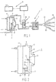
- Figure 1 shows a device 1 for supplying gas to combustion chambers of an internal combustion engine (not shown).
- the device 1 comprises an evaporator 3, a metering device 5, a pressure regulating unit 7 and a processor 9.
- the evaporator 3 ( Figure 2) comprises a water chamber 11, which is connected to a cooling water circuit (not shown) of the internal combustion engine, and an evaporating chamber 13 disposed adjacent to the water chamber 11, said evaporating chamber on one side being connected to a gas supply 15 and on the other side being connected to an input side of metering device 5.
- Evaporator 3 furthermore comprises a pressure regulating chamber 17, which is separated from evaporating chamber 13 by means of a membrane 19.
- Membrane 19 is connected to a first end 21 of a lever 23, which pivots about a pivot point 25.
- the second end 27 of lever 23 is provided with a valve 29, by means of which the gas supply 15 can be closed.
- a spring 31 is disposed within pressure regulating chamber 17, which spring presses membrane 19 in the direction of evaporating chamber 13.
- the pressure regulating chamber 17 is connected to an output side of metering device 5.
- Valve 29 will remain open as long as the spring pressure and the gas pressure in pressure regulating chamber 17 together are greater than the gas pressure in evaporating chamber 13.
- lever 23 will tilt about pivot point 25 to a position in which valve 29 shuts off gas supply 15.
- Metering device 5 ( Figure 3) comprises an inlet side 32 and an outlet side 33 and a cylindrical chamber 35 therebetween, in which chamber a conical plunger 37 is movable with respect to a ring 41, for example by means of a stepping motor 39.
- the width of a passage 43 between plunger 37 and ring 41 is increased or decreased by moving conical plunger 37, as a result of which the amount of gas that flows through metering device 5 is increased or decreased.
- the pressure regulating unit 7 ( Figure 4) comprises an inlet 45, an outlet 47 and a flow channel 49 therebetween.
- a valve 51 is capable of movement within flow channel 49, by means of which valve the communication between inlet 45 and outlet 47 can be shut off.
- Valve 51 is connected to a first membrane 53 with one end and is with a second end positioned opposite a second membrane 55 extending parallel to first membrane 53.
- Pressure regulating chambers 57, 59 are disposed on a side of membranes 53, 55 facing away from said valve, said pressure regulating chambers being connected to atmospheric pressure.
- a spring 61 is disposed within pressure regulating chamber 57, which spring presses against membrane 53. Gas which enters pressure regulating unit 7 via inlet 45 exerts a pressure on membrane 53.
- valve 51 When this pressure is greater than the force exerted by spring 61 and said atmospheric pressure, valve 51 will be opened and gas will flow out of outlet 47 through flow channel 49.
- a gas pressure in outlet 47 which is lower than the pressure in pressure regulating chambers 57, 59 will not have an influence on the movement of valve 51, since the gas pressure acts on the same area both in the direction of membrane 53 and in the direction of membrane 55 positioned opposite thereto, and thus also in two opposite directions on valve 51.
- the pressure in outlet 47 is higher than the pressure in pressure regulating chambers 57, 59, the second membrane 55 is moved away from the second end of valve 51 and the first membrane 53 is moved, together with valve 51, in the direction of the first pressure regulating chamber 57, as a result of which the opening of the valve is simplified.
- Valve 51 and flow channel 49 may be relatively large, which enables a good flow-through.
- Outlet 47 of pressure regulating unit 7 is connected to pipes 63, which are at another end connected to combustion chambers (not shown) of the internal combustion engine.
- Pipes 63 are provided with identical local constrictions 65 right before the inlet manifold. Pipe 63 has a diameter of 5 mm and local constriction 65 has a diameter of 2 mm ⁇ 0.05 mm and a length of 2 mm, for example.
- Another example concerns a pipe having a diameter D of 4 mm and a length L of 30 cm, the local constriction has a diameter d of 2 mm with a tolerance of 0.05 mm.
- the mass flow m is 1 g/second, whilst the specific mass ⁇ equals 2 kg/m 2 .
- the flow resistance ⁇ equals 0.016.
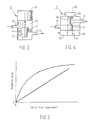
- Processor 9 of device 1 comprises a gas management system 69, wherein a number of data are taken over from a petrol motor management system 67 known per se, which data is processed to produce a particular position of plunger 37 and thus a particular width of the passage 43 and the gas supply to the internal combustion engine.
- a petrol motor management system 67 known per se
- the petrol fuel requirement is taken over from said petrol motor management system 67, which is translated into a particular position of plunger 37, for example as shown in Figure 5.
- a lambda value is determined by means of petrol motor management system 67, which value is a measure for an efficient combustion.
- the operation of the device is as follows.
- Gas from a gas tank for example LPG or natural gas, is supplied to evaporating chamber 13 at a relatively high pressure and/or in liquid form.
- the hot cooling water in water chamber 11 heats and possibly evaporates the gas, which is supplied to metering device 5 under pressure.
- plunger 37 is moved to a particular position, for example by means of stepping motor 39, thus determining the width of passage 43.
- the gas flows to pressure regulator 7, and valve 51 is opened as soon as the gas pressure in the inlet is greater than the atmospheric pressure and the spring pressure in pressure regulating chamber 57.
- the gas then flows to the combustion chambers through pipes 63 and the identical local constrictions 65.
- valve 51 will alternately be open or be closed, depending on the pressure in inlet 45.
- the pressure before the combustion chambers will run up, and thus the pressure before flow resistance 65 may run up to such a degree that the pressure in outlet 47 is greater than the pressure in pressure regulating chamber 57, which pressure is made up of the spring pressure 61 and the atmospheric pressure.
- the pressure in inlet 45 will also increase to a level higher than the pressure in pressure regulating chamber 57, as a result of which valve 51 will be permanently open.
- the pressure in inlet 45 is also detected in pressure regulating chamber 17 of evaporator 3, as a result of which valve 29 is opened and gas will flow to evaporating chamber 13.
- the gas pressure in the entire device 1 will thereby run up to such a degree that the pressure across the metering device will remain constant, as a result of which a sufficient amount of gas will flow to the combustion chambers.
- the pressure before the metering device 5 will be about 1.5 bar.
- the constant pressure drop across metering device 5, which is determined in particular by spring 31, amounts to about 0.4 bar. Because of the relatively small constant pressure drop across metering device 5, said metering device 5 does not need to be manufactured with great precision in order to be able to ensure an accurate metering after all.
- the first adjustment concerns a difference between petrol and gas as the fuel being used.
- the second adjustment concerns the elimination of an adjustment made in the petrol motor management system with regard to the petrol fuel requirement, which adjustment is not necessary for gas.
- the gas management system 69 determines the gas supply on the basis of the petrol fuel requirement determined by petrol motor management system 67. This implies that adjustments are automatically made for all influencing factors.
- the petrol fuel requirement may be derived from the petrol engine motor management system 67 via a databus or a control signal (duty cycle) from one or more petrol injectors.
- pressure regulating unit 7 is provided with a number of outlets 47, which number corresponds with the number of combustion chambers.
- plunger 37 may also be polynomially conical or otherwise, whereby a relatively small movement of the plunger has a larger or smaller influence on the gas supply, depending on the position of plunger 37.
- the gas is not supplied directly near the combustion chambers, but first led to the throttle valve via one pipe 63 and mixed with air before being supplied to the combustion chambers.
- Evaporator 3 pressure regulating unit 7, gas management system 69 and the feedback from the outlet side of metering device 5 to evaporator 3 may also be used here.
Landscapes
- Engineering & Computer Science (AREA)
- Chemical & Material Sciences (AREA)
- Chemical Kinetics & Catalysis (AREA)
- General Chemical & Material Sciences (AREA)
- Oil, Petroleum & Natural Gas (AREA)
- Combustion & Propulsion (AREA)
- Mechanical Engineering (AREA)
- General Engineering & Computer Science (AREA)
- Output Control And Ontrol Of Special Type Engine (AREA)
- Fuel-Injection Apparatus (AREA)
- Feeding And Controlling Fuel (AREA)
Claims (11)
- Vorrichtung (1) geeignet für die Zufuhr eines gasförmigen Kraftstoffs zu einem Verbrennungsmotor welcher Brennräume umfaßt; die genannte Vorrichtung ist versehen mit einem Verdampfer (3) und mit einer Dosiereinrichtung (5), wobei die genannte Dosiereinrichtung (5) an einer Einlaßseite (32) mit einer Verdampferkammer (13) verbunden ist, die innerhalb des genannten Verdampfers (3) angeordnet ist, und an einer Auslaßseite (33) mit einem Hauptrohr versehen ist und sich das genannte Hauptrohr nach der genannten Dosiereinrichtung (5) in eine Reihe von Rohren (63) verzweigt, die mit den einzelnen Brennräumen verbunden sind, dadurch gekennzeichnet, daß jedes Rohr (63) mit einer festen vorher festgelegten lokalen Verengung (65) versehen ist, über die mindestens 85 % des Druckabfalls von der Aufteilung des Hauptrohrs in die einzelnen Rohre (63) zu den Brennräumen erfolgt, wobei die Unterschiede in den Strömungswiderständen der lokalen Verengungen (65) der einzelnen Rohre (63) höchstens 5 % betragen.
- Vorrichtung nach Anspruch 1, dadurch gekennzeichnet, daß die Länge der genannten lokalen Verengung (65) höchstens 15 mm beträgt.
- Vorrichtung nach einem der vorstehenden Ansprüche, dadurch gekennzeichnet, daß die Auslaßseite der Dosiereinrichtung (5) mit einer Druckregelkammer (17) verbunden ist, die innerhalb des Verdampfers (3) angeordnet ist, wobei die Druckregelkammer (17) von der Verdampferkammer (13) durch eine bewegliche Membran (19) getrennt ist, wobei die Zufuhr von Flüssiggas zur Verdampferkammer (13) mit Hilfe der genannten Membran (19) geregelt werden kann.
- Vorrichtung nach einem der vorstehenden Ansprüche, dadurch gekennzeichnet, daß die genannte Dosiereinrichtung (5) mit einem steuerbaren Durchgang (43) versehen ist, wobei die Weite des genannten Durchgangs (43) in Abhängigkeit von einem in einem Prozessor anliegenden Benzinkraftstoffbedarf des Verbrennungsmotors gesteuert werden kann.
- Vorrichtung nach Anspruch 4, dadurch gekennzeichnet, daß die Weite des genannten Durchgangs (43) verstellt werden kann, um Unterschieden zwischen der Verwendung von Gas und der Verwendung von Benzin als Kraftstoff für den Verbrennungsmotor Rechnung zu tragen.
- Vorrichtung nach einem der vorstehenden Ansprüche, dadurch gekennzeichnet, daß die genannte Vorrichtung mit einer Druckregeleinheit (7) versehen ist, welche zwischen der genannten Dosiereinrichtung (5) und den genannten lokalen Verengungen (65) angeordnet ist.
- Vorrichtung nach Anspruch 6, dadurch gekennzeichnet, daß die genannte Druckregeleinheit (7) mit einem Einlaß (45), einem Auslaß (47) und einem Strömungskanal (49) versehen ist, der mit dem genannten Einlaß und dem genannten Auslaß verbunden ist, wobei in dem Strömungskanal (49) ein Ventil (51) beweglich angeordnet ist, so daß es einen Durchgang zwischen dem genannten Einlaß und dem genannten Strömungskanal verschließen kann, wobei das genannte Ventil (51) mit einem ersten Ende mit einer ersten Membran (53) verbunden ist, welche eine Trennwand zwischen dem Einlaß (45) und dem Strömungskanal (49) einerseits und einer ersten Druckregelkammer (57) andererseits bildet, und mit einem zweiten Ende gegenüber einer zweiten Membrane (55) angeordnet ist, die sich parallel zu der genannten ersten Membran (53) erstreckt, wobei die genannte zweite Membran (55) eine Trennwand zwischen dem genannten Strömungskanal (49) und einer zweiten Druckregelkammer (59) darstellt, wodurch das genannte Ventil (51) vermittels der genannten zweiten Membran (55) in Richtung der genannten ersten Membran (53) gedrückt werden kann.
- Verdampfer (3) geeignet für die Verwendung in einer Vorrichtung nach einem der vorstehenden Ansprüche.
- Dosiereinrichtung (5) geeignet für die Verwendung in einer Vorrichtung nach einem der vorstehenden Ansprüche.
- Prozessor geeignet für die Verwendung in einer Vorrichtung nach einem der vorstehenden Ansprüche.
- Druckregeleinheit (7) geeignet für die Verwendung in einer Vorrichtung nach einem der vorstehenden Ansprüche.
Applications Claiming Priority (3)
| Application Number | Priority Date | Filing Date | Title |
|---|---|---|---|
| NL1000677 | 1995-06-28 | ||
| NL1000677A NL1000677C2 (nl) | 1995-06-28 | 1995-06-28 | Inrichting geschikt voor het toevoeren van een gasvormige brandstof aan een verbrandingsmotor, alsmede verdamper, doseerinrichting, processor en drukregelinrichting geschikt voor een dergelijke inrichting. |
| PCT/NL1996/000253 WO1997001701A1 (en) | 1995-06-28 | 1996-06-20 | Gaseous fuel supply device for an internal combustion engine |
Publications (2)
| Publication Number | Publication Date |
|---|---|
| EP0835372A1 EP0835372A1 (de) | 1998-04-15 |
| EP0835372B1 true EP0835372B1 (de) | 1999-09-01 |
Family
ID=19761236
Family Applications (1)
| Application Number | Title | Priority Date | Filing Date |
|---|---|---|---|
| EP96918922A Expired - Lifetime EP0835372B1 (de) | 1995-06-28 | 1996-06-20 | Zufuhrvorrichtung für gasförmigen brennstoff für eine brennkraftmaschine |
Country Status (8)
| Country | Link |
|---|---|
| US (1) | US6178952B1 (de) |
| EP (1) | EP0835372B1 (de) |
| AT (1) | ATE184076T1 (de) |
| AU (1) | AU721348B2 (de) |
| CA (1) | CA2225814A1 (de) |
| DE (1) | DE69604073T2 (de) |
| NL (1) | NL1000677C2 (de) |
| WO (1) | WO1997001701A1 (de) |
Families Citing this family (12)
| Publication number | Priority date | Publication date | Assignee | Title |
|---|---|---|---|---|
| NL1000677C2 (nl) | 1995-06-28 | 1996-12-31 | Combis B V | Inrichting geschikt voor het toevoeren van een gasvormige brandstof aan een verbrandingsmotor, alsmede verdamper, doseerinrichting, processor en drukregelinrichting geschikt voor een dergelijke inrichting. |
| EP0894968A1 (de) * | 1997-07-28 | 1999-02-03 | Automotive Lighting Rear Lamps Italia S.p.A. | Einspritzvorrichtung zum Regeln der Durchflussmenge von gasförmigen, speisenden Brennstoffen (L.P.G. oder Methan) |
| NL1008463C2 (nl) * | 1998-03-03 | 1999-09-06 | Necam Bv | Stelsel voor het intermitterend en/of sequentieel inbrengen van een gasvormige brandstof. |
| FR2806758B1 (fr) * | 2000-03-21 | 2003-01-24 | Renault | Dispositif d'alimentation en carburant d'un moteur a combustion interne |
| US20040099313A1 (en) * | 2002-11-26 | 2004-05-27 | Gotthelf Jeffrey Bryan | Fluid flow pressure regulator |
| US6748932B1 (en) * | 2003-02-10 | 2004-06-15 | Chapeau, Inc. | Fuel regulator for natural gas fired co-generation unit |
| WO2005059942A2 (en) * | 2003-12-12 | 2005-06-30 | Semequip, Inc. | Method and apparatus for extending equipment uptime in ion implantation |
| US20080073559A1 (en) * | 2003-12-12 | 2008-03-27 | Horsky Thomas N | Controlling the flow of vapors sublimated from solids |
| US7284542B2 (en) * | 2005-09-23 | 2007-10-23 | Gordon Fraser Wright | Tapered toroidal flow control valve and fuel metering device |
| WO2009039382A1 (en) * | 2007-09-21 | 2009-03-26 | Semequip. Inc. | Method for extending equipment uptime in ion implantation |
| US20110214644A1 (en) * | 2010-03-05 | 2011-09-08 | Woodward, Inc. | Cold-Start Fuel Control System |
| DE102015216089B4 (de) | 2014-09-11 | 2024-06-06 | Baumüller Nürnberg GmbH | Dosiervorrichtung, Getränke-Abfüllanlage und Verwendung einer Dosiervorrichtung |
Family Cites Families (18)
| Publication number | Priority date | Publication date | Assignee | Title |
|---|---|---|---|---|
| AT295243B (de) * | 1969-08-18 | 1971-12-27 | Vnii Prirodnykh Gazov | Kraftstoffsystem für einen mit Haupt- und Nebenbrennräumen ausgestatteten Gasmotor mit innerer Gemischbildung |
| US3799124A (en) * | 1972-05-05 | 1974-03-26 | Pollution Free Power Corp | Hydrogen engine and method of fueling same |
| JPS533448B2 (de) * | 1974-01-12 | 1978-02-07 | ||
| US4040403A (en) * | 1974-02-21 | 1977-08-09 | William Lester Rose | Air-fuel mixture control system |
| US4020810A (en) * | 1975-10-08 | 1977-05-03 | Impco Carburetion, Inc. | Economizer valve for use with gas-powered internal combustion engines |
| JPS5916519Y2 (ja) * | 1976-08-26 | 1984-05-15 | トヨタ自動車株式会社 | ガソリン内燃機関用燃料供給中止装置 |
| AU547625B2 (en) * | 1979-07-25 | 1985-10-31 | Wilson, Bruce | Lpg metering system |
| US4404947A (en) * | 1981-03-10 | 1983-09-20 | Swanson Wayne A | Vapor/air control system |
| US4386593A (en) * | 1981-05-12 | 1983-06-07 | William Dan Douglas, Jr. | Fuel-air injection control system for internal combustion engines |
| NL8600062A (nl) * | 1986-01-14 | 1987-08-03 | Ernst Josef Kronenberger | Gasinstallatie voor toepassing in verbrandingsmotoren. |
| NL8600611A (nl) * | 1986-03-10 | 1987-10-01 | Ernst Josef Kronenberger | Gasinstallatie voor toepassing in verbrandingsmotoren. |
| IT213456Z2 (it) * | 1987-04-01 | 1989-11-27 | Poliauto Di Parietti E C Snc | Riduttore di pressione per gasliquidi e compressi con elettrovalvola di intercettazione del gasdisposta in corrispondenza dell'ingresso |
| CA1326794C (en) * | 1989-09-29 | 1994-02-08 | Ortech Corporation | Flow control system |
| NL9002862A (nl) | 1990-12-21 | 1992-07-16 | Necam Bv | Inrichting voor het inspuiten van een gasvormige brandstof in een verbrandingsmotor, alsmede doseermiddel en drukregelklep daarvoor. |
| DE4344715A1 (de) * | 1992-12-28 | 1994-06-30 | Mazda Motor | Gaskraftstoffmotor und Luft-/Kraftstoff-Verhältnis-Steuersystem für den Motor |
| US5343847A (en) * | 1993-09-13 | 1994-09-06 | Pacer Industries, Inc. | Electronic gaseous fuel injection system |
| US5584467A (en) * | 1993-09-13 | 1996-12-17 | Echlin Inc. | Linear gaseous fuel flow controller |
| NL1000677C2 (nl) | 1995-06-28 | 1996-12-31 | Combis B V | Inrichting geschikt voor het toevoeren van een gasvormige brandstof aan een verbrandingsmotor, alsmede verdamper, doseerinrichting, processor en drukregelinrichting geschikt voor een dergelijke inrichting. |
-
1995
- 1995-06-28 NL NL1000677A patent/NL1000677C2/xx not_active IP Right Cessation
-
1996
- 1996-06-20 EP EP96918922A patent/EP0835372B1/de not_active Expired - Lifetime
- 1996-06-20 DE DE69604073T patent/DE69604073T2/de not_active Expired - Fee Related
- 1996-06-20 AT AT96918922T patent/ATE184076T1/de active
- 1996-06-20 CA CA002225814A patent/CA2225814A1/en not_active Abandoned
- 1996-06-20 WO PCT/NL1996/000253 patent/WO1997001701A1/en not_active Ceased
- 1996-06-20 AU AU61398/96A patent/AU721348B2/en not_active Ceased
-
1997
- 1997-12-24 US US08/998,089 patent/US6178952B1/en not_active Expired - Fee Related
Also Published As
| Publication number | Publication date |
|---|---|
| US6178952B1 (en) | 2001-01-30 |
| AU721348B2 (en) | 2000-06-29 |
| DE69604073T2 (de) | 2000-05-25 |
| CA2225814A1 (en) | 1997-01-16 |
| ATE184076T1 (de) | 1999-09-15 |
| EP0835372A1 (de) | 1998-04-15 |
| AU6139896A (en) | 1997-01-30 |
| NL1000677C2 (nl) | 1996-12-31 |
| WO1997001701A1 (en) | 1997-01-16 |
| DE69604073D1 (de) | 1999-10-07 |
Similar Documents
| Publication | Publication Date | Title |
|---|---|---|
| EP0835372B1 (de) | Zufuhrvorrichtung für gasförmigen brennstoff für eine brennkraftmaschine | |
| US4858583A (en) | Arrangement for the metering of fuel and metering device therefor | |
| US5584467A (en) | Linear gaseous fuel flow controller | |
| EP0563223B1 (de) | Gaseinspritzgerät für eine brennkraftmaschine | |
| US3680535A (en) | Fuel injection system for combustion engines | |
| US4513728A (en) | Air/fuel induction system for spark ignition internal combustion engines, and electromagnetic valves | |
| US4194478A (en) | Air-fuel ratio control system for an internal combustion engine | |
| KR920006544B1 (ko) | 압축 착화엔진의 벤츄리장치 및 이것을 이용한 무화(fumigation)시스템 | |
| US4018200A (en) | Fuel injection system with fuel pressure control valve | |
| US4895125A (en) | Apparatus for the feedback of exhaust gases in an internal combustion engine | |
| US3946714A (en) | Fuel injection system | |
| US3896778A (en) | Apparatus in a combustion engine including a device for continually measuring and individually distributing to a plurality of fuel injection valves the amounts of fuel appropriate to the amounts of combustion air | |
| US3999527A (en) | Fuel injection system | |
| US5860407A (en) | Gaseous fuel control system for engines | |
| EP0309044B1 (de) | Steuervorrichtung für Gas-Venturivergaser | |
| US4646706A (en) | System for continuous fuel injection | |
| US4391252A (en) | Fuel injection system | |
| US5469747A (en) | System and method of using Coriolis mass flow rate meter | |
| US4192267A (en) | Exhaust gas recycling in an internal combustion engine | |
| US4524034A (en) | Carburetor | |
| EP0066327A1 (de) | Kraftstoffregelsystem | |
| US4125102A (en) | Fuel control system for internal combustion engine | |
| US4214565A (en) | Fuel injection apparatus | |
| US3967607A (en) | Fuel injection system | |
| NL8600611A (nl) | Gasinstallatie voor toepassing in verbrandingsmotoren. |
Legal Events
| Date | Code | Title | Description |
|---|---|---|---|
| PUAI | Public reference made under article 153(3) epc to a published international application that has entered the european phase |
Free format text: ORIGINAL CODE: 0009012 |
|
| 17P | Request for examination filed |
Effective date: 19971211 |
|
| AK | Designated contracting states |
Kind code of ref document: A1 Designated state(s): AT BE CH DE DK ES FI FR GB GR IE IT LI LU MC NL PT SE |
|
| GRAG | Despatch of communication of intention to grant |
Free format text: ORIGINAL CODE: EPIDOS AGRA |
|
| 17Q | First examination report despatched |
Effective date: 19980622 |
|
| RAP1 | Party data changed (applicant data changed or rights of an application transferred) |
Owner name: INDOPAR B.V. |
|
| GRAG | Despatch of communication of intention to grant |
Free format text: ORIGINAL CODE: EPIDOS AGRA |
|
| GRAH | Despatch of communication of intention to grant a patent |
Free format text: ORIGINAL CODE: EPIDOS IGRA |
|
| RAP3 | Party data changed (applicant data changed or rights of an application transferred) |
Owner name: INDOPAR B.V. |
|
| GRAH | Despatch of communication of intention to grant a patent |
Free format text: ORIGINAL CODE: EPIDOS IGRA |
|
| GRAA | (expected) grant |
Free format text: ORIGINAL CODE: 0009210 |
|
| AK | Designated contracting states |
Kind code of ref document: B1 Designated state(s): AT BE CH DE DK ES FI FR GB GR IE IT LI LU MC NL PT SE |
|
| PG25 | Lapsed in a contracting state [announced via postgrant information from national office to epo] |
Ref country code: SE Free format text: THE PATENT HAS BEEN ANNULLED BY A DECISION OF A NATIONAL AUTHORITY Effective date: 19990901 Ref country code: LI Free format text: LAPSE BECAUSE OF FAILURE TO SUBMIT A TRANSLATION OF THE DESCRIPTION OR TO PAY THE FEE WITHIN THE PRESCRIBED TIME-LIMIT Effective date: 19990901 Ref country code: GR Free format text: LAPSE BECAUSE OF NON-PAYMENT OF DUE FEES Effective date: 19990901 Ref country code: FI Free format text: LAPSE BECAUSE OF NON-PAYMENT OF DUE FEES Effective date: 19990901 Ref country code: ES Free format text: THE PATENT HAS BEEN ANNULLED BY A DECISION OF A NATIONAL AUTHORITY Effective date: 19990901 Ref country code: CH Free format text: LAPSE BECAUSE OF FAILURE TO SUBMIT A TRANSLATION OF THE DESCRIPTION OR TO PAY THE FEE WITHIN THE PRESCRIBED TIME-LIMIT Effective date: 19990901 Ref country code: AT Free format text: LAPSE BECAUSE OF FAILURE TO SUBMIT A TRANSLATION OF THE DESCRIPTION OR TO PAY THE FEE WITHIN THE PRESCRIBED TIME-LIMIT Effective date: 19990901 |
|
| REF | Corresponds to: |
Ref document number: 184076 Country of ref document: AT Date of ref document: 19990915 Kind code of ref document: T |
|
| REG | Reference to a national code |
Ref country code: CH Ref legal event code: EP |
|
| REF | Corresponds to: |
Ref document number: 69604073 Country of ref document: DE Date of ref document: 19991007 |
|
| REG | Reference to a national code |
Ref country code: IE Ref legal event code: FG4D |
|
| ITF | It: translation for a ep patent filed | ||
| PG25 | Lapsed in a contracting state [announced via postgrant information from national office to epo] |
Ref country code: DK Free format text: LAPSE BECAUSE OF FAILURE TO SUBMIT A TRANSLATION OF THE DESCRIPTION OR TO PAY THE FEE WITHIN THE PRESCRIBED TIME-LIMIT Effective date: 19991201 |
|
| PG25 | Lapsed in a contracting state [announced via postgrant information from national office to epo] |
Ref country code: PT Free format text: LAPSE BECAUSE OF FAILURE TO SUBMIT A TRANSLATION OF THE DESCRIPTION OR TO PAY THE FEE WITHIN THE PRESCRIBED TIME-LIMIT Effective date: 19991202 |
|
| ET | Fr: translation filed | ||
| REG | Reference to a national code |
Ref country code: CH Ref legal event code: PL |
|
| PG25 | Lapsed in a contracting state [announced via postgrant information from national office to epo] |
Ref country code: LU Free format text: LAPSE BECAUSE OF NON-PAYMENT OF DUE FEES Effective date: 20000620 Ref country code: IE Free format text: LAPSE BECAUSE OF NON-PAYMENT OF DUE FEES Effective date: 20000620 Ref country code: GB Free format text: LAPSE BECAUSE OF NON-PAYMENT OF DUE FEES Effective date: 20000620 |
|
| PG25 | Lapsed in a contracting state [announced via postgrant information from national office to epo] |
Ref country code: MC Free format text: THE PATENT HAS BEEN ANNULLED BY A DECISION OF A NATIONAL AUTHORITY Effective date: 20000630 Ref country code: BE Free format text: LAPSE BECAUSE OF NON-PAYMENT OF DUE FEES Effective date: 20000630 |
|
| PLBE | No opposition filed within time limit |
Free format text: ORIGINAL CODE: 0009261 |
|
| STAA | Information on the status of an ep patent application or granted ep patent |
Free format text: STATUS: NO OPPOSITION FILED WITHIN TIME LIMIT |
|
| 26N | No opposition filed | ||
| BERE | Be: lapsed |
Owner name: INDOPAR B.V. Effective date: 20000630 |
|
| PG25 | Lapsed in a contracting state [announced via postgrant information from national office to epo] |
Ref country code: NL Free format text: LAPSE BECAUSE OF NON-PAYMENT OF DUE FEES Effective date: 20010101 |
|
| GBPC | Gb: european patent ceased through non-payment of renewal fee |
Effective date: 20000620 |
|
| NLV4 | Nl: lapsed or anulled due to non-payment of the annual fee |
Effective date: 20010101 |
|
| PG25 | Lapsed in a contracting state [announced via postgrant information from national office to epo] |
Ref country code: DE Free format text: LAPSE BECAUSE OF NON-PAYMENT OF DUE FEES Effective date: 20010403 |
|
| REG | Reference to a national code |
Ref country code: IE Ref legal event code: MM4A |
|
| PG25 | Lapsed in a contracting state [announced via postgrant information from national office to epo] |
Ref country code: FR Free format text: LAPSE BECAUSE OF NON-PAYMENT OF DUE FEES Effective date: 20010831 |
|
| REG | Reference to a national code |
Ref country code: FR Ref legal event code: ST |
|
| PG25 | Lapsed in a contracting state [announced via postgrant information from national office to epo] |
Ref country code: IT Free format text: LAPSE BECAUSE OF NON-PAYMENT OF DUE FEES;WARNING: LAPSES OF ITALIAN PATENTS WITH EFFECTIVE DATE BEFORE 2007 MAY HAVE OCCURRED AT ANY TIME BEFORE 2007. THE CORRECT EFFECTIVE DATE MAY BE DIFFERENT FROM THE ONE RECORDED. Effective date: 20050620 |
|
| PG25 | Lapsed in a contracting state [announced via postgrant information from national office to epo] |
Ref country code: FR Free format text: LAPSE BECAUSE OF NON-PAYMENT OF DUE FEES Effective date: 20000630 |