EP0834698A2 - Dispositif combiné à régulateur à pression et à ensemble à soupape pour commander le débit à gaz à plusieurs brûleurs - Google Patents
Dispositif combiné à régulateur à pression et à ensemble à soupape pour commander le débit à gaz à plusieurs brûleurs Download PDFInfo
- Publication number
- EP0834698A2 EP0834698A2 EP97116772A EP97116772A EP0834698A2 EP 0834698 A2 EP0834698 A2 EP 0834698A2 EP 97116772 A EP97116772 A EP 97116772A EP 97116772 A EP97116772 A EP 97116772A EP 0834698 A2 EP0834698 A2 EP 0834698A2
- Authority
- EP
- European Patent Office
- Prior art keywords
- cover
- regulator
- valve
- shell
- cavity
- Prior art date
- Legal status (The legal status is an assumption and is not a legal conclusion. Google has not performed a legal analysis and makes no representation as to the accuracy of the status listed.)
- Withdrawn
Links
Images

Classifications
-
- F—MECHANICAL ENGINEERING; LIGHTING; HEATING; WEAPONS; BLASTING
- F23—COMBUSTION APPARATUS; COMBUSTION PROCESSES
- F23N—REGULATING OR CONTROLLING COMBUSTION
- F23N1/00—Regulating fuel supply
-
- F—MECHANICAL ENGINEERING; LIGHTING; HEATING; WEAPONS; BLASTING
- F23—COMBUSTION APPARATUS; COMBUSTION PROCESSES
- F23N—REGULATING OR CONTROLLING COMBUSTION
- F23N1/00—Regulating fuel supply
- F23N1/005—Regulating fuel supply using electrical or electromechanical means
-
- F—MECHANICAL ENGINEERING; LIGHTING; HEATING; WEAPONS; BLASTING
- F23—COMBUSTION APPARATUS; COMBUSTION PROCESSES
- F23N—REGULATING OR CONTROLLING COMBUSTION
- F23N2235/00—Valves, nozzles or pumps
- F23N2235/12—Fuel valves
- F23N2235/14—Fuel valves electromagnetically operated
-
- F—MECHANICAL ENGINEERING; LIGHTING; HEATING; WEAPONS; BLASTING
- F23—COMBUSTION APPARATUS; COMBUSTION PROCESSES
- F23N—REGULATING OR CONTROLLING COMBUSTION
- F23N2241/00—Applications
- F23N2241/08—Household apparatus
Definitions
- the present invention relates to the control of fuel gas flow to a plurality of burners and particularly to fuel gas burners employed for cooking appliances.
- the present invention relates to controlling fuel gas flow to top burners and oven burners employed in domestic cooking appliances.
- the present invention provides a unitary controller including a pressure regulator, manual shut off valve and plural electrically operated control valves for controlling fuel gas flow from an inlet adapted for connection to a source of fuel gas and plural outlets adapted individually for connection to separate fuel gas burners.
- the controller of the present invention has a housing shell with an inlet adapted for connection to a source of fuel gas with a regulator body received in the shell and having a passage sealed over the shell inlet with a manual shut off valve disposed in the passage which communicates with a valving chamber to which flow is controlled by a regulator poppet connected to a pressure responsive diaphragm for regulating fuel flow to the valving chamber.
- the valving chamber and pressure responsive member are sealed by the housing shell cover, and, the valving chamber has an outlet communicating with the interior of the housing shell.
- Plural electrically operated valve actuators are attached to the undersurface of the cover plate and are each operative upon electrical energization to move a poppet with respect to an individual outlet port of controller for permitting fuel gas flow to a selected burner.
- the present invention thus provides a single controller combining the functions of a manual shut off valve, pressure regulator and a plurality of electrically operated individual burner control valves in an arrangement which is simple in construction, easy to assemble and low in manufacturing cost.
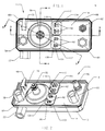
- the controller assembly indicated generally at 10 has a housing shell 12 which is covered by a cover plate 14 which is sealed by a resilient gasket or resilient seal 16 received in a cupped flange 18 formed about the periphery of the shell 12; and, the cover 14 is retained by folding over the edges of the flange 18 as shown in dashed outline in FIGS. 3, 4 and 5.
- An inlet port 20 is formed in the side wall of shell 12; and, is a suitable inlet fitting 22 attached to the exterior thereof by any suitable expedient, as for example welding or brazing and which may have internal threads 24 for connection to a fuel gas supply conduit (not shown).
- a pressure regulator body 26 is received in the interior of shell 12 and has an inlet 28 formed therein which has an annular resilient seal 31 disposed over the inlet for sealing same about the port 20 on the inner surface of the wall of shell 12.
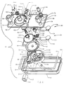
- the inlet 28 communicates with a first valving chamber 30 formed in the body 26 which has an outlet port 32 formed in the bottom thereof which communicates with a transfer passage 34 formed in the bottom of the body 26.
- the transfer passage 34 communicates with a second or regulator port 38 formed in the bottom of a record or regulator valving chamber or cavity 40 which has a plurality of outlets 42 which communicate with the interior of the shell 12.
- a pressure responsive diaphragm 44 is disposed to close the cavity 40 and form the upper wall thereof.
- the diaphragm has a peripheral bead or rim 46 sealed about the upper rim or periphery 48 of the cavity 40 by being compressed by the undersurface of the cover plate 14.
- a backing plate 50 Attached to the upper surface of the diaphragm 44 is a backing plate 50 to which is centrally attached and sealed through the diaphragm a valve operating rod 52 which extends downwardly through the regulator valve port 38 into the transfer passage 34 and has attached to the lower end thereof a resilient poppet 54.
- a preload spring 129 has one lower end registered against the backing plate 50 with its upper end registered against the cover 14.
- a conversion spring 56 has one lower end registered against the backing plate 50.
- the threaded fitting 58 as shown in FIG. 5, is covered with a protective cover 59.
- plug 58 is adjusted to provide the desired compressed length of the spring 129 provides a preload which is established sufficient to move the diaphragm downwardly to cause poppet 54 to be unseated at a desired pressure in cavity 40. Thereafter, variations in the pressure and chamber 40 will cause the diaphragm to either decrease the opening between the poppet 54 and port 38 with increasing pressure, or with decreasing pressure, allow the diaphragm to drop under the urging of spring 129.
- the maximum opening of the poppet 54 with respect to port 38 is limited by stops 62 provided in the chamber 40 against which the undersurface of the diaphragm is registered when the pressure in chamber 40 drops below a predetermined minimum.
- the manual shut off valve poppet 64 is attached to the end of an operating rod 66 which extends upwardly through an aperture in the cover 14 and has the upper end thereof pivotally connected to a lift type tab actuator 68 by a pin 70.
- the cover plate 14 has at least two and preferably three spaced outlet ports 72, 74, 76 formed therein attached to each of which is attached to an outlet fitting denoted respectively 78, 80, 82, which are secured by any suitable expedient such as welding or brazing.
- outlet fitting 78 is adapted for connection to a conduit supplying one or more top burners such as to a top burner manifold.
- Outlet 80 is preferably connected to an oven “Broil” burner; whereas, outlet 82 is adapted for connection to a conduit supplying an oven "Bake” burner.
- diaphragm rim 46 extends outwardly as denoted by reference numeral 47 and is configured to seal over the top of the body cap 30 by virtue of the pressure of the undersurface of cover plate 14.
- valve actuators 84, 86 are disposed on the undersurface of cover plate 14 for providing a valving function of the outlet ports 74, 76.
- Valve actuators 84, 86 include a mounting block respectively 88, 90 which in the present practice are formed of insulating material such as a ceramic.
- the blocks 88, 90 are attached to the cover 14 by conductive rivets such as denoted typically by reference numeral 92 which pass through correspondingly disposed apertures respectively 94, 96 and 98, 100 formed in the cover plate 14.
- the rivets extend upwardly through insulator pads respectively 102, 104 provided on the exterior of cover plate 14 and through electrical connector terminals 106, 108 and 110, 112 situated on the pads 102, 104. It will be understood that each of the rivets is riveted over one of the connector terminals 106, 108, 110, 112 for retaining the assembly of the block, pad and terminals onto the cover plate 14.
- Each of the blocks 88, 90 has attached thereto a bimetal arm respectively 114, 116 about which is wrapped a wire heating coil 118, 120 which has its ends connected respectively to one of the rivets 92 mounting the blocks to the cover plate.
- the coil 118 has its ends electrically connected respectively to the terminals 106, 108 and coil 120 has its ends connected to terminals 110, 112.
- Each of the bimetal arms 114, 116 has an extension mounted to the end thereof denoted respectively 122, 124 which extensions may also be of bimetal construction and oppositely disposed with respect to arms 114, 116 for ambient temperature compensation in a manner well known in the art.
- Each of the extensions 122, 124 has attached to the free end thereof a resilient elastomeric poppet denoted respectively by reference numerals 126, 128. It will be understood that the valve actuators 84, 86 are so disposed that poppet 126 closes against the undersurface of port 74 in the cover; and, poppet 128 closes against the undersurface of port 76 in the cover plate.
- the poppets 126, 128 are biased to a closed position against their respective outlet ports. Upon energization of either of the coils 118, 120, the corresponding poppet is moved away from the outlet port and permitting flow through one of the ports 74, 76.
- outlet port 72 in the cover plate is continuously open with respect to the interior of shell 12; and, opening of the manual shut off valve poppet 64 results in fuel gas flow through port 72.
- port 72 is adapted to be connected to a manifold for top burners each of which has its own shut off valve.
- the present invention thus provides a unique and novel combination manual shut-off valve pressure regulator and plural electrically operated valves for controlling flow to selected fuel gas burners.
- the present invention provides a simplified construction for the combination controller wherein the pressure regulator is partially formed by the cover plate; and, the outlets and valve operators are connected to the cover plate as a sub-assembly simplifying manufacturing and providing for minimal cost.
Landscapes
- Engineering & Computer Science (AREA)
- Chemical & Material Sciences (AREA)
- Combustion & Propulsion (AREA)
- Mechanical Engineering (AREA)
- General Engineering & Computer Science (AREA)
- Feeding And Controlling Fuel (AREA)
- Magnetically Actuated Valves (AREA)
- Regulation And Control Of Combustion (AREA)
Applications Claiming Priority (2)
| Application Number | Priority Date | Filing Date | Title |
|---|---|---|---|
| US72544496A | 1996-10-04 | 1996-10-04 | |
| US725444 | 1996-10-04 |
Publications (2)
| Publication Number | Publication Date |
|---|---|
| EP0834698A2 true EP0834698A2 (fr) | 1998-04-08 |
| EP0834698A3 EP0834698A3 (fr) | 1999-10-13 |
Family
ID=24914584
Family Applications (1)
| Application Number | Title | Priority Date | Filing Date |
|---|---|---|---|
| EP97116772A Withdrawn EP0834698A3 (fr) | 1996-10-04 | 1997-09-26 | Dispositif combiné à régulateur à pression et à ensemble à soupape pour commander le débit à gaz à plusieurs brûleurs |
Country Status (6)
| Country | Link |
|---|---|
| EP (1) | EP0834698A3 (fr) |
| JP (1) | JPH10110942A (fr) |
| KR (1) | KR19980032562A (fr) |
| BR (1) | BR9702941A (fr) |
| CA (1) | CA2215217A1 (fr) |
| MX (1) | MX9707580A (fr) |
Cited By (3)
| Publication number | Priority date | Publication date | Assignee | Title |
|---|---|---|---|---|
| US6722356B2 (en) * | 2002-01-22 | 2004-04-20 | Whirlpool Corporation | Gas burner valve assembly |
| US8783243B2 (en) | 2010-10-25 | 2014-07-22 | General Electric Company | Lockout system for surface burners of a cooking appliance |
| CN104633196A (zh) * | 2015-02-11 | 2015-05-20 | 河北安信燃气设备有限公司 | 超失压过流量切断保护中压进户表前调压器 |
Families Citing this family (1)
| Publication number | Priority date | Publication date | Assignee | Title |
|---|---|---|---|---|
| CN101825905B (zh) * | 2010-04-13 | 2012-02-15 | 刘永义 | 精密水位控制给水装置 |
Family Cites Families (4)
| Publication number | Priority date | Publication date | Assignee | Title |
|---|---|---|---|---|
| JPS5875617A (ja) * | 1981-10-28 | 1983-05-07 | Matsushita Electric Ind Co Ltd | ガス圧力調整装置 |
| US4424830A (en) * | 1981-12-16 | 1984-01-10 | Emerson Electric Co. | Gas valve |
| US5318268A (en) * | 1993-06-10 | 1994-06-07 | Eaton Corporation | Thermally actuated valve with ambient temperature compensation |
| DK9500110U4 (da) * | 1995-03-20 | 1996-06-20 | Bm Controls As | Gasmagnetventil |
-
1997
- 1997-09-25 CA CA002215217A patent/CA2215217A1/fr not_active Abandoned
- 1997-09-26 EP EP97116772A patent/EP0834698A3/fr not_active Withdrawn
- 1997-10-02 MX MX9707580A patent/MX9707580A/es not_active Application Discontinuation
- 1997-10-02 JP JP9269697A patent/JPH10110942A/ja active Pending
- 1997-10-03 BR BR9702941A patent/BR9702941A/pt not_active Application Discontinuation
- 1997-10-04 KR KR1019970051135A patent/KR19980032562A/ko not_active Withdrawn
Non-Patent Citations (1)
| Title |
|---|
| None |
Cited By (4)
| Publication number | Priority date | Publication date | Assignee | Title |
|---|---|---|---|---|
| US6722356B2 (en) * | 2002-01-22 | 2004-04-20 | Whirlpool Corporation | Gas burner valve assembly |
| US8783243B2 (en) | 2010-10-25 | 2014-07-22 | General Electric Company | Lockout system for surface burners of a cooking appliance |
| CN104633196A (zh) * | 2015-02-11 | 2015-05-20 | 河北安信燃气设备有限公司 | 超失压过流量切断保护中压进户表前调压器 |
| CN104633196B (zh) * | 2015-02-11 | 2017-02-01 | 河北安信燃气设备有限公司 | 超失压过流量切断保护中压进户表前调压器 |
Also Published As
| Publication number | Publication date |
|---|---|
| JPH10110942A (ja) | 1998-04-28 |
| MX9707580A (es) | 1998-04-30 |
| BR9702941A (pt) | 1998-12-01 |
| KR19980032562A (ko) | 1998-07-25 |
| EP0834698A3 (fr) | 1999-10-13 |
| CA2215217A1 (fr) | 1998-04-04 |
Similar Documents
| Publication | Publication Date | Title |
|---|---|---|
| US5937846A (en) | Fluid control assembly | |
| US6062245A (en) | Gaseous fuel burner manifold with integral pressure regulator assembly | |
| US5988204A (en) | Adjustable fluid flow regulator | |
| US5318268A (en) | Thermally actuated valve with ambient temperature compensation | |
| US4053136A (en) | Control circuit and adjustable valve for a gas appliance | |
| CA1237704A (fr) | Robinet pour le gaz | |
| EP0834698A2 (fr) | Dispositif combiné à régulateur à pression et à ensemble à soupape pour commander le débit à gaz à plusieurs brûleurs | |
| CN114165628A (zh) | 燃气烤箱智能阀及燃气烤箱 | |
| MXPA97007580A (en) | Combined set of pressure regulator and valve to control the combustible gas flow to various burned | |
| CN205298648U (zh) | 一种燃气取暖炉与灶具通用的比例阀 | |
| US4749005A (en) | Combined gas pressure regulator and shut off valve | |
| CN213929538U (zh) | 燃气阀及燃气灶 | |
| US5190452A (en) | Heat exchanger control system, control valve device therefor and methods of making the same | |
| US4303195A (en) | Thermally responsive valve device | |
| US3896857A (en) | Control device having a bleed valve and an automatic valve operated sequentially by a single bimetal element | |
| US20060249211A1 (en) | Actuator and actuator driven control device | |
| US20100243928A1 (en) | Modular gas valve arrangement | |
| US3496951A (en) | Convertible control manifold assembly | |
| CA1280726C (fr) | Clapet de commande-regulation thermostatique pour bruleur au mazout | |
| CN212297746U (zh) | 一种具有自动火力切换功能的阀体结构 | |
| US4692574A (en) | Differential pressure responsive switch | |
| US3981674A (en) | Control circuit and adjustable valve for a gas appliance | |
| CN111237502A (zh) | 一种具有自动火力切换功能的阀体结构 | |
| CN223595989U (zh) | 燃气控制装置和燃气灶 | |
| CN109373366B (zh) | 燃气灶及其控制方法 |
Legal Events
| Date | Code | Title | Description |
|---|---|---|---|
| PUAI | Public reference made under article 153(3) epc to a published international application that has entered the european phase |
Free format text: ORIGINAL CODE: 0009012 |
|
| AK | Designated contracting states |
Kind code of ref document: A2 Designated state(s): AT BE CH DE DK ES FI FR GB GR IE IT LI LU MC NL PT SE |
|
| AX | Request for extension of the european patent |
Free format text: AL;LT;LV;RO;SI |
|
| PUAL | Search report despatched |
Free format text: ORIGINAL CODE: 0009013 |
|
| AK | Designated contracting states |
Kind code of ref document: A3 Designated state(s): AT BE CH DE DK ES FI FR GB GR IE IT LI LU MC NL PT SE |
|
| AX | Request for extension of the european patent |
Free format text: AL;LT;LV;RO;SI |
|
| AKX | Designation fees paid | ||
| REG | Reference to a national code |
Ref country code: DE Ref legal event code: 8566 |
|
| STAA | Information on the status of an ep patent application or granted ep patent |
Free format text: STATUS: THE APPLICATION IS DEEMED TO BE WITHDRAWN |
|
| 18D | Application deemed to be withdrawn |
Effective date: 20000401 |