EP0834474B1 - Procédé de purification en discontinu et installation pour la mise en oeuvre de ce procédé - Google Patents
Procédé de purification en discontinu et installation pour la mise en oeuvre de ce procédé Download PDFInfo
- Publication number
- EP0834474B1 EP0834474B1 EP97113803A EP97113803A EP0834474B1 EP 0834474 B1 EP0834474 B1 EP 0834474B1 EP 97113803 A EP97113803 A EP 97113803A EP 97113803 A EP97113803 A EP 97113803A EP 0834474 B1 EP0834474 B1 EP 0834474B1
- Authority
- EP
- European Patent Office
- Prior art keywords
- buffer tank
- phase
- waste water
- cycle
- filling
- Prior art date
- Legal status (The legal status is an assumption and is not a legal conclusion. Google has not performed a legal analysis and makes no representation as to the accuracy of the status listed.)
- Expired - Lifetime
Links
Images


Classifications
-
- C—CHEMISTRY; METALLURGY
- C02—TREATMENT OF WATER, WASTE WATER, SEWAGE, OR SLUDGE
- C02F—TREATMENT OF WATER, WASTE WATER, SEWAGE, OR SLUDGE
- C02F3/00—Biological treatment of water, waste water, or sewage
- C02F3/02—Aerobic processes
- C02F3/12—Activated sludge processes
- C02F3/1236—Particular type of activated sludge installations
- C02F3/1263—Sequencing batch reactors [SBR]
-
- Y—GENERAL TAGGING OF NEW TECHNOLOGICAL DEVELOPMENTS; GENERAL TAGGING OF CROSS-SECTIONAL TECHNOLOGIES SPANNING OVER SEVERAL SECTIONS OF THE IPC; TECHNICAL SUBJECTS COVERED BY FORMER USPC CROSS-REFERENCE ART COLLECTIONS [XRACs] AND DIGESTS
- Y02—TECHNOLOGIES OR APPLICATIONS FOR MITIGATION OR ADAPTATION AGAINST CLIMATE CHANGE
- Y02W—CLIMATE CHANGE MITIGATION TECHNOLOGIES RELATED TO WASTEWATER TREATMENT OR WASTE MANAGEMENT
- Y02W10/00—Technologies for wastewater treatment
- Y02W10/10—Biological treatment of water, waste water, or sewage
Definitions
- a wastewater treatment plant is described with a raw wastewater inlet, possibly a mechanical one Cleaning stage, a multifunctional (i.e. possibly can also be used as a (pre-acidifying) primary clarifier) Buffer pool, at least one buffer pool and one biological stage consisting of at least one biological Reactor, the raw sewage feed into the Buffer pool leads and biological from the buffer pool Charged reactors batchwise (i.e. discontinuously) be provided.
- No. 5,395,527 describes a method and a device described for wastewater treatment in a wastewater treatment plant with a raw sewage inlet and a buffer stage provided with a circulation device is described, the buffer stage consisting of a with feed pumps provided buffer pool, and a reactor stage is provided with an SBR reactor.
- This system uses the procedure described not very extensive denitrification and phosphate elimination reached. Next are the operating costs by minimizing energy costs.
- the buffer tank serves as a template / mixing and expansion tank for the biological reactors (hereinafter referred to as SBR reactors).
- SBR reactors biological reactors
- There are one or more stirrers in the buffer tank which, when in operation, bring the settable components of the raw sewage or the filterable substances ( TS 0 ) into suspension.
- Pumps pump the wastewater from the buffer tank into the SBR reactors at defined times.
- Waste water is supplied at the beginning of the filling phases out of the buffer basin preferably without aeration of the or the SBR reactors.
- the revolution in the reactors is started at the same time and can alternatively in the meantime will then be preferred started again before the end of the loading phase.
- volume exchange ratio Ratio of amount of wastewater supplied during a Total cycle or an internal cycle to the volume of the SBR reactor defined at full charge.
- the denitrification capacity is at best (if the Denitrification during the filling and mixing phase (s) completely runs) directly inversely proportional to Volume exchange ratio.
- a high nitrate concentration at the end of the cycle is also very problematic because (uncontrollable, essentially dependent on the endogenous respiratory capacity) denitrification processes with the result of N 2 outgassing during the sedimentation and decanting phase can lead to a buoyancy of activated sludge flakes, which then the decanter would get into the receiving water.
- the invention has for its object a method of the type mentioned and a wastewater treatment plant of the specified structure with which a complete denitrification and one biological P-elimination as far as possible as well an avoidance of swelling and floating sludge formation and at the same time or as a direct consequence of it the operating costs mainly through minimization the energy costs for ventilation, a reduction in Wastewater tax, a minimization / total elimination of Falling agent costs for chemical P elimination as well a minimization of the excess sludge and the Investment costs through a reduction in the required SBR reactor volume can be reduced.
- the invention teaches a specific method for discontinuous wastewater treatment, in which the wastewater is conveyed from a buffer tank in SBR reactors with at least two internal cycles, during the filling phase of the first internal cycle (s) of pre-clarified wastewater (i.e. supernatant) the buffer tank (this also serves as a primary clarifier during this time) is conveyed into the SBR reactor, and in the next (possibly last) filling phase a significantly smaller amount of concentrated waste water (i.e. sediment) from the buffer tank into the SBR reactor Reactor is promoted, pre-clarified wastewater is obtained by taking wastewater from the upper area of the buffer basin while the circulation is switched off (thus it is a wastewater fraction that is largely free of sedimentable components, i.e.
- a direct measurement can be done online, for example Nitrate measurement, an indirect one over the course of the Redox potential and / or the pH value (the more nitrogen nitrification, the more the pH value will drop); an estimate can be made about the time and the amount of wastewater supplied.
- the invention is based on the knowledge that with otherwise constant general conditions, in particular constant BOD 5 / TS 0 ratio, the BOD 5 freight determines linearly proportional how much nitrogen from the raw sewage is incorporated into the excess sludge. Specifically, this means that, for example, if the BOD 5 / N total ratio is doubled by doubling the BOD 5 freight, double the amount of nitrogen is incorporated into the excess sludge and a correspondingly smaller amount is nitrified or can be nitrified.
- the invention proceeds from the knowledge that very many types of wastewater (and only related to them) the present invention), especially domestic Wastewater, with the help of sedimentation processes in two Fractions can be divided:
- pre-clarified wastewater is conveyed with a relatively low BOD 5 / N total ratio in the SBR reactor.
- a relatively high proportion of the total nitrogen is therefore nitrified.
- a further reduction in energy consumption for the Ventilation results from the fact that with the complete denitrification a correspondingly larger one Nitrate oxygen content is used for breathing, whereby a corresponding reduction in the required Proportion of oxygen from the ventilation results.
- a third advantage of the ventilation equipment results from the fact that the required denitrification volume (essentially equivalent to the filling and mixing phase of the last internal cycle) compared to conventional methods for kinetic reasons (both higher NO 3 and BOD 5 concentration on Beginning of the denitrification phase) is lower. Since the nitrification volume thus becomes relatively larger, the required ventilation equipment can be designed correspondingly smaller.
- the extent of the hydrolysis / pre-acidification becomes decisive on the average length of stay of the primary sludge in the buffer tank; by one To achieve extensive hydrolysis / pre-acidification should preferably a stay of about three days can be set. This can be set as required with the desired impact on the above described fractionation of waste water for the purpose of further Denitrification.
- the invention further proceeds from the Realizing that the effectiveness of biological Phosphorus elimination is very much determined by that during the anaerobic phase (here the filling and Mixed phase of the first internal cycle) Waste water with the lowest possible nitrate concentration is present. Exactly this ratio is used brought about the method according to the invention.
- this can be a wide one achieved higher biological phosphate elimination rate than with conventional methods. As a direct result this results in a lower need for precipitant (This may even - depending on the Raw sewage composition - completely eliminated), a less excess sludge and as a result a higher mud age, which is a reduction of the required SBR reactor volume.
- the circulation in the buffer basin is just before the start of the Filling phase of the last internal cycle started.
- This Embodiment is preferably applied if no separate stabilization of the excess sludge is intended for all of the primary sludge biological treatment in the SBR reactors can be.
- the Invention is the filling of the last internal Cycle with predominantly settled primary sludge (the Circulation in the buffer container is therefore a certain one Time before the start of this last filling phase).
- the Circulation in the buffer container is therefore a certain one Time before the start of this last filling phase.
- the remaining primary sludge (as well as the excess sludge from the SBR reactors) is expedient anaerobic stabilization, for example in one Digestion tower, fed.
- the inventive method are significant Construction cost savings possible because only the addition of primary sludge required for the required denitrification to minimize total freight (and thus the required volume) to the SBR reactors leads.
- This embodiment also opens up the possibility of very effectively treating the turbid and filtrate water from the anaerobic sludge treatment with a usually very low BOD 5 / N total ratio:
- this addition mode can be selected to prevent excessive nitrite formation). This ensures that the total N total freight of the cloudy / filtrate water can be completely nitrified as well as completely denitrified.
- the Invention is the filling of the last internal Cycle with predominantly settled primary sludge (the Circulation in the buffer tank is therefore a certain one Time before the start of this last filling phase). However, this is done, however, with several total cycles distributed as evenly as possible, the whole accruing Primary sludge fed to the SBR reactors, see above that only the secondary sludge as excess sludge from the SBR reactors.
- the invention also relates to a wastewater treatment plant for the implementation of the above Process involving a raw sewage feed, one mechanical pre-cleaning, a preliminary / mixing and compensation stage consisting of at least one buffer pool and SBR reactors, the buffer basin (s) with the SBR reactors connected and the raw sewage supply via the mechanical cleaning stage in the buffer tank leads, but within the first internal cycles only pre-treated wastewater from the buffer basin into the SRB reactors is promoted and as part of the last internal Only concentrated wastewater from the cycle Buffer basin is promoted in the SBR reactors and if necessary, an adequate measuring device the amount / type of concentrated Waste water determined in the SBR reactors is promoted, is provided.
- 1 is a sewage treatment plant according to the invention to carry out the method according to the invention shown for wastewater treatment. It deals is a plant with a buffer tank and 2 SBR reactors. The way of mechanical pretreatment and possibly the sludge treatment is related to that Claims not relevant and therefore also here not shown.
- the raw sewage inlet 1 to the buffer tank is shown, the buffer tank 2 with a circulation stirrer 3, Feed pumps 4a and 4b and an optional one actuating primary sludge extraction pump 5.
- the SBR reactors 6 and 7 are on the feed lines 8 and 9 from the buffer tank with fractionated Raw sewage is fed.
- the ventilation is 10 and 11 can be operated intermittently.
- the circulating devices 12 and 13 of the SBR reactors are at least during the Sedimentation and decanting phases stopped.
- the Excess sludge pumps 14 and 15 promote the excess sludge preferably at the end of the sedimentation phase the SBR reactors.
- About the clear water drains 16 and 17 the clear water is drained into the (optional) clear water buffer.
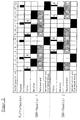
- 2 and 3 are two exemplary embodiments Overall cycle strategies along a time axis shown.
- the total cycle time is for both SBR reactors 8 h with 2 internal ones Cycles, but depending on the raw wastewater composition, Amount and cleaning goal shorter or longer be and include multiple internal cycles.
- the asynchrony is 4 hours, but it is freely selectable and essentially dependent on the Amount of wastewater, the number of SBR reactors, the type and Way of providing concentrated wastewater as well as the duration of the internal cycles and the temporal Overlap of the internal cycles of the SBR reactors.
- Asynchrony for example, must be geared towards this that there is no overlap in one Reactor and concentrated wastewater on starting the circulation device in the buffer tank in the other Reactor can be funded.
- the provision is made the concentrated wastewater fraction Starting the circulation device 3 in the buffer tank 2 shortly before filling the last internal cycle.
- the feed pumps 4a or 4b then promote the Primary sludge highly enriched wastewater fraction B in an SBR reactor.
- complete denitrification under anoxic conditions C At the end of this phase, you may be under partial anaerobic conditions a certain P-redissolution takes place, however, this process is controlled irrelevant to the invention.
- the ventilation phase takes about 2 hours the respiration of Remaining BOD and the inclusion of the remaining solved Phosphates and the nitrification of the relatively low Nitrogen share.
- the feed pumps can be equipped with a plurality of Lines connected to buffer tank 2 at different heights either supernatant or sediment to promote, depending on which of the lines with closed or opened with a corresponding slide is.
- Deviating from this embodiment are according to the invention more than two internal cycles possible; in the As part of the biological P elimination via the feed with supernatant, however, is only an internal one Cycle makes sense while in the context of denitrification quite a few about loading with desimentat successive internal cycles helpful / useful can be, especially if only a moderate fractionation is possible and a very extensive denitrification is required.
- Fig. 3 the provision the concentrated wastewater fraction B, that from the area of the bottom of the pelvis basin is filled while the circulation is switched off is.
- This wastewater fraction therefore essentially exists from sedimented primary sludge.
- the feed pump 4a conveys the primary sludge in an SBR reactor.
- the residual BOD is breathed under oxic conditions D as well as the biological absorption of the phosphate supplied with the raw sewage and the one released in the previous anaerobic phase and the complete nitrification of the relatively high nitrogen content.
- a filling process is carried out with a highly enriched wastewater fraction B (see above).
- the primary sludge removal column is in FIG. 3 has been added to indicate that preferably a separate one in this embodiment Excess sludge stabilization takes place. However, this is also possible according to embodiment 1.
- a total cycle time of 4 hours is selected with only one internal cycle (the result is identical to a total cycle time of 8 hours and two internal cycles of the same length) and thus a maximum volume exchange rate of 18%.
- a nitrate N concentration of approx. 8.6 mg / l results at the end of the cycle.
Landscapes
- Life Sciences & Earth Sciences (AREA)
- Biodiversity & Conservation Biology (AREA)
- Microbiology (AREA)
- Hydrology & Water Resources (AREA)
- Engineering & Computer Science (AREA)
- Environmental & Geological Engineering (AREA)
- Water Supply & Treatment (AREA)
- Chemical & Material Sciences (AREA)
- Organic Chemistry (AREA)
- Purification Treatments By Anaerobic Or Anaerobic And Aerobic Bacteria Or Animals (AREA)
- Activated Sludge Processes (AREA)
Claims (8)
- Procédé pour l'épuration discontinue d'eaux usées avec des stratégies de cycles internes différenciées, caractérisé en ce queles eaux usées sont conduites d'un bassin tampon (2) servant au fractionnement des eaux usées brutes, équipé d'un dispositif de circulation, dans au moins un réacteur SBR (6 ou 7)à au moins deux cycles internes,pendant la phase de remplissage du ou des premiers cycles internes, des eaux usées pré-décantées, formant un surnageant peu chargé, sont conduites du bassin tampon (2) dans le réacteur SBR (6 ou 7),au moins pendant la dernière phase de remplissage du cycle complet, une quantité essentiellement faible d'eaux usées concentrées est conduite, essentiellement en tant que sédiment, du bassin tampon (2) dans le réacteur SBR (6 ou 7),la circulation étant à l'arrêt, des eaux usées, pré-décantées, son prélevées à partir de la zone supérieure du bassin tampon (2),la circulation étant active, des eaux usées concentrées sont prélevées du bassin tampon (2), grâce à quoi une grande quantité de sédiments est entraínée simultanément, ou des eaux usées concentrées sont extraites en prélevant des eaux usées de la zone du fond du bassin tampon (2), et des sédiments sont ainsi convoyés pratiquement exclusivement (le cas échéant, en même temps qu'une certaine quantité de surnageant), etla quantité de nitrate à dénitrifier est déterminée directement ou indirectement, après le premier resp. l'avant-dernier cycle et, sur cette base, la quantité / le type d'eaux usées concentrées est déterminé pour le dernier cycle interne.
- Procédé selon la revendication 1, caractérisé en ce que la phase de remplissage et aussi, le cas échéant, la phase de circulation pure du premier cycle interne y faisant suite, servent essentiellement à l'élimination biologique de P et une commande / régulation de la durée nécessaire de cette phase est effectuée par l'intermédiaire d'un dispositif de mesure adéquat.
- Procédé selon les revendications 1 et 2, caractérisé en ce que 1 à 2 heures environ avant l'opération de remplissage avec du surnageant, la circulation (3) dans le bassin tampon (2) est brièvement mise en marche afin d'enlever par lavage les éléments de DBO5 facilement dégradables.
- Procédé selon la revendication 1, caractérisé en ce que la phase de remplissage et aussi, le cas échéant, la phase de circulation pure du / des derniers cycles internes est utilisée pour la dénitrification et une commande / régulation de la durée nécessaire de cette phase est effectuée par l'intermédiaire de dispositifs de mesure adéquats.
- Procédé selon les revendications 1 et 4, caractérisé en ce que la totalité de la boue primaire (le cas échéant accumulée au cours du temps), produite dans le bassin tampon (2) est conduite, pour stabilisation simultanée de la boue, dans le / les réacteurs SBR.
- Procédé selon les revendications 1 et 4, caractérisé en ce que seule la partie de boue primaire nécessaire à la dénitrification, accumulée au cours du temps dans le / les réacteurs SBR, est transportée, ce par quoi une stabilisation séparée des boues est effectuée.
- Procédé selon la revendication 1, caractérisé en ce que, pendant la phase de remplissage et / ou la phase d'aération du/ des premiers (mais pas du dernier) cycles internes, de l'eau boueuse / de l'eau de filtration est conduite dans le / les réacteurs SBR.
- Installation d'épuration d'eaux usées pour l'exécution d'un procédé présentant les caractéristiques des revendications 1 à 7, avecla / les pompes d'alimentation (4a ; 4b) pouvant être raccordées, à différentes hauteurs, au bassin tampon (2).une amenée d'eaux usées brutes (1),un étage tampon (2) pourvu d'un système de circulation, composé d'au moins un bassin tampon pourvu de pompes d'alimentation,un étage réacteur (6 et 7) avec au moins un réacteur SBR,
Applications Claiming Priority (2)
| Application Number | Priority Date | Filing Date | Title |
|---|---|---|---|
| DE19640762 | 1996-10-02 | ||
| DE19640762A DE19640762C1 (de) | 1996-10-02 | 1996-10-02 | Verfahren zur diskontinuierlichen Abwasserreinigung und Anlage zur Durchführung dieses Verfahrens |
Publications (3)
| Publication Number | Publication Date |
|---|---|
| EP0834474A2 EP0834474A2 (fr) | 1998-04-08 |
| EP0834474A3 EP0834474A3 (fr) | 2001-06-13 |
| EP0834474B1 true EP0834474B1 (fr) | 2003-07-23 |
Family
ID=7807745
Family Applications (1)
| Application Number | Title | Priority Date | Filing Date |
|---|---|---|---|
| EP97113803A Expired - Lifetime EP0834474B1 (fr) | 1996-10-02 | 1997-08-09 | Procédé de purification en discontinu et installation pour la mise en oeuvre de ce procédé |
Country Status (3)
| Country | Link |
|---|---|
| EP (1) | EP0834474B1 (fr) |
| DE (2) | DE19640762C1 (fr) |
| ES (1) | ES2198521T3 (fr) |
Cited By (2)
| Publication number | Priority date | Publication date | Assignee | Title |
|---|---|---|---|---|
| DE102005048146A1 (de) * | 2005-10-07 | 2007-04-12 | Holm, Niels Christian, Dr. | Verfahren zur diskontinuierlichen Abwasserreinigung |
| CZ301099B6 (cs) * | 2005-12-15 | 2009-11-04 | Medmes, Spol. S R. O. | Zpusob biologického cištení odpadních a deštových vod s prerušovaným provozem a zarízení k provádení tohoto zpusobu |
Families Citing this family (8)
| Publication number | Priority date | Publication date | Assignee | Title |
|---|---|---|---|---|
| DE19802957C1 (de) * | 1998-01-27 | 1999-03-04 | Koester Bau Ag & Co | Verfahren zur diskontinuierlichen Abwasserreinigung |
| DE102005007408A1 (de) | 2005-02-18 | 2006-08-24 | Holm, Niels Christian, Dr. | Verfahren zur Verbesserung der Denitrifikation und Bio-P-Elimination beim SBR-Verfahren |
| EP1903010A1 (fr) * | 2006-09-22 | 2008-03-26 | Holm, Niels Christian | Procédé de traitement d'eaux usées dans des installations à boue activée alimentées en continu comprenant une dénitrification en amont |
| DE102009037433B4 (de) | 2009-08-13 | 2017-03-30 | Niels Christian Holm | Verfahren und Vorklärbecken zur Optimierung der Vorklärung von Kläranlagen |
| EP2289855B1 (fr) * | 2009-08-31 | 2014-10-15 | Peter Hartwig | Installation de nettoyage d'eaux usées et procédé de nettoyage d'eaux usées |
| DE102009039316A1 (de) * | 2009-08-31 | 2011-03-31 | Hartwig, Peter, Dr.-Ing. | Abwasserreinigungsanlage und Verfahren zur Abwasserreinigung |
| DE202013010447U1 (de) * | 2013-11-21 | 2015-02-24 | Zwt Wasser- Und Abwassertechnik Gmbh | Vorrichtung zur Behandlung von Aowasser vom Regulierungseinheit einer Vorrichtung zur Behandlung von Abwasser |
| AT526134B1 (de) * | 2022-05-02 | 2024-03-15 | Gassner Ing Kurt | Diskontinuierliches abwasserreinigungsverfahren |
Family Cites Families (4)
| Publication number | Priority date | Publication date | Assignee | Title |
|---|---|---|---|---|
| US5192442A (en) * | 1991-12-02 | 1993-03-09 | Zimpro Passavant Environmental Systems, Inc. | Multiple zone batch treatment process |
| US5395527A (en) * | 1993-07-01 | 1995-03-07 | Eco Equipement Fep Inc. | Process and apparatus for treating wastewater in a dynamic, bio sequenced manner |
| DE4332815A1 (de) * | 1993-09-27 | 1995-04-13 | Uta Ges Fuer Umwelttechnik Und | Kläranlage nach dem SBR-Prinzip |
| DE19519742C2 (de) * | 1994-06-06 | 1996-12-12 | Holm Niels Christian Dr | Verfahren zur Abwasserreinigung mit intermittierender Nitrifikation/Dentrifikation und Abwasserreinigungsanlage zur Durchführung des Verfahrens |
-
1996
- 1996-10-02 DE DE19640762A patent/DE19640762C1/de not_active Expired - Lifetime
-
1997
- 1997-08-09 ES ES97113803T patent/ES2198521T3/es not_active Expired - Lifetime
- 1997-08-09 EP EP97113803A patent/EP0834474B1/fr not_active Expired - Lifetime
- 1997-08-09 DE DE59710463T patent/DE59710463D1/de not_active Expired - Lifetime
Cited By (2)
| Publication number | Priority date | Publication date | Assignee | Title |
|---|---|---|---|---|
| DE102005048146A1 (de) * | 2005-10-07 | 2007-04-12 | Holm, Niels Christian, Dr. | Verfahren zur diskontinuierlichen Abwasserreinigung |
| CZ301099B6 (cs) * | 2005-12-15 | 2009-11-04 | Medmes, Spol. S R. O. | Zpusob biologického cištení odpadních a deštových vod s prerušovaným provozem a zarízení k provádení tohoto zpusobu |
Also Published As
| Publication number | Publication date |
|---|---|
| DE19640762C1 (de) | 1997-12-18 |
| EP0834474A2 (fr) | 1998-04-08 |
| EP0834474A3 (fr) | 2001-06-13 |
| DE59710463D1 (de) | 2003-08-28 |
| ES2198521T3 (es) | 2004-02-01 |
Similar Documents
| Publication | Publication Date | Title |
|---|---|---|
| DE3501585C2 (fr) | ||
| EP0284976B1 (fr) | Procédé pour la purification d'eau usée avec une alimentation de bassin à boues activées | |
| EP0834474B1 (fr) | Procédé de purification en discontinu et installation pour la mise en oeuvre de ce procédé | |
| EP0497114A1 (fr) | Procédé d'épuration d'eaux résiduaires contenant des phosphates et des composés azotés | |
| DE2233801B2 (de) | Verfahren zur biologischen Reinigung von Abwasser mit zwei von dem Abwasser nacheinander durchflossenen Stufen | |
| EP0273111B1 (fr) | Procédé et installation pour la purification des eaux résiduaires contenant des phosphates et pour l'élimination du phosphore par voie biologique | |
| EP1531123B1 (fr) | Méthode et installation pour traiter des eaux de déchet de bateaux | |
| DE3833185C2 (fr) | ||
| DE69729249T2 (de) | Abwasserreinigungsverfahren | |
| WO1991017959A1 (fr) | Procede d'elimination de nitrates et de phosphates lors de l'epuration biologique d'eaux d'egouts | |
| DE3907734C1 (fr) | ||
| AT395845B (de) | Verfahren zur reinigung von organische substanzen enthaltenden abwaessern | |
| DE19802957C1 (de) | Verfahren zur diskontinuierlichen Abwasserreinigung | |
| DE3507388A1 (de) | Verfahren fuer die reinigung von abwasser | |
| AT396684B (de) | Belebtschlammverfahren zur reinigung von abwasser | |
| DE2924449C2 (de) | Verfahren zum Reinigen von Abwasser nach dem Belebtschlammverfahren | |
| DE19640761C1 (de) | Verfahren zur kontinuierlichen Abwasserreinigung und Anlage zur Durchführung dieses Verfahrens | |
| EP0087129A1 (fr) | Procédé et dispositif pour la nitrification biologique des eaux usées | |
| DE102015002850A1 (de) | Abfolge von Verfahren zur Behandlung von Abwasser | |
| EP1099668A1 (fr) | Procédé d'épuration de l'eau communale ou similaire usée | |
| EP0899241B1 (fr) | Procédé et dispositif pour élimination biologique de phosphore | |
| EP0802166B1 (fr) | Procédé de traitement et purification des eaux usées industrielles | |
| DE4204590C2 (de) | Verfahren zur biologischen Abwasserreinigung in einem Belebungsbecken | |
| DE19519742A1 (de) | Verfahren zur Abwasserreinigung mit intermittierender Nitrifikation/Dentrifikation und Abwasserreinigungsanlage zur Durchführung des Verfahrens | |
| DE3146622C2 (de) | Anlage für die Reinigung von Abwasser |
Legal Events
| Date | Code | Title | Description |
|---|---|---|---|
| PUAI | Public reference made under article 153(3) epc to a published international application that has entered the european phase |
Free format text: ORIGINAL CODE: 0009012 |
|
| AK | Designated contracting states |
Kind code of ref document: A2 Designated state(s): BE DE ES FR GB |
|
| AX | Request for extension of the european patent |
Free format text: AL;LT;LV;RO;SI |
|
| RAP1 | Party data changed (applicant data changed or rights of an application transferred) |
Owner name: HOLM, NIELS, DR. |
|
| RIN1 | Information on inventor provided before grant (corrected) |
Inventor name: HOLM, NIELS, DR. |
|
| PUAL | Search report despatched |
Free format text: ORIGINAL CODE: 0009013 |
|
| AK | Designated contracting states |
Kind code of ref document: A3 Designated state(s): AT BE CH DE DK ES FI FR GB GR IE IT LI LU MC NL PT SE |
|
| AX | Request for extension of the european patent |
Free format text: AL;LT;LV;RO;SI |
|
| 17P | Request for examination filed |
Effective date: 20010602 |
|
| 17Q | First examination report despatched |
Effective date: 20010718 |
|
| AKX | Designation fees paid |
Free format text: BE DE ES FR GB |
|
| GRAH | Despatch of communication of intention to grant a patent |
Free format text: ORIGINAL CODE: EPIDOS IGRA |
|
| GRAH | Despatch of communication of intention to grant a patent |
Free format text: ORIGINAL CODE: EPIDOS IGRA |
|
| GRAA | (expected) grant |
Free format text: ORIGINAL CODE: 0009210 |
|
| AK | Designated contracting states |
Designated state(s): BE DE ES FR GB |
|
| PG25 | Lapsed in a contracting state [announced via postgrant information from national office to epo] |
Ref country code: FR Free format text: LAPSE BECAUSE OF FAILURE TO SUBMIT A TRANSLATION OF THE DESCRIPTION OR TO PAY THE FEE WITHIN THE PRESCRIBED TIME-LIMIT Effective date: 20030723 |
|
| REG | Reference to a national code |
Ref country code: GB Ref legal event code: FG4D Free format text: NOT ENGLISH |
|
| GBT | Gb: translation of ep patent filed (gb section 77(6)(a)/1977) |
Effective date: 20030723 |
|
| REF | Corresponds to: |
Ref document number: 59710463 Country of ref document: DE Date of ref document: 20030828 Kind code of ref document: P |
|
| REG | Reference to a national code |
Ref country code: ES Ref legal event code: FG2A Ref document number: 2198521 Country of ref document: ES Kind code of ref document: T3 |
|
| PLBE | No opposition filed within time limit |
Free format text: ORIGINAL CODE: 0009261 |
|
| STAA | Information on the status of an ep patent application or granted ep patent |
Free format text: STATUS: NO OPPOSITION FILED WITHIN TIME LIMIT |
|
| 26N | No opposition filed |
Effective date: 20040426 |
|
| EN | Fr: translation not filed | ||
| PGFP | Annual fee paid to national office [announced via postgrant information from national office to epo] |
Ref country code: ES Payment date: 20080828 Year of fee payment: 12 |
|
| PGFP | Annual fee paid to national office [announced via postgrant information from national office to epo] |
Ref country code: GB Payment date: 20080821 Year of fee payment: 12 |
|
| GBPC | Gb: european patent ceased through non-payment of renewal fee |
Effective date: 20090809 |
|
| REG | Reference to a national code |
Ref country code: ES Ref legal event code: FD2A Effective date: 20090810 |
|
| PG25 | Lapsed in a contracting state [announced via postgrant information from national office to epo] |
Ref country code: GB Free format text: LAPSE BECAUSE OF NON-PAYMENT OF DUE FEES Effective date: 20090809 |
|
| PGFP | Annual fee paid to national office [announced via postgrant information from national office to epo] |
Ref country code: BE Payment date: 20100810 Year of fee payment: 14 |
|
| PG25 | Lapsed in a contracting state [announced via postgrant information from national office to epo] |
Ref country code: ES Free format text: LAPSE BECAUSE OF NON-PAYMENT OF DUE FEES Effective date: 20090810 |
|
| BERE | Be: lapsed |
Owner name: *HOLM NIELS Effective date: 20110831 |
|
| PG25 | Lapsed in a contracting state [announced via postgrant information from national office to epo] |
Ref country code: BE Free format text: LAPSE BECAUSE OF NON-PAYMENT OF DUE FEES Effective date: 20110831 |
|
| PGFP | Annual fee paid to national office [announced via postgrant information from national office to epo] |
Ref country code: DE Payment date: 20150721 Year of fee payment: 19 |
|
| REG | Reference to a national code |
Ref country code: DE Ref legal event code: R082 Ref document number: 59710463 Country of ref document: DE Representative=s name: BOEHMERT & BOEHMERT ANWALTSPARTNERSCHAFT MBB -, DE Ref country code: DE Ref legal event code: R081 Ref document number: 59710463 Country of ref document: DE Owner name: HOLM, NIELS CHRISTIAN, DR., DE Free format text: FORMER OWNER: HOLM, NILS, DR., 32425 MINDEN, DE |
|
| REG | Reference to a national code |
Ref country code: DE Ref legal event code: R119 Ref document number: 59710463 Country of ref document: DE |
|
| PG25 | Lapsed in a contracting state [announced via postgrant information from national office to epo] |
Ref country code: DE Free format text: LAPSE BECAUSE OF NON-PAYMENT OF DUE FEES Effective date: 20170301 |