EP0833714B1 - Machine a impacts - Google Patents
Machine a impacts Download PDFInfo
- Publication number
- EP0833714B1 EP0833714B1 EP95926552A EP95926552A EP0833714B1 EP 0833714 B1 EP0833714 B1 EP 0833714B1 EP 95926552 A EP95926552 A EP 95926552A EP 95926552 A EP95926552 A EP 95926552A EP 0833714 B1 EP0833714 B1 EP 0833714B1
- Authority
- EP
- European Patent Office
- Prior art keywords
- ram
- percussion machine
- percussion
- impact
- pressure
- Prior art date
- Legal status (The legal status is an assumption and is not a legal conclusion. Google has not performed a legal analysis and makes no representation as to the accuracy of the status listed.)
- Expired - Lifetime
Links
Images


Classifications
-
- B—PERFORMING OPERATIONS; TRANSPORTING
- B22—CASTING; POWDER METALLURGY
- B22F—WORKING METALLIC POWDER; MANUFACTURE OF ARTICLES FROM METALLIC POWDER; MAKING METALLIC POWDER; APPARATUS OR DEVICES SPECIALLY ADAPTED FOR METALLIC POWDER
- B22F3/00—Manufacture of workpieces or articles from metallic powder characterised by the manner of compacting or sintering; Apparatus specially adapted therefor ; Presses and furnaces
- B22F3/17—Manufacture of workpieces or articles from metallic powder characterised by the manner of compacting or sintering; Apparatus specially adapted therefor ; Presses and furnaces by forging
-
- B—PERFORMING OPERATIONS; TRANSPORTING
- B22—CASTING; POWDER METALLURGY
- B22F—WORKING METALLIC POWDER; MANUFACTURE OF ARTICLES FROM METALLIC POWDER; MAKING METALLIC POWDER; APPARATUS OR DEVICES SPECIALLY ADAPTED FOR METALLIC POWDER
- B22F3/00—Manufacture of workpieces or articles from metallic powder characterised by the manner of compacting or sintering; Apparatus specially adapted therefor ; Presses and furnaces
- B22F3/02—Compacting only
- B22F3/087—Compacting only using high energy impulses, e.g. magnetic field impulses
-
- B—PERFORMING OPERATIONS; TRANSPORTING
- B23—MACHINE TOOLS; METAL-WORKING NOT OTHERWISE PROVIDED FOR
- B23D—PLANING; SLOTTING; SHEARING; BROACHING; SAWING; FILING; SCRAPING; LIKE OPERATIONS FOR WORKING METAL BY REMOVING MATERIAL, NOT OTHERWISE PROVIDED FOR
- B23D15/00—Shearing machines or shearing devices cutting by blades which move parallel to themselves
- B23D15/12—Shearing machines or shearing devices cutting by blades which move parallel to themselves characterised by drives or gearings therefor
- B23D15/14—Shearing machines or shearing devices cutting by blades which move parallel to themselves characterised by drives or gearings therefor actuated by fluid or gas pressure
Definitions
- the present invention relates to percussion machines, according to the preamble of claim 1 and as known, e.g., from GB-A-546.875.
- Such machines are known and feature a striking body that uses kinetic energy to strike an object.
- a striking body may, in known manner, be driven by a spring system or by means of compressed air.
- the supply of kinetic energy upon a stroke may be so great that the object is subjected to adiabatic coalescence which entails extremely efficient machining of the material subjected to striking.
- the machining occurs without loss of material and substantially avoids the occurrence of burrs, cracks or changes in the material.
- the kinetic energy transmitted should have a value of between 100 and 200 Nm/ cm 2 cutting area.
- the striking body should have a velocity of between 3 and 10 m/s upon impact.
- a percussion machine for cutting metal rods is particularly advantageous and in that case a hollow tool is used which is movable in relation to a supply hole.
- a percussion machine utilizing compressed air allows some 200 units/minute to be cut.
- a spring-actuated percussion machine is used, some 400 units can be cut per minute.
- a housing comprising a striking body which is moved hydraulically between two end positions. Purely hydraulically the striking body can be given such movement that, upon impact with the material encountered, it emits sufficient energy at sufficient speed for adiabatic coalescence to be achieved.
- the triggering stroke should be carried out quickly and a suitable time for the process is between 5 and 15 milliseconds. This short time is made possible thanks to the feasibility of removing the pressure fluid countering the stroke extremely quickly. Thanks to this rapid removal of the counter-pressing fluid, the percussion machine according to the present invention can achieve 3000 strokes/minute.
- the striking body has two annular circumferential surfaces perpendicular to the axis of the body.
- the surface which, by means of liquid pressure, is to hold the striking body in its starting position is larger than the surface which, with the help of hydraulic pressure, is to effect a stroke movement
- the pressure fluid is suitably supplied via a hydro-pneumatic accumulator.
- two equivalent valve systems are used, constituting a valve housing comprising a cylindrical through-hole for two sealing cylinders arranged one after the other and joined by a connecting rod.
- Three annular recesses are also arranged one after the other, spaced from each other, the two outer annular recesses cooperating each with its own valve cylinder. All three annular grooves are connected, each by its own pipe, to a pressure fluid source.
- the unit with the two pressure cylinders can assume two outermost positions. In one position one of the outer annular grooves is open position to the valve body, while the other annular groove is in closed state.
- One valve system is used to control the supply of pressure fluid to the impact ram, in which case its cylinders are influenced by the pressure fluid coming from the other valve system, in which it is the two outer peripheral grooves that provide the latter cylinders with pressure fluid for their displacement.
- the rams in the other pressure system are influenced by two electromagnets operating alternately.
- the electromagnets are influenced by a switch and through the function of the switch the impact rams can be caused to perform a number of strokes per time unit. The strokes may occur continually or various intervals may be inserted between strokes, thereby offering wide variation with regard to the strokes.
- the percussion machine has also proved suitable for shaping components such as spheres.
- a tool divided into two parts is used for this purpose, the parts forming a spherical space when put together, and having a connecting tube for the supply of material such as a metal powder which has preferably been gas-atomized, and for controlling a punch to which strokes can be transmitted from the percussion machine.
- the striking body may be hollow and contain a second striking body, movable between the ends of the cavity.
- the inner striking body is influenced by means of a pressure fluid in the same manner as the surrounding impact ram. Since the impact ram consists of two units, movable in relation to each other, the nature of the stroke can be varied within wide limits. According to an advantageous embodiment the inner striking body performs a follow-up stroke in relation to the outer striking body.
- the striking body cooperates either directly or indirectly with a damping ram, said ram most preferably cooperating with an oil layer that achieves the damping effect.
- Said damping ram may suitably be caused to cooperate with a unit for regulating the stroke length of the tool. According to the invention this is achieved by the damping ram being brought to different positions, corresponding to the desired cutting length.
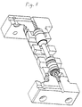
- FIG. 1 is a housing containing an impact ram 2 movable between two end positions with the aid of a surrounding band 4 with two horizontal surfaces 5 and 6 designed to be influenced by a pressure fluid.
- 7 is an inlet for pressure fluid and 8 is both inlet and outlet for pressure fluid.
- Above the impact ram is a means 9 for regulating the stroke length with the aid of a vertically movable, threaded rod 10. The rod is locked in position by means of an adjustable nut 11.
- Said stroke-length regulator 9 may be so designed that the manual adjustment may be replaced with suitable automatic means.
- Below the impact ram 2 is a two-piece tool 12, 13 for rods. 12 is a fixed cuffing tool, provided with a hole for rods.
- the cutting tool 13 is provided with a plug 15 which may be completely separate from the tool and is intended to transmit strokes from the impact ram to the movable tool 13.
- To the right of the tool 13 is a unit for carrying away cut metal units.
- the percussion machine is supplied with pressure fluid from a pump through a pipe 16. Said pressure fluid is supplied to the housing 1 via the passage 7. The oil from the pipe 16 also communicates via the pipe 18 with a hydro-pneumatic accumulator 17. The upper contact surface 5 is thus constantly under pressure.
- the connection 8, communicating with the lower contact surface 6 for the pressure fluid, is connected to a first valve system consisting of a valve housing 19 with a left-hand end portion 20 and right-hand end portion 21.
- the valve housing 19 has a cylindrical through-hole 22 containing two valve bodies 25 and 26 arranged movable between two end positions. Both the valve bodies 25 and 26 are joined to a connection piece 27 so that the two valve bodies form a single unit.
- Said unit has two conically formed units 30 and 31 designed to cooperate with recesses 32 and 33.
- the cylindrical cavity 22 has three peripheral grooves 23a, 23b and 24.
- the recesses 23a and 24 have a width slightly less than the length of the valve bodies 25 and 26 with which they shall cooperate. Grooves and valve bodies shall form two valves.
- the space where the lower contact surface 6 is located can be connected by the connection 8 either to the groove 23a which is an outlet connection, or to the peripheral groove 24 which is under liquid pressure.
- the peripheral groove 23a is connected by a pipe 63 to a pressure fluid container 64 and also to a hydro-pneumatic accumulator 65.
- the unit with the valve bodies 25 and 26 can be moved from right to left and vice versa, and the units 30 and 31 are intended as damping means, their entry into the recesses 32 and 33 filled with pressure fluid thus having a damping effect.
- the units 30 and 31 are provided with rods 28 and 29 acting as rams. These are supplied with pressure fluid via the connections 35 and 36, which moves the unit with the rams 25 and 26 to either the right or the left.
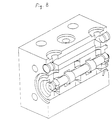
- Figure 5 shows a perspective view of how the system is constructed in practice.
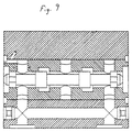
- Figures 6 and 7 show the two operating positions the system can assume.
- Pressure fluid for the last-mentioned movement is obtained from a second valve system consisting of a central part 40, a left-hand part 38 with a first electromagnet 50 and a right-hand part 39 with a second electromagnetic 52, two peripheral grooves 42 and 43 and an intermediate peripheral groove 44.
- the peripheral grooves 42 and 43 are connected to the connections 35 and 36.
- the valve system also comprises two valve bodies 45 and 46 connected by an intermediate portion 47.
- the valve bodies 45 and 46 are provided at each end with protruding rods 48 and 49. These rods constitute contact members for movable rods 51 and 53 included in the two electromagnets 50 and 52. Voltage is supplied to the two electromagnets via wires 57, 58 and 59, 60 from a voltage source 62.
- FIG. 8 shows a practical embodiment of the second valve system in perspective and Figure 9 shows said valve system in section in a working position.
- the valves 45, 46, 47, 48 and 49 can move either to the right or the left.
- the electromagnets 50 and 52 are so chosen that they have an extremely short reaction time, lying between 2 and 3 milliseconds per stroke movement.
- the unit should also be made of light material such as a light metal and may be aluminium. This enables the pressure fluid supplied to the connections 35 and 36 to perform extremely rapid movements of the valve units 25, 26 and 27, so that the unit quickly opens the valve and the opening to the pressure-fluid container 64. The pressure fluid acting upwardly on the impact ram then quickly leaves the pressure surface 6 of the impact ram. This speed is also obtained since the fluid tapped off is able to escape quickly into a space formed in the peripheral groove 23a.
- the ram unit 25, 26 and 27 will assume its left-hand position.
- the ram unit is moved to the right, whereupon the lower contact surface is again placed under pressure.
- the impact ram 2 is returned to its upper position in approximately 15 milliseconds.
- a stroke frequency of about 3000 strokes/minute can be achieved with the present percussion machine, by allowing the switch 61 to continually change position.
- the switch can also be arranged so that a number of consecutive strokes is followed by an interval, and then another number of strokes and so on. The switch thus offers infinite possibilities for varying the stroke sequences.
- the desired kinetic energy is dependent on the oil pressure on the area of the upper contact surface 5, the weight of the striking body and of its stroke length. The energy required is determined by the material to be cut.
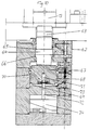
- Figure 10 shows a damping unit 62 with which the impact ram 2 can cooperate.
- the unit is provided with a ram 63 for returning the tool 13 which is provided with a surrounding band 64 having an upper contact surface for pressure fluid 65 and a lower contact surface 66 for pressure fluid.
- the transfer ram 63 cooperates with a damping ram 67 having a surrounding band 68 with an upper contact surface 70 for a pressure fluid and a lower contact surface 69 for a pressure fluid.
- the damping ram 67 has a central aperture 71 leading from its lower end surface.
- a ram 72 is arranged in this aperture in a predetermined, adjustable position.
- the rod is attached by its lower end to an adjustable unit 74, vertically movable to a desired position.
- the unit 74 may be adjusted either manually or automatically.
- the position of the unit 74 determines the cutting length of the tool 13.
- a disc 73 with a hole in it, the diameter of which allows passage of the ram 72, is secured in the lower end of the central aperture 71.
- the thickness of the disc is greater than the width of a peripheral groove of the ram 72, said peripheral groove having an outlet opening for pressure liquid that runs in the centre of the ram 72.
- the position of the damping ram 67 is fixed by the position of the peripheral groove of the ram 72. Furthermore, the actual damping effect of the damping unit is achieved by means of the oil layer appearing below the damping ram 67.
Landscapes
- Engineering & Computer Science (AREA)
- Mechanical Engineering (AREA)
- Manufacturing & Machinery (AREA)
- Percussive Tools And Related Accessories (AREA)
- Crushing And Pulverization Processes (AREA)
- Developing Agents For Electrophotography (AREA)
- Physical Or Chemical Processes And Apparatus (AREA)
- Portable Nailing Machines And Staplers (AREA)
- Punching Or Piercing (AREA)
- Valve Device For Special Equipments (AREA)
Claims (18)
- Une machine de percussion avec une unité de frappe équipée d'un outil qui, lorsqu'il fonctionne, émet une énergie cinétique d'une ampleur telle que du matériau métallique puisse être usiné avec un minimum d'altérations dans le matériau et sans perte de matériau, de préférence produisant une coalescence adiabatique,
caractérisé en ce que l'unité de frappe a un piston d'impact mobile entre deux positions d'extrémité avec deux surfaces circonférentielles (5 et 6) perpendiculaires à l'axe du piston d'impact (2), lesdites surfaces (5 et 6) pouvant être agit dessus par une pression de liquide et étant de tailles différentes, l'une des surfaces (5) exécutant la course de travail et étant plus petite que l'autre (6) qui exécute la course de retour, la pression sur la petite surface circonférentielle étant exercée en permanence, et l'espace où la pression qui agit sur la grande surface circonférentielle (6) est établie, étant doté d'un insert de sortie (8) régulé par un premier système de vannes ayant des éléments de corps (25 et 26) étant déplaçables par un fluide de pression et contrôlant la décharge et l'alimentation du fluide de pression vers ledit espace, de préférence produisant ainsi une coalescence adiabatique. - Une machine de percussion selon la revendication 1,
caractérisé en ce que la distance entre les deux positions d'extrémité est réglable. - Une machine de percussion selon la revendication 1,
caractérisé en ce que l'énergie cinétique émise lors d'une course dépend de la pression de liquide exercée sur les petites surfaces circonférentielles (5), la masse du piston d'impact (2) et la longueur de course et ayant une valeur réglée pour un usinage prédéterminé. - Une machine de percussion selon la revendication 1,
caractérisé en ce que la pression de liquide est alimentée à la petite surface circonférentielle (5) via un accumulateur hydropneumatique (17). - Une machine de percussion selon la revendication 4,
caractérisé en ce que lorsque ouverte, l'unité (25) communique avec un canal de sortie (23a). - Une machine de percussion selon la revendication 1,
caractérisé en ce que le piston d'impact (2) est creux et contient un second piston d'impact pouvant être influencé par un fluide de pression, de préférence de la même manière que le piston qui l'entoure, le second piston influençant la fonction de frappe du piston creux au moyen, par exemple, d'une course supplémentaire. - Une machine de percussion selon la revendication 1,
caractérisé en ce qu'un logement de vanne (19) comprenant un alésage cylindrique traversant (22) et deux corps de vanne (25 et 26) agencés l'un après l'autre dans l'alésage (22) et assemblés par une tige de connexion (27), trois évidements annulaires agencés l'un après l'autre, espacés l'un de l'autre et perpendiculaires à l'alésage (22), lesdits évidements (23a, 23b et 24) ayant de préférence une section quadrique et communiquant avec le fluide de pression, les deux rainures extérieures (23a et 24) étant conçues pour former des vannes avec les deux corps de vannes (25 et 26). - Une machine de percussion selon la revendication 7,
caractérisé en ce que la longueur d'au moins un piston d'étanchéité (25) est considérablement plus grande que la largeur de l'évidement coopérant (23a). - Une machine de percussion selon la revendication 7,
caractérisé par un moyen tel qu'un fluide ou des électroaimants (50 et 52) pour déplacer les pistons (25 et 26). - Une machine de percussion selon la revendication 7,
caractérisé en ce que l'unité piston (25, 26 et 27) est fabriquée en un matériau comme l'aluminium pour accomplir un déplacement rapide. - Une machine de percussion selon la revendication 1,
caractérisé par le système de vannes dans lequel la rainure de milieu (23b) communique avec l'espace près du piston d'impact (2) où la pression agissant sur la grande surface circonférentielle (6) est établie, tandis que les rainures extérieures (23a et 24) sont en communication avec une sortie de liquide (63) et l'entrée (34). - Une machine de percussion selon la revendication 1,
caractérisé en ce que la rainure de milieu (44) d'un système de vannes pilotes communique avec une entrée de liquide (37) et les rainures extérieures (42 et 43) sont en communication avec chacun des deux pistons (28 et 29) dans ledit système de vannes pour leur déplacement. - Une machine de percussion selon la revendication 12,
caractérisé en ce que pour contrôler leur déplacement dans une direction ou l'autre, les deux pistons (45 et 46) avec leur tige de connexion (47) dans ledit système de vannes pilotes reçoivent une force de l'un des deux électroaimants (20 et 52) influencés par un commutateur (61) de préférence commandé par ordinateur. - Une machine de percussion selon la revendication 13,
caractérisé en ce que le commutateur (61) peut être manoeuvré de plusieurs manières différentes, notamment par commutation constante ou commutation intermittente. - Une machine de percussion selon la revendication 1,
caractérisé par un fluide d'amortissement coopérant avec un piston (63) pour transmettre les courses dudit piston d'impact (2) à un piston d'amortissement (67), les deux pistons (63 et 67) étant influencés par un fluide de pression de la même manière que ledit piston d'impact (2). - Une machine de percussion selon la revendication 15,
caractérisé par une unité de réglage (74) de préférence commandée par ordinateur, influençant la longueur de course dudit outil (13) par réglage du piston d'amortissement (67). - Une machine de percussion selon la revendication 16,
caractérisé par un piston d'amortissement (63) réglant la vanne hydraulique (72 et 73). - Une machine de percussion selon la revendication 17,
caractérisé par un disque (73) avec une ouverture centrale, agencée à l'extrémité basse du piston d'amortissement (67) ouverture dans laquelle un piston réglable (72) est introduit, ayant une rainure périphérique avec une sortie pour fluide de pression, ladite sortie étant disposée dans le sens longitudinal du piston réglable.
Priority Applications (1)
| Application Number | Priority Date | Filing Date | Title |
|---|---|---|---|
| EP99201307A EP0968785B1 (fr) | 1995-06-21 | 1995-06-21 | Procédé et outil pour une machine à percussion |
Applications Claiming Priority (1)
| Application Number | Priority Date | Filing Date | Title |
|---|---|---|---|
| PCT/SE1995/000758 WO1997000751A1 (fr) | 1995-06-21 | 1995-06-21 | Machine a impacts |
Related Child Applications (1)
| Application Number | Title | Priority Date | Filing Date |
|---|---|---|---|
| EP99201307A Division EP0968785B1 (fr) | 1995-06-21 | 1995-06-21 | Procédé et outil pour une machine à percussion |
Publications (2)
| Publication Number | Publication Date |
|---|---|
| EP0833714A1 EP0833714A1 (fr) | 1998-04-08 |
| EP0833714B1 true EP0833714B1 (fr) | 2000-10-25 |
Family
ID=20397411
Family Applications (1)
| Application Number | Title | Priority Date | Filing Date |
|---|---|---|---|
| EP95926552A Expired - Lifetime EP0833714B1 (fr) | 1995-06-21 | 1995-06-21 | Machine a impacts |
Country Status (9)
| Country | Link |
|---|---|
| US (1) | US6202757B1 (fr) |
| EP (1) | EP0833714B1 (fr) |
| JP (1) | JPH11508187A (fr) |
| AT (1) | ATE197131T1 (fr) |
| AU (1) | AU3088695A (fr) |
| DE (1) | DE69519238T2 (fr) |
| DK (1) | DK0833714T3 (fr) |
| ES (1) | ES2154341T3 (fr) |
| WO (1) | WO1997000751A1 (fr) |
Families Citing this family (29)
| Publication number | Priority date | Publication date | Assignee | Title |
|---|---|---|---|---|
| SE514893C2 (sv) * | 1998-11-18 | 2001-05-14 | Hydropulsor Ab | Förfarande vid och anordning för slagpåverkan på ett sig förflyttande föremål |
| SE513170C2 (sv) | 1998-11-19 | 2000-07-17 | Hydropulsor Ab | Material och anordning för defromation av en materialkropp |
| SE515042C2 (sv) | 1999-10-19 | 2001-06-05 | Hydropulsor Ab | Slagpressanordning och metod för kapning och formning av ett ämne |
| SE9903812D0 (sv) | 1999-10-22 | 1999-10-22 | Skf Nova Ab | A forming tool |
| SE0002770D0 (sv) * | 2000-07-25 | 2000-07-25 | Biomat System Ab | a method of producing a body by adiabatic forming and the body produced |
| US6537489B2 (en) | 2000-11-09 | 2003-03-25 | Höganäs Ab | High density products and method for the preparation thereof |
| SE0004122D0 (sv) * | 2000-11-09 | 2000-11-09 | Hoeganaes Ab | High density compacts and method for the preparation thereof |
| SE520460C2 (sv) | 2001-05-10 | 2003-07-15 | Morphic Technologies Ab | Anordning och metod vid materialbearbetning under utnyttjande av hög kinetisk energi |
| SE0102102D0 (sv) * | 2001-06-13 | 2001-06-13 | Hoeganaes Ab | High density stainless steel products and method for the preparation thereof |
| SE0102103D0 (sv) | 2001-06-13 | 2001-06-13 | Hoeganaes Ab | High density soft magnetic products and method for the preparation thereof |
| WO2003061883A1 (fr) * | 2002-01-25 | 2003-07-31 | Ck Management Ab | Procede de production d'un corps de densite elevee par compactage a vitesse elevee |
| KR100461236B1 (ko) * | 2002-01-26 | 2004-12-14 | 주식회사 라이지오케미칼코리아 | 폐기물매립용 복토재조성물 및 그 제조방법 |
| DE10255753A1 (de) * | 2002-11-28 | 2004-06-09 | Menck Gmbh | Teilbare Pfahlführung |
| ITMI20030057A1 (it) * | 2003-01-17 | 2004-07-18 | Ficep Spa | Dispositivo per il taglio di materiali metallici sotto |
| US20060266173A1 (en) * | 2003-03-04 | 2006-11-30 | Helmut Schuster | Impact cutting device and cutting unit therefor |
| FR2859935B1 (fr) | 2003-09-19 | 2006-02-10 | Adiapress | Procede et dispositif amortisseur d'energie pour machines utilisant la transformation d'energie adiabatique |
| SE525853C2 (sv) * | 2003-09-25 | 2005-05-17 | Hydropulsor Ab | Förfarande och anordning för formning av pulverformigt material |
| DE502004008193D1 (de) * | 2003-10-01 | 2008-11-20 | Helmut Schuster | Schneideeinheit für eine Schlagschneidevorrichtung |
| US20050129562A1 (en) * | 2003-10-17 | 2005-06-16 | Hoganas Ab | Method for the manufacturing of sintered metal parts |
| FR2866823B1 (fr) * | 2004-02-27 | 2007-05-04 | Arcelor Negoce Distrib | Dispositif d'amortissement pour machine-outil, machine et procede de decoupe adiabatique a tres haute cadence |
| WO2006057434A1 (fr) * | 2004-11-25 | 2006-06-01 | Jfe Steel Corporation | Procede servant a produire un corps comprime de haute densite a base de fer et un corps fritte de haute densite a base de fer |
| SE528257C2 (sv) * | 2005-10-28 | 2006-10-03 | Hydropulsor Ab | Förfarande för att förhindra uppkomsten av sprickbildning och anordning för utövande av förfarandet |
| US20100092328A1 (en) * | 2008-10-09 | 2010-04-15 | Glenn Thomas | High velocity adiabatic impact powder compaction |
| DE102009037396B4 (de) | 2009-08-13 | 2012-08-16 | Wafios Ag | Pyrotechnisch betätigte Schneidvorrichtung |
| EP2511031A1 (fr) | 2011-04-12 | 2012-10-17 | Höganäs Ab (publ) | Composition métallurgique en poudre et composant fritté |
| SE537946C2 (sv) * | 2014-03-24 | 2015-12-01 | Cell Impact Ab | Slagenhet och metod vid materialbearbetning med utnyttjandeav hög kinetisk energi |
| US20160186304A1 (en) * | 2014-10-31 | 2016-06-30 | Adiabatic Solutions, Llc | Increasing The Strength Of Metals And Metal Components |
| CN106907365B (zh) * | 2017-03-16 | 2018-07-24 | 辽宁工程技术大学 | 一种煤岩预裂卸荷装置及其控制方法 |
| WO2019122307A1 (fr) * | 2017-12-22 | 2019-06-27 | Querdenkfabrik Ag | Procédé de fabrication d'une pièce moulée à aimantation temporaire et pièce moulée à aimantation temporaire |
Family Cites Families (5)
| Publication number | Priority date | Publication date | Assignee | Title |
|---|---|---|---|---|
| GB546875A (en) * | 1941-03-28 | 1942-08-04 | William Jenny Riddle | Improvements in hydraulic cutting machines |
| IL78698A (en) * | 1986-05-06 | 1990-11-05 | Goldman Giora | Hydraulic-pneumatic actuator for impact cutter |
| DE4028595A1 (de) * | 1990-09-08 | 1992-03-12 | Krupp Maschinentechnik | Hydraulisch betriebenes schlagwerk |
| FR2676953B1 (fr) * | 1991-05-30 | 1993-08-20 | Montabert Ets | Appareil hydraulique a percussions. |
| DE4420682A1 (de) * | 1994-06-14 | 1996-01-04 | Rexroth Mannesmann Gmbh | Hydrauliksteuerung für eine teilende Werkzeugmaschine |
-
1995
- 1995-06-21 AT AT95926552T patent/ATE197131T1/de not_active IP Right Cessation
- 1995-06-21 JP JP9503767A patent/JPH11508187A/ja not_active Ceased
- 1995-06-21 AU AU30886/95A patent/AU3088695A/en not_active Abandoned
- 1995-06-21 US US08/973,548 patent/US6202757B1/en not_active Expired - Fee Related
- 1995-06-21 EP EP95926552A patent/EP0833714B1/fr not_active Expired - Lifetime
- 1995-06-21 WO PCT/SE1995/000758 patent/WO1997000751A1/fr active IP Right Grant
- 1995-06-21 DK DK95926552T patent/DK0833714T3/da active
- 1995-06-21 ES ES95926552T patent/ES2154341T3/es not_active Expired - Lifetime
- 1995-06-21 DE DE69519238T patent/DE69519238T2/de not_active Expired - Fee Related
Also Published As
| Publication number | Publication date |
|---|---|
| ATE197131T1 (de) | 2000-11-15 |
| US6202757B1 (en) | 2001-03-20 |
| WO1997000751A1 (fr) | 1997-01-09 |
| EP0833714A1 (fr) | 1998-04-08 |
| DE69519238D1 (de) | 2000-11-30 |
| DE69519238T2 (de) | 2001-06-07 |
| ES2154341T3 (es) | 2001-04-01 |
| JPH11508187A (ja) | 1999-07-21 |
| AU3088695A (en) | 1997-01-22 |
| DK0833714T3 (da) | 2001-03-05 |
Similar Documents
| Publication | Publication Date | Title |
|---|---|---|
| EP0833714B1 (fr) | Machine a impacts | |
| EP0670011B1 (fr) | Dispositif servant a amortir la fin de course et a reguler la vitesse de deplacement d'un piston dans un cylindre a pression de fluide | |
| US4170876A (en) | Method and apparatus for controlling a press plunger system | |
| KR101118940B1 (ko) | 압력 유체 작동식 충격 장치 수단 및 충격 장치에 의해응력 펄스를 공구에 발생시키는 방법 | |
| DE2710920C2 (de) | Vibrationsgedämpfter Schlagmechanismus mit Druckmittelantrieb | |
| KR20060040663A (ko) | 응력 펄스를 발생시키기 위한 충격 장치 및 방법 | |
| CA1056224A (fr) | Methode et materiel de fourrage par percussion | |
| EP1099492B1 (fr) | Mécanisme de forage automatisé pour la formation de collerettes | |
| EP0968785B1 (fr) | Procédé et outil pour une machine à percussion | |
| US6764644B2 (en) | Method of using an impact machine | |
| US4479551A (en) | Actuator for a hydraulic impact device | |
| US4144904A (en) | Control device for the speed control of pneumatic and/or hydraulic working pistons | |
| US4397175A (en) | Apparatus for controlling the movement of a reciprocatory hydraulically driven element | |
| SU1641597A1 (ru) | Устройство дл упрочн юще-чистовой обработки отверстий | |
| EP0461184B1 (fr) | Apparail et procede de commande pour la fracture progressive de pieces a usiner | |
| US6901842B2 (en) | Percussion hydraulic apparatus | |
| DE19545708A1 (de) | Verfahren zur Beeinflussung des Betriebsverhaltens eines fluidbetriebenen Schlagwerks und zur Durchführung des Verfahrens geeignetes Schlagwerk | |
| US3636808A (en) | Material-cutting machine | |
| US5176054A (en) | Control apparatus and method for progressive fracture of workpieces | |
| EP1089837B1 (fr) | Porte-outils comportant des unites a poin on | |
| US3948131A (en) | Device for cutting moving ingots, tube skelps and rolled stock | |
| EP1863605B1 (fr) | Amortisseur pour outils mobiles | |
| DE19613128C2 (de) | Werkzeugmaschine mit einer Vorrichtung, die durch eine Kolben-Zylinder-Einheit betätigbar ist | |
| US3930435A (en) | Hydraulically powered actuator | |
| SU1265015A1 (ru) | Пневмогидравлические ножницы |
Legal Events
| Date | Code | Title | Description |
|---|---|---|---|
| PUAI | Public reference made under article 153(3) epc to a published international application that has entered the european phase |
Free format text: ORIGINAL CODE: 0009012 |
|
| 17P | Request for examination filed |
Effective date: 19980116 |
|
| AK | Designated contracting states |
Kind code of ref document: A1 Designated state(s): AT BE CH DE DK ES FR GB GR IE IT LI LU MC NL PT SE |
|
| 17Q | First examination report despatched |
Effective date: 19981228 |
|
| GRAG | Despatch of communication of intention to grant |
Free format text: ORIGINAL CODE: EPIDOS AGRA |
|
| GRAG | Despatch of communication of intention to grant |
Free format text: ORIGINAL CODE: EPIDOS AGRA |
|
| GRAG | Despatch of communication of intention to grant |
Free format text: ORIGINAL CODE: EPIDOS AGRA |
|
| GRAH | Despatch of communication of intention to grant a patent |
Free format text: ORIGINAL CODE: EPIDOS IGRA |
|
| GRAH | Despatch of communication of intention to grant a patent |
Free format text: ORIGINAL CODE: EPIDOS IGRA |
|
| GRAA | (expected) grant |
Free format text: ORIGINAL CODE: 0009210 |
|
| AK | Designated contracting states |
Kind code of ref document: B1 Designated state(s): AT BE CH DE DK ES FR GB GR IE IT LI LU MC NL PT SE |
|
| REF | Corresponds to: |
Ref document number: 197131 Country of ref document: AT Date of ref document: 20001115 Kind code of ref document: T |
|
| REG | Reference to a national code |
Ref country code: CH Ref legal event code: EP |
|
| REG | Reference to a national code |
Ref country code: IE Ref legal event code: FG4D |
|
| REF | Corresponds to: |
Ref document number: 69519238 Country of ref document: DE Date of ref document: 20001130 |
|
| ITF | It: translation for a ep patent filed |
Owner name: GARDI PATENT |
|
| PG25 | Lapsed in a contracting state [announced via postgrant information from national office to epo] |
Ref country code: PT Free format text: LAPSE BECAUSE OF FAILURE TO SUBMIT A TRANSLATION OF THE DESCRIPTION OR TO PAY THE FEE WITHIN THE PRESCRIBED TIME-LIMIT Effective date: 20010125 |
|
| PG25 | Lapsed in a contracting state [announced via postgrant information from national office to epo] |
Ref country code: GR Free format text: LAPSE BECAUSE OF FAILURE TO SUBMIT A TRANSLATION OF THE DESCRIPTION OR TO PAY THE FEE WITHIN THE PRESCRIBED TIME-LIMIT Effective date: 20010126 |
|
| ET | Fr: translation filed | ||
| REG | Reference to a national code |
Ref country code: CH Ref legal event code: NV Representative=s name: PATENTANWAELTE SCHAAD, BALASS, MENZL & PARTNER AG |
|
| REG | Reference to a national code |
Ref country code: DK Ref legal event code: T3 |
|
| REG | Reference to a national code |
Ref country code: ES Ref legal event code: FG2A Ref document number: 2154341 Country of ref document: ES Kind code of ref document: T3 |
|
| PG25 | Lapsed in a contracting state [announced via postgrant information from national office to epo] |
Ref country code: LU Free format text: LAPSE BECAUSE OF NON-PAYMENT OF DUE FEES Effective date: 20010621 Ref country code: IE Free format text: LAPSE BECAUSE OF NON-PAYMENT OF DUE FEES Effective date: 20010621 |
|
| PG25 | Lapsed in a contracting state [announced via postgrant information from national office to epo] |
Ref country code: MC Free format text: LAPSE BECAUSE OF NON-PAYMENT OF DUE FEES Effective date: 20010630 |
|
| PLBE | No opposition filed within time limit |
Free format text: ORIGINAL CODE: 0009261 |
|
| STAA | Information on the status of an ep patent application or granted ep patent |
Free format text: STATUS: NO OPPOSITION FILED WITHIN TIME LIMIT |
|
| 26N | No opposition filed | ||
| REG | Reference to a national code |
Ref country code: GB Ref legal event code: IF02 |
|
| PGFP | Annual fee paid to national office [announced via postgrant information from national office to epo] |
Ref country code: BE Payment date: 20051128 Year of fee payment: 11 |
|
| PGFP | Annual fee paid to national office [announced via postgrant information from national office to epo] |
Ref country code: NL Payment date: 20051130 Year of fee payment: 11 |
|
| PG25 | Lapsed in a contracting state [announced via postgrant information from national office to epo] |
Ref country code: BE Free format text: LAPSE BECAUSE OF NON-PAYMENT OF DUE FEES Effective date: 20060630 |
|
| PGFP | Annual fee paid to national office [announced via postgrant information from national office to epo] |
Ref country code: AT Payment date: 20061222 Year of fee payment: 12 |
|
| PGFP | Annual fee paid to national office [announced via postgrant information from national office to epo] |
Ref country code: DK Payment date: 20061228 Year of fee payment: 12 |
|
| PG25 | Lapsed in a contracting state [announced via postgrant information from national office to epo] |
Ref country code: NL Free format text: LAPSE BECAUSE OF NON-PAYMENT OF DUE FEES Effective date: 20070101 |
|
| NLV4 | Nl: lapsed or anulled due to non-payment of the annual fee |
Effective date: 20070101 |
|
| BERE | Be: lapsed |
Owner name: *HYDROPULSOR A.B. Effective date: 20060630 |
|
| REG | Reference to a national code |
Ref country code: DK Ref legal event code: EBP |
|
| PG25 | Lapsed in a contracting state [announced via postgrant information from national office to epo] |
Ref country code: AT Free format text: LAPSE BECAUSE OF NON-PAYMENT OF DUE FEES Effective date: 20070621 |
|
| PG25 | Lapsed in a contracting state [announced via postgrant information from national office to epo] |
Ref country code: DK Free format text: LAPSE BECAUSE OF NON-PAYMENT OF DUE FEES Effective date: 20070702 |
|
| PGFP | Annual fee paid to national office [announced via postgrant information from national office to epo] |
Ref country code: FR Payment date: 20090630 Year of fee payment: 15 Ref country code: ES Payment date: 20090630 Year of fee payment: 15 Ref country code: CH Payment date: 20090630 Year of fee payment: 15 |
|
| PGFP | Annual fee paid to national office [announced via postgrant information from national office to epo] |
Ref country code: SE Payment date: 20090630 Year of fee payment: 15 Ref country code: GB Payment date: 20090630 Year of fee payment: 15 Ref country code: DE Payment date: 20090825 Year of fee payment: 15 |
|
| PGFP | Annual fee paid to national office [announced via postgrant information from national office to epo] |
Ref country code: IT Payment date: 20090630 Year of fee payment: 15 |
|
| REG | Reference to a national code |
Ref country code: CH Ref legal event code: PL |
|
| EUG | Se: european patent has lapsed | ||
| GBPC | Gb: european patent ceased through non-payment of renewal fee |
Effective date: 20100621 |
|
| REG | Reference to a national code |
Ref country code: FR Ref legal event code: ST Effective date: 20110228 |
|
| PG25 | Lapsed in a contracting state [announced via postgrant information from national office to epo] |
Ref country code: IT Free format text: LAPSE BECAUSE OF NON-PAYMENT OF DUE FEES Effective date: 20100621 |
|
| PG25 | Lapsed in a contracting state [announced via postgrant information from national office to epo] |
Ref country code: LI Free format text: LAPSE BECAUSE OF NON-PAYMENT OF DUE FEES Effective date: 20100630 Ref country code: CH Free format text: LAPSE BECAUSE OF NON-PAYMENT OF DUE FEES Effective date: 20100630 Ref country code: DE Free format text: LAPSE BECAUSE OF NON-PAYMENT OF DUE FEES Effective date: 20110101 |
|
| PG25 | Lapsed in a contracting state [announced via postgrant information from national office to epo] |
Ref country code: FR Free format text: LAPSE BECAUSE OF NON-PAYMENT OF DUE FEES Effective date: 20100630 |
|
| REG | Reference to a national code |
Ref country code: ES Ref legal event code: FD2A Effective date: 20110718 |
|
| PG25 | Lapsed in a contracting state [announced via postgrant information from national office to epo] |
Ref country code: ES Free format text: LAPSE BECAUSE OF NON-PAYMENT OF DUE FEES Effective date: 20110706 Ref country code: GB Free format text: LAPSE BECAUSE OF NON-PAYMENT OF DUE FEES Effective date: 20100621 |
|
| PG25 | Lapsed in a contracting state [announced via postgrant information from national office to epo] |
Ref country code: ES Free format text: LAPSE BECAUSE OF NON-PAYMENT OF DUE FEES Effective date: 20100622 |
|
| PG25 | Lapsed in a contracting state [announced via postgrant information from national office to epo] |
Ref country code: SE Free format text: LAPSE BECAUSE OF NON-PAYMENT OF DUE FEES Effective date: 20100622 |