EP0833507B1 - Video data transmitting method, video data transmitting device, and video data reproducing device - Google Patents
Video data transmitting method, video data transmitting device, and video data reproducing device Download PDFInfo
- Publication number
- EP0833507B1 EP0833507B1 EP19970914617 EP97914617A EP0833507B1 EP 0833507 B1 EP0833507 B1 EP 0833507B1 EP 19970914617 EP19970914617 EP 19970914617 EP 97914617 A EP97914617 A EP 97914617A EP 0833507 B1 EP0833507 B1 EP 0833507B1
- Authority
- EP
- European Patent Office
- Prior art keywords
- video data
- scanning type
- information
- program
- unit
- Prior art date
- Legal status (The legal status is an assumption and is not a legal conclusion. Google has not performed a legal analysis and makes no representation as to the accuracy of the status listed.)
- Expired - Lifetime
Links
- 238000000034 method Methods 0.000 title claims abstract description 242
- 238000001824 photoionisation detection Methods 0.000 description 96
- 230000005540 biological transmission Effects 0.000 description 57
- 238000010586 diagram Methods 0.000 description 53
- 238000013500 data storage Methods 0.000 description 14
- 238000012545 processing Methods 0.000 description 12
- 239000000284 extract Substances 0.000 description 10
- 230000000694 effects Effects 0.000 description 9
- 230000015572 biosynthetic process Effects 0.000 description 8
- 230000002194 synthesizing effect Effects 0.000 description 8
- 238000007726 management method Methods 0.000 description 6
- 238000010420 art technique Methods 0.000 description 2
- 238000000605 extraction Methods 0.000 description 2
- 238000006243 chemical reaction Methods 0.000 description 1
- 230000006835 compression Effects 0.000 description 1
- 238000007906 compression Methods 0.000 description 1
- 238000010276 construction Methods 0.000 description 1
- 238000012937 correction Methods 0.000 description 1
- 230000001419 dependent effect Effects 0.000 description 1
- 238000011161 development Methods 0.000 description 1
- 230000018109 developmental process Effects 0.000 description 1
- 238000005516 engineering process Methods 0.000 description 1
- 238000000926 separation method Methods 0.000 description 1
- 230000005236 sound signal Effects 0.000 description 1
- 238000010561 standard procedure Methods 0.000 description 1
- 230000000007 visual effect Effects 0.000 description 1
Images










Classifications
-
- H—ELECTRICITY
- H04—ELECTRIC COMMUNICATION TECHNIQUE
- H04N—PICTORIAL COMMUNICATION, e.g. TELEVISION
- H04N21/00—Selective content distribution, e.g. interactive television or video on demand [VOD]
- H04N21/20—Servers specifically adapted for the distribution of content, e.g. VOD servers; Operations thereof
- H04N21/23—Processing of content or additional data; Elementary server operations; Server middleware
- H04N21/236—Assembling of a multiplex stream, e.g. transport stream, by combining a video stream with other content or additional data, e.g. inserting a URL [Uniform Resource Locator] into a video stream, multiplexing software data into a video stream; Remultiplexing of multiplex streams; Insertion of stuffing bits into the multiplex stream, e.g. to obtain a constant bit-rate; Assembling of a packetised elementary stream
- H04N21/2365—Multiplexing of several video streams
-
- H—ELECTRICITY
- H04—ELECTRIC COMMUNICATION TECHNIQUE
- H04N—PICTORIAL COMMUNICATION, e.g. TELEVISION
- H04N7/00—Television systems
- H04N7/08—Systems for the simultaneous or sequential transmission of more than one television signal, e.g. additional information signals, the signals occupying wholly or partially the same frequency band, e.g. by time division
-
- H—ELECTRICITY
- H04—ELECTRIC COMMUNICATION TECHNIQUE
- H04N—PICTORIAL COMMUNICATION, e.g. TELEVISION
- H04N19/00—Methods or arrangements for coding, decoding, compressing or decompressing digital video signals
-
- H—ELECTRICITY
- H04—ELECTRIC COMMUNICATION TECHNIQUE
- H04N—PICTORIAL COMMUNICATION, e.g. TELEVISION
- H04N19/00—Methods or arrangements for coding, decoding, compressing or decompressing digital video signals
- H04N19/10—Methods or arrangements for coding, decoding, compressing or decompressing digital video signals using adaptive coding
- H04N19/102—Methods or arrangements for coding, decoding, compressing or decompressing digital video signals using adaptive coding characterised by the element, parameter or selection affected or controlled by the adaptive coding
- H04N19/103—Selection of coding mode or of prediction mode
- H04N19/105—Selection of the reference unit for prediction within a chosen coding or prediction mode, e.g. adaptive choice of position and number of pixels used for prediction
-
- H—ELECTRICITY
- H04—ELECTRIC COMMUNICATION TECHNIQUE
- H04N—PICTORIAL COMMUNICATION, e.g. TELEVISION
- H04N19/00—Methods or arrangements for coding, decoding, compressing or decompressing digital video signals
- H04N19/10—Methods or arrangements for coding, decoding, compressing or decompressing digital video signals using adaptive coding
- H04N19/102—Methods or arrangements for coding, decoding, compressing or decompressing digital video signals using adaptive coding characterised by the element, parameter or selection affected or controlled by the adaptive coding
- H04N19/103—Selection of coding mode or of prediction mode
- H04N19/112—Selection of coding mode or of prediction mode according to a given display mode, e.g. for interlaced or progressive display mode
-
- H—ELECTRICITY
- H04—ELECTRIC COMMUNICATION TECHNIQUE
- H04N—PICTORIAL COMMUNICATION, e.g. TELEVISION
- H04N19/00—Methods or arrangements for coding, decoding, compressing or decompressing digital video signals
- H04N19/10—Methods or arrangements for coding, decoding, compressing or decompressing digital video signals using adaptive coding
- H04N19/134—Methods or arrangements for coding, decoding, compressing or decompressing digital video signals using adaptive coding characterised by the element, parameter or criterion affecting or controlling the adaptive coding
- H04N19/136—Incoming video signal characteristics or properties
- H04N19/137—Motion inside a coding unit, e.g. average field, frame or block difference
-
- H—ELECTRICITY
- H04—ELECTRIC COMMUNICATION TECHNIQUE
- H04N—PICTORIAL COMMUNICATION, e.g. TELEVISION
- H04N21/00—Selective content distribution, e.g. interactive television or video on demand [VOD]
- H04N21/20—Servers specifically adapted for the distribution of content, e.g. VOD servers; Operations thereof
- H04N21/23—Processing of content or additional data; Elementary server operations; Server middleware
- H04N21/236—Assembling of a multiplex stream, e.g. transport stream, by combining a video stream with other content or additional data, e.g. inserting a URL [Uniform Resource Locator] into a video stream, multiplexing software data into a video stream; Remultiplexing of multiplex streams; Insertion of stuffing bits into the multiplex stream, e.g. to obtain a constant bit-rate; Assembling of a packetised elementary stream
- H04N21/2362—Generation or processing of Service Information [SI]
-
- H—ELECTRICITY
- H04—ELECTRIC COMMUNICATION TECHNIQUE
- H04N—PICTORIAL COMMUNICATION, e.g. TELEVISION
- H04N21/00—Selective content distribution, e.g. interactive television or video on demand [VOD]
- H04N21/40—Client devices specifically adapted for the reception of or interaction with content, e.g. set-top-box [STB]; Operations thereof
- H04N21/41—Structure of client; Structure of client peripherals
- H04N21/426—Internal components of the client ; Characteristics thereof
-
- H—ELECTRICITY
- H04—ELECTRIC COMMUNICATION TECHNIQUE
- H04N—PICTORIAL COMMUNICATION, e.g. TELEVISION
- H04N21/00—Selective content distribution, e.g. interactive television or video on demand [VOD]
- H04N21/40—Client devices specifically adapted for the reception of or interaction with content, e.g. set-top-box [STB]; Operations thereof
- H04N21/43—Processing of content or additional data, e.g. demultiplexing additional data from a digital video stream; Elementary client operations, e.g. monitoring of home network or synchronising decoder's clock; Client middleware
- H04N21/434—Disassembling of a multiplex stream, e.g. demultiplexing audio and video streams, extraction of additional data from a video stream; Remultiplexing of multiplex streams; Extraction or processing of SI; Disassembling of packetised elementary stream
- H04N21/4345—Extraction or processing of SI, e.g. extracting service information from an MPEG stream
-
- H—ELECTRICITY
- H04—ELECTRIC COMMUNICATION TECHNIQUE
- H04N—PICTORIAL COMMUNICATION, e.g. TELEVISION
- H04N21/00—Selective content distribution, e.g. interactive television or video on demand [VOD]
- H04N21/40—Client devices specifically adapted for the reception of or interaction with content, e.g. set-top-box [STB]; Operations thereof
- H04N21/43—Processing of content or additional data, e.g. demultiplexing additional data from a digital video stream; Elementary client operations, e.g. monitoring of home network or synchronising decoder's clock; Client middleware
- H04N21/434—Disassembling of a multiplex stream, e.g. demultiplexing audio and video streams, extraction of additional data from a video stream; Remultiplexing of multiplex streams; Extraction or processing of SI; Disassembling of packetised elementary stream
- H04N21/4347—Demultiplexing of several video streams
-
- H—ELECTRICITY
- H04—ELECTRIC COMMUNICATION TECHNIQUE
- H04N—PICTORIAL COMMUNICATION, e.g. TELEVISION
- H04N19/00—Methods or arrangements for coding, decoding, compressing or decompressing digital video signals
- H04N19/70—Methods or arrangements for coding, decoding, compressing or decompressing digital video signals characterised by syntax aspects related to video coding, e.g. related to compression standards
-
- H—ELECTRICITY
- H04—ELECTRIC COMMUNICATION TECHNIQUE
- H04N—PICTORIAL COMMUNICATION, e.g. TELEVISION
- H04N7/00—Television systems
- H04N7/01—Conversion of standards, e.g. involving analogue television standards or digital television standards processed at pixel level
- H04N7/0117—Conversion of standards, e.g. involving analogue television standards or digital television standards processed at pixel level involving conversion of the spatial resolution of the incoming video signal
- H04N7/012—Conversion between an interlaced and a progressive signal
Definitions
- the present invention relates to a method of transmitting video data, a video data transmitting apparatus, and a video data reproducing apparatus. More particularly, it relates to a method of transmitting video data, a video data transmitting apparatus, and a video data reproducing apparatus for identifying pieces of video data whose video reproduction modes are different to reproduce the same.
- videos i.e., moving pictures are converted into television signals and transmitted, and a receiver receives these signals and performs reproduction processing to obtain the moving pictures and display them.
- sound signal which allows to treat a relation between time and sound pressure as one-dimensional one
- instantaneous sound pressures (during a short time period) can be directly converted into electric signals.
- moving picture if it is partitioned into still pictures at short time intervals, each still picture is planar, that is, two-dimensional information and therefore it is necessary to, prior to the conversion into signals, make their planes one-dimensional by scanning, so that the plane can be treated as a plurality of scan lines.
- Non-interlace scanning is a method in which all of the scan lines on a frame (a screen) are sequentially scanned from top to bottom to display a video image
- interlaced scanning is a method in which every other scan line is scanned.
- interlaced scanning is mainly employed in the conventional television broadcasting.
- NTSC system which is known as a common television system, assuming that one frame (screen) consists of 525 scan lines, two kinds of scanning, scanning for odd lines and scanning for even lines are performed, which means that two fields are scanned.
- non-interlace scanning has captured much of the spotlight in the field of high-definition television or the like because it enables superior picture quality and high affinity for CG (computer graphics) or the like.
- Figure 29 is a diagram illustrating a structure of the data transmitted by the method of transmitting and receiving video data according to the first example of the prior art.
- video data of Program Number 1 video data of Program Number 3, and service information such as NIT (Network Information Table), PMT (Program Map Table), EIT (Event Information Table) are multiplexed on a packet basis within a band whose center is at a receive frequency of 12.568 GHz.
- NIT Network Information Table
- PMT Program Map Table
- EIT Event Information Table
- Reference numeral 11 designates a packet of video data of Program Number 1 (channel 1).
- the packet identifier PID as the header is defined as 0x91 so that this packet can be identified as the packet of the video data of Program Number 1.
- Reference numeral 12 designates a packet of video data of Program Number 3 (channel 3).
- the packet identifier PID as the header is defined as 0x93 so that this packet can be identified as the packet of the video data of Program Number 3.
- Reference numerals 13 to 15 designate packets of service information.
- Reference numeral 13 designates NIT (Network Information Table) packet which defines respective frequencies on which the video data of Program Number 1 and that of Program Number 3 are transmitted. This example shows that both the video data of Program Number 1 and that of Program Number 3 are multiplexed in the band of 12.568 GHz.
- Reference numeral 14 designates a PMT (program map table) packet. This example shows that the video data of Program Number 1 is included in a packet whose packet identifier is 0x91, the video data of Program Number 3 is included in a packet whose packet identifier is 0x93.
- Reference numeral 15 designates an EIT (event information table) packet.
- Figure 30 is a diagram illustrating a prior art method of transmitting video data.
- numeral 100 designates a video data transmitting apparatus which is at a transmitting end
- numeral 200 designates a video data reproducing apparatus which is at a receiving end.
- reference numeral 22 designates a video data storage unit for storing interlaced scanning type video data.
- Numeral 24 designates a multiplexing unit for multiplexing interlaced scanning type video data and the information relative to the data.
- Numeral 25 designates a transmitting unit for transmitting the signals multiplexed by the multiplexing unit 24.
- reference numeral 1 designates a receiving unit for receiving the transmitted multiplexed signal, i.e., the signal shown in figure 22 consisting of the video data of Program Number 1, the video data of Program Number 3, NIT, PMT, and EIT.
- Reference numeral 2 designates a separating unit for separating the multiplexed signals received by the receiving unit 1
- numeral 6 designates a program selecting unit for accepting selection operation of broadcast program from viewer and informing the receiving unit 1 and the separating unit 2 of the selected broadcast program.
- the program selecting unit 6 widely-used popular selector may be employed such as a remote controller for selecting television program, channel buttons of a television receiver or a mouse of a personal computer.
- Reference numeral 4 designates an interlaced scanning type video decoding unit for decoding interlaced scanning type video data separated by the separating unit 2 and outputting the decoded data as a video signal.
- Common video data reproducing apparatus further requires, other than the above, various components such as a decoding unit for decoding audio data.
- various components such as a decoding unit for decoding audio data.
- the multiplexing unit 24 multiplexes the interlaced scanning type video data of Program Number 1 and that of Program Number 3, and NIT, PMT, and EIT as the service information in packets of predetermined bit lengths as shown in figure 29 , followed by the transmission from the transmitting unit 25.
- the transmitted multiplexed signal is sent through a transmission medium such as electric wave or cable to viewer's reproducing apparatus where the viewer can utilize the signal.
- video data reproducing apparatus 200 video data is reproduced as follows.
- the program selecting unit 6 accepts selection operation of broadcast program from viewer and informs the receiving unit 1 of the broadcast program designated according to the selection. This designation may be done directly by switching or inputting a numerical value as in the case of designating channel at a normal television receiver, and the selection may be carried out through a visual interface such as a program table which will be later described.
- the receiving unit 1 receives a signal of a frequency on which the video data of the designated broadcast program (Program Number) is transmitted. Since a transmission signal of any receive frequency is multiplexed with an NIT of the same contents to be transmitted, the receiving unit 1 recognizes, from the contents described in the NIT, on which receive frequency the video data of the designated Program Number is transmitted, to perform selection of receive frequency.
- the separating unit 2 separates video data from the information received by the receiving unit 1, according to the program selecting unit 6. More specifically, if the program selecting unit 6 instructs to reproduce the data of Program Number 1, the separating unit recognizes that the packet identifier PID of the video data of Program Number 1 is 0x91 from the contents of the PMT, and extracts a packet whose packet identifier PID is 0x91, and transmits it to the next stage. If it is instructed to reproduce the data of Program Number 3, as in the above case, the separating unit recognizes that the packet identifier PID of the video data of Program Number 3 is 0x93 from the contents of the PMT, extracts a packet whose packet identifier PID is 0x93, and transmits it to the next stage.
- the interlaced scanning type video decoding unit 4 decodes the video data separated by the separating unit 2 in interlaced scanning mode to output it as a video signal
- the video display unit 8 receives the video signal output from the interlaced scanning type video decoding unit 4 as an input and displays a video image corresponding to the input signal on the screen.
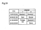
- Figure 31 illustrates a program guide which is displayed on the screen of the conventional video data reproducing apparatus which performs display of the program guide.
- the conventional video data reproducing apparatus for performing display of the program guide processes the information of the EIT (event information table) in figure 29 and displays it on a screen in a form which is visually accessible to viewer, and the viewer views the program guide displayed on screen and selects a desired broadcast program using cursor, remote control key, or the like.
- EIT event information table
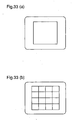
- Figures 33 are diagrams for explaining these types of services.
- Figure 33(a) illustrates digital television broadcasting which displays one program on one screen like the normal television broadcasting.
- Figure 33(b) illustrates mosaic broadcasting which obtains unique effects by splitting the screen and displaying different video images in the resultant respective blocks.
- information for identifying the types of the services has to be transmitted, for comparison with the first example.
- Figure 32 is a diagram showing the structures of the data transmitted by the video data transmission method according to the second example of the prior art technique.
- the video data of Program Number 1 and that of Program Number 3, and NIT (network information table), PMT (program map table), and EIT (event information table) as the service information are multiplexed on a packet basis within a frequency band whose center is at a receive frequency of 12.568 GHz.
- SDT Service Description Table
- SDT Service Description Table
- the data structures of the video data portions 11 and 12, and the structures of the PMT 14 and EIT 15 among as the service information are identical to those in the first example.
- the NIT includes the information about service types for the respective Program Numbers
- the SDT 16 includes information about service types and service names for the respective Program Numbers.
- the structures of the transmitting apparatus and the receiving apparatus are identical to those in the first example, and thus figure 30 is used for describing them.
- formation and transmission of multiplexed signals are performed by the video data transmitting apparatus 100 in the same manner as in the first example, and the multiplexed signal as shown in figure 32 is received by the video data reproducing apparatus 200.
- reproduction is performed in the following steps: when separating video data to transmit the same, the separating unit 2 obtains the information of the service type from the service information NIT or SDT and transmits the information to the interlaced scanning type video decoding unit 4; the interlaced scanning type video decoding unit 4 performs decoding processing dependent on whether that service type is digital broadcasting or mosaic broadcasting.
- the operations other than the above one are the same as those of the first example and therefore will not be described.
- non-interlace scanning type video data may be handled in the same manner as described when the video data transmitting apparatus is configured to form and transmit multiplexed signals using non-interlace scanning type data and the video data reproducing apparatus is configured to have a non-interlace scanning type decoding unit in place of the interlaced scanning type decoding unit.
- interlaced scanning is popular as a method for scanning pictures
- non-interlace scanning is also expected to be used increasingly in the future, and it is even thought that both interlaced scanning type video data and non-interlace scanning type video data might be supplied to a same digital broadcasting system. Therefore, it can be predicted that demands for a video reproducing apparatus capable of reproducing videos according to each of the scan methods would increase.
- the prior art video data reproducing apparatus since the prior art video data reproducing apparatus includes only one of the interlaced scanning type video decoding unit which decodes interlaced scanning type video data and the non-interlace scanning type video decoding unit which decodes non-interlace scanning type video data, the program whose scan method is different from that of the video decoding unit provided therein cannot be reproduced correctly.
- the prior art video data reproducing apparatus for performing display of the program guide displays on the screen a program guide which makes it difficult to know whether each broadcast program is of a non-interlace scanning type or of an interlaced scanning type, viewer tends to erroneously select a broadcast program of a scan method by which the video data reproducing apparatus cannot perform correct reproduction.
- the present invention which has an object to provide a video data transmitting method in which both interlaced scanning type video data and non-interlace scanning type video data can be transmitted so that the receiving end can reproduce data of both scanning types correctly, resulting in improved degree of freedom in programing of broadcast programs to be transmitted.
- the present invention has another object to provide a video data reproducing apparatus which receives a signal transmitted by the method of transmitting video data in which both interlaced scanning type video data and non-interlace scanning type video data are transmitted, reproduces both the interlaced scanning type video data and the non-interlace scanning type video data correctly, and displays the reproduced data.
- the present invention has still further object to provide a video data reproducing apparatus capable of confirming the scan method for a broadcast program to be selected when reproducing one of plural broadcast programs transmitted according to the video data transmission method in which both the interlaced scanning type video data and the non-interlace scanning type video data are transmitted, thereby preventing incorrect selection.
- Video data reproducing apparatus according to claim 1.
- a method of transmitting video data and a video data transmitting apparatus enable to multiplex and transmit pieces of video data whose scan methods are different by adding identification information to a PMT (program map table) which is service information.
- a video data reproducing apparatus is capable of reproducing the resulting multiplexed data correctly.
- Figure 1 is a construction diagram illustrating the method of transmitting video data, the video data transmitting apparatus, and the video data reproducing apparatus according to the first embodiment of the invention.
- the reference numerals shown in figure 30 designate same or corresponding parts.
- the video data transmitting apparatus further comprises a non-interlace scanning type video data storage unit 21 and an identification information storage unit 23, in addition to an interlaced scanning type video data storage unit 22.
- Reference numeral 3 designates a non-interlace scanning type video decoding unit for decoding non-interlace scanning type video data and outputs it as a video signal.
- Numeral 5 designates an identification information storage unit which stores the information about whether the video data is of an interlaced scanning type or of a non-interlace scanning type.
- Numeral 7 designates a scan method instruction unit for giving reproduce instruction to the non-interlace scanning type video decoding unit 3 or the interlaced scanning type video decoding unit 4, on the basis of the information from the identification information storage unit 5.
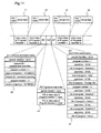
- FIG. 2 is a diagram illustrating the structure of transmission data in the method of transmitting video data according to the first embodiment.
- the difference between this and the data structure of the transmission data in the prior art transmission method shown in figure 29 resides in that a system management identifier for judging whether video data is a broadcast program or a non broadcast program can be described in the PMT (program map table) 31 and the identifier includes a code for judging whether video data is of a non-interlace scanning type or of an interlaced scanning type.
- PMT program map table
- FIG 3 is a diagram illustrating the data structure of the PMT (program map table) 31.
- the system management identifier is included in a program information descriptor in the PMT and comprises 16 bits.
- the higher order two bits are currently used for system classification, the middle order six bits for identifying techniques at notification level, and the lower order eight bits for identifying private-standard techniques which can be decided by private enterprises.
- the system classification by the higher order two bits is used for displaying whether the information of the bits lower than these higher order bits are the information available for every user or the business application information or the like. Therefore, it is possible to assign the codes indicating scan methods to the lower order eight bits and the middle order six bits, respectively, as shown in figures 4 and 5 .
- Figure 4 is a diagram illustrating an example of a code assignment to the lower order eight bits of the system management identifier.
- the code indicating interlaced scanning is 0x01
- the code indicating non-interlace scanning is 0x02. This is just an example of code assignment and any code can be applied as long as it can indicate non-interlace scanning or interlaced scanning.
- Figure 5 is a diagram illustrating an example of code assignment to the middle six bits of the system management identifier. Although in the figure it is assumed that the code indicating interlaced scanning is 1 and the code indicating non-interlace scanning is 2, the assigned codes are not limited to the above-described ones.
- Figure 6(a) is a flowchart of the procedure by the video data transmitting apparatus according to the first embodiment
- figure 6(b) is a flowchart of the procedure of the video data receiving unit (video data reproducing apparatus).
- the broadcast program of Program Number 1 is of an interlaced scanning type and the title thereof is "Quiz”
- the broadcast program of Program Number 3 is of a non-interlace scanning type and the title thereof is "Soccer”.
- a packet of the video data of Program Number 1 is formed. More specifically, 0x91 is assigned as a packet identifier PID to the header of the packet and, following the PID, the video data "Quiz" is inserted which has been obtained from the interlaced scanning type video data storage unit 22, to form a packet of a prescribed size. More specifically, the data larger than a prescribed size is divided into a plurality of packets, and for the data smaller than the prescribed size, vacant data (normally zero data) is inserted to adjust all the packets to the prescribed size.
- the PID used here is 0x91, any PID except for 0x91 is applicable as long as it is selected and given in such a way that the selected packet can be distinguished from the other packets.
- step 2 a packet of the video data of Program Number 3 is formed as in step 1.
- 0x93 is assigned as a packet identifier PID to the header of the packet, and then the video data "Soccer" is inserted which has been obtained from the non-interlace scanning type video data storage unit 21, to form the packet of a prescribed size.
- the PID is not limited to this example as in step 1.
- step 3 is executed to form a PMT packet. More specifically, 0x02 is assigned as the packet identifier PID to the header of the packet; 0X91 is assigned to the PID of the video data of Program Number 1; 0x01 is assigned, as the identification information indicating interlaced scanning, to a region comprising the lower order eight bits (0x01 indicates interlaced scanning); 0x93 is assigned to the PID of the video data of Program Number 3; and 0x02 is assigned, as the identification information indicating non-interlace scanning, to the lower order eight bits of the system management identifier (0x02 indicates non-interlace scanning).
- the middle order six bits shown in figure 5 may be used as identification information.
- the packet identifier PID of the PMT packet is defined as 0x02
- the PID of the PAT (Program Association Table) as service information may be defined in the case based on MPEG standard.
- step 4 the multiplexing unit 24 adjusts each of the formed packets to a prescribed size, outputs the packets multiplexed to the transmitting unit 25 which transmits the packets. Normally, error correction is added and QPSK modulation and QAM modulations or the like are performed before the transmission, but this is not the key point of the present invention and therefore a detailed description thereof will be omitted.
- multiplexed data is transmitted through a transmission line to the receiving unit 200 which receives the multiplexed data.
- the following procedure is performed (see figure 6(b) ).
- step 5 the receiving unit 1 receives the transmitted, multiplexed data. Then, in step 6, the separating unit 2 separates the PMT packet from the received data and extracts it, with the packet identifier PID 0x02 as the key.
- step 7 the data of the PMT obtained by the extraction in step 6 is decoded to obtain the following information: "Program Number 1: the PID of the video data is 0x91, interlaced scanning” and "Program Number 3: the PID of the video data is 0x93, non-interlace scanning", and stores the information in the identification information storage unit 5.
- step 8 the program selecting unit 6 accepts program selection from viewer through the medium of remote controller, channel buttons on a monitor or the like.
- step 9 is executed in which, according to the information obtained from the identification information storage unit 5, the program selecting unit 6 recognizes that the PID of the video data to be reproduced is 0x91 and the scan method for the data is interlaced scanning.
- the program selecting unit 6 instructs the separating unit 2 to separate a packet whose PID is 0x91, and the scan method instruction unit 7 gives decode instruction to the interlaced scanning type decoding unit 4.
- step 10 is executed.
- the program selecting unit 6 recognizes that the PID of the video data is 0x93 and the scan method for the data is non-interlace scanning, and instructs the separating unit 2 to separate a packet whose PID is 0x93, and the scan method instruction unit 7 gives decode instruction to the non-interlace scanning type decoding unit 3.
- decoding processing is performed in the interlaced scanning type decoding unit 4 in step 9 or in the non-interlace scanning type decoding unit 3 in step 10, and the resultant decoded video signal is input to the video display unit 8 and reproduced on the screen.
- both the video data whose reproduction mode is interlaced scanning and the video data whose reproduction mode is non-interlace scanning are transmitted as the pieces of video data of plural broadcast programs, and the information for judging whether the video data of a broadcast program is of an interlaced scanning type or of a non-interlace scanning type is transmitted, which information is described in a PMT (program map table) 31 indicating through which packet a broadcast program is transmitted, whereby the interlaced scanning type video data and the non-interlace scanning type video data are transmitted so that the data of each of these scan methods is reproduced correctly at the receiving end, and the video data of each of the scan methods can be processed on a broadcast program basis in contrast to the prior art method which is almost exclusive to the interlaced scanning type video data, thereby improving degree of freedom in program
- the video data transmitting apparatus comprises: the storage units 21 and 22 storing non-interlace scanning type video data and interlaced scanning type video data, respectively; the storage unit 23 for storing the information for forming service information about the video data or the like; the multiplexing unit 24 for forming and multiplexing video data packets and packets including the service information; and a transmitting unit 25 for transmitting the multiplexed data, whereby the apparatus enables to execute the above-described video transmission method and obtain the above-described effects.
- the video data reproducing apparatus comprises: the receiving unit 1 for receiving the information including at least non-interlace scanning type video data, interlaced scanning type video data, and identification data for judging whether the video data is of a non-interlace scanning type or of an interlaced scanning type; the separating unit 2 for extracting the video data selected by an operator from the information input from the receiving unit 1 and the identification information thereof; the program selecting unit 6 for accepting selection of video data from the operator and informing the separating unit 2 of the video data to be extracted; the identification information storage unit 5 for storing the identification data separated and extracted by the separating unit 2; the non-interlace scanning type video decoding unit 3 for decoding the non-interlace scanning type video data separated and extracted by the separating unit 2 and outputting it as a video signal; the interlaced scanning type video decoding unit 4 for decoding the interlaced scanning type video data separated and extracted by the separating unit 2 and outputting it as a video signal; the scan method instruction unit 7 for identifying the scan method of the video data selected
- a method of transmitting video data and a video data transmitting apparatus enable to multiplex and transmit pieces of video data of different scan methods by adding identification information to an EIT (event information table) which is service information, and a video data reproducing apparatus according to the second embodiment of the invention is capable of reproducing the resulting multiplexed data correctly.
- EIT event information table
- Figure 7 is a diagram illustrating the data structure of transmission data in the method of transmitting video data according to the second embodiment of the invention.
- component type indicating what component a broadcast program includes can be described in an EIT (event information table) 55, and the component type includes a code for judging whether video data is of a non-interlace scanning type or of an interlaced scanning type.
- Figure 8 is a diagram illustrating the data structure of the EIT (event information table) and, as shown in the figure, the component type is included in DM_component identifier as one of the descriptors in the event information table and comprises 8 bits.
- Figure 9 is a diagram illustrating an exemplary code assignment to non-interlace scanning type component type
- figure 10 is a diagram illustrating an exemplary code assignment to interlaced scanning type component type.
- these code assignments to the component types allow the information about scan methods to be transmitted along with the information about aspect ratio which indicates a length-to-width ratio of frame and the information about whether data is a moving picture or a still picture.
- the reproducing apparatus can know that the data is of a non-interlace scanning type when the given code is among 0x21 to 0x34 and that the data is of an interlaced scanning type when the given code is among 0x01 to 0x14.
- the code assignment is not limited to those shown in figures 9 and 10 and the code system to which the other information is added is applicable as long as the difference in scan methods can be recognized.
- the video data transmitting apparatus and video data reproducing apparatus according to the second embodiment have the same configurations as those according to the first embodiment, and thus figure 1 is used for the explanation.
- packets of the video data of Program Number 1 and that of Program Number 3 are formed.
- Each of plural broadcast programs included in Program Number 1 may be treated as video data of any scan method. This can be applied for Program Number 3.
- the packet of Program Number 1 comprises: “Baseball 1” obtained from the non-interlace scanning type video data storage unit 21; “Quiz” obtained from the interlaced scanning type video data storage unit 22; and “Foreign film” obtained from the non-interlace scanning type video data storage unit 21.
- the packet of Program Number 3 comprises: “Baseball 1" (interlaced scanning); “Soccer” (non-interlace scanning); “Baseball 2" (non-interlace scanning); and “News” (non-interlace scanning).
- this EIT packet and the other service information packets including the PMT describing the video data of Program Number 1, the video data of Program Number 3, and the PIDs of the video data of each Program Number are multiplexed by the multiplexing unit 24 to obtain multiplexed data.
- the resultant multiplexed data is transmitted from the transmitting unit 25.
- the procedure in which the video data reproducing apparatus 200 receives the transmitted data as shown in figure 7 and performs reproduction operation is as follows.
- the receiving unit 1 receives the transmitted multiplexed data, and the separating unit 2 separates and extracts the PMT packet with the packet identifier PID 0x02 as the key, and the EIT packet with the packet identifier PID 0x12 as the key.
- the data of the PMT is decoded to obtain the information: "the PID of the video data of Program Number 1 is 0x91” and “the PID of the video data of Program Number 3 is 0x93”, and the data of the EIT is decoded to obtain the information, e.g., "the scan method for the video data of Program Number 1 is interlaced scanning” and "the scan method for the video data of Program Number 3 is non-interlace scanning” when the current time is within a range from 20:00 to 21:00, and the obtained information is stored in the identification information storage unit 5.
- program selection from viewer is accepted through the medium of a remote controller, channel buttons of a monitor or the like and, when a viewer selects Program Number 1, it is recognized based on the information from the identification information storage unit 5 that the PID of the video data to be reproduced is 0x91 and the scan method for the data is interlaced scanning.
- the program selecting unit 6 instructs the separating unit 2 to separate a packet whose PID is 0x91, and the scan method instruction unit 7 gives decode instruction to the interlaced scanning type decoding unit 4.
- the viewer selects Program Number 3
- Program Number 3 it is recognized based on the information from the identification information storage unit 5 that the PID of the video data is 0x93 and the scan method for the data is non-interlace scanning.
- the program selecting unit 6 instructs the separating unit 2 to separate a packet whose PID is 0x93 and the scan method instruction unit 7 gives decode instruction to the non-interlace scanning type decoding unit 3.
- the video data whose reproduction mode is non-interlace scanning and the video data whose reproduction mode is interlaced scanning are transmitted as the pieces of video data of plural broadcast programs, and the information for judging whether the video data of a broadcast program is of a non-interlace scanning type or of an interlaced scanning type is transmitted, which information is described in the event information table 55 showing the contents of the video data of a broadcast program, whereby both interlaced scanning type video data and non-interlace scanning type video data can be transmitted so that the data of each of these scan methods is reproduced correctly at the receiving end, and pieces of video data of different scan methods can be processed on a broadcast program basis, resulting in improved degree of freedom in programing of broadcast programs to be transmitted.
- the video data transmitting apparatus which has the same configuration as that of the first embodiment can realize the above-described transmission method and obtain the aforesaid effects.
- the video data reproducing apparatus which has the same configuration as that of the first embodiment can correctly reproduce, on a broadcast program basis, both the non-interlace scanning type video data and the interlaced scanning type video data among the multiplexed data transmitted by the foregoing transmission method and display them.
- a method of transmitting video data and a video data transmitting apparatus can multiplex and transmit pieces of video data of different scan methods by adding identification information to an NIT (network information table) which is service information, and a video data reproducing apparatus according to the third embodiment is capable of reproducing the resulting multiplexed data correctly.
- NIT network information table
- Figure 11 is a diagram illustrating the data structure of transmission data in the method of transmitting video data according to the third embodiment of the invention.
- the difference between this and the transmission data in the prior art method shown in figure 29 is that network ID for identifying network can be described in a NIT (network information table) 63, and the network ID includes a code for judging whether video data is of a non-interlace scanning type or of an interlaced scanning type.
- NIT network information table
- Figure 12 is a diagram illustrating the data structure of the network information table indicating the presence of the network ID.
- Figure 13 is a diagram illustrating an example of code assignment to network ID. Now assume that a code indicating interlaced scanning is 0x0001 and a code indicating non-interlace scanning is 0x0002. As in the first embodiment, the code assignment is not limited to this example.
- the video data transmitting apparatus and video data reproducing apparatus according to the third embodiment have the same configuration as those according to the first embodiment and thus figure 1 is used for the description.
- video data of each broadcast program included in Program Number 1 and video data of each broadcast program included in Program Number 3 are obtained from the non-interlace scanning type storage unit and the interlaced scanning type storage unit, respectively, and video data packets of the respective programs are formed.
- the packets to which PIDs are given are formed.
- NIT packet 0x10 is assigned as PID which is the header of the NIT packet.
- PID the header of the NIT packet.
- the following data is stored in the NIT as the information about Program Number 1.
- the service information packets including the NIT, and the video data packets of Program Number 1 and Program Number 3 are multiplexed by the multiplexing unit 24, and the resultant multiplexed data is transmitted from the transmitting unit 25.
- the procedure in which the video data reproducing apparatus 200 receives the transmitted data shown in figure 11 and performs reproduction operation is as follows.
- the receiving unit 1 receives the multiplexed data transmitted and the separating unit 2 separates and extracts the PMT packet with the packet identifier PID 0x02 as the key, the NIT packet with the packet identifier PID 0x10 as the key.
- the data of the PMT is decoded to obtain the information: "the PID of the video data of Program Number 1 is 0x91” and “the PID of the video data of Program Number 3 is 0x93", and the data of the NIT is decoded to obtain the information: "the scan method for the video data of Program Number 1 is non-interlace scanning” and "the scan method for the video data of Program Number 3 is interlaced scanning", and such information is stored in the identification information storage unit 5.
- program selection from viewer is accepted through the medium of a remote controller, channel buttons of a monitor, or the like.
- Program Number 1 it is recognized based on the information from the identification information storage unit 5 that the PID of the video data to be reproduced is 0x91 and the scan method for the data is non-interlace scanning.
- the program selecting unit 6 instructs the separating unit 2 to separate a packet whose PID is 0x91 and the scan method instruction unit 7 gives decode instruction to the non-interlace scanning type decoding unit 3.
- Program Number 3 it is recognized based on the information from the identification information storage unit 5 that the PID of the video data is 0x93 and the scan method for the data is interlaced scanning.
- the program selecting unit 6 instructs the separating unit 2 to separate a packet whose PID is 0x93, and the scan method instruction unit 7 gives decode instruction to the interlaced scanning type decoding unit 4.
- video data whose reproduction mode is non-interlace scanning and video data whose reproduction mode is interlaced scanning are transmitted as the pieces of video data of plural broadcast programs and the information for judging whether the video data of a broadcast program is of a non-interlace scanning type or of an interlaced scanning type is transmitted, which information is described in the network information table 63 showing through which channel a broadcast program is transmitted, whereby interlaced scanning type video data and non-interlace scanning type video data can be transmitted such that the video data of each of these scan methods are reproduced correctly, resulting in improved degree of freedom in programing of broadcast programs to be transmitted.
- the video data transmitting apparatus configured as in the first embodiment can realize the aforesaid transmission method and obtain the above-described effects.
- the video data reproducing apparatus configured as in the first embodiment can reproduce both non-interlace scanning type video data and interlaced scanning type video data in the multiplexed data transmitted by the foregoing transmission method correctly and display them.
- a video data reproducing apparatus can selectively output video signals subjected to decoding processing of different scanning types.
- FIG 14 is a block diagram of a video data reproducing apparatus according to the fourth embodiment of the invention.
- an output switching unit 81 is added which receives video signals from the non-interlace scanning type decoding unit 3 and the interlaced scanning type decoding unit 4 and selectively outputs those video signals according to the instruction from the scan method instruction unit 7.
- the multiplexed data as shown in the first embodiment is received and, as in the first embodiment, the information about scan method transmitted in the PMT (program map table) as a service information packet is separated and extracted by the separating unit 2 and stored in the identification information storage unit 5.
- PMT program map table
- FIG. 15 is a flowchart mainly illustrating the operation of the output switching unit 81 according to the fourth embodiment. Hereinafter a description is given with reference to figure 15 .
- the scan method instruction unit 7 obtains scan information from the identification information storage unit 5, and offers the output switching unit 81 the information for non-interlace scanning when the scan information indicates non-interlace scanning, or the information for interlaced scanning when the obtained scan information indicates interlaced scanning.
- step 3 is executed and the output switching unit 81 receives the input from the non-interlace scanning type video decoding unit 3.
- step 4 is executed instead of step 3 and the output switching unit 81 receives the input from the interlaced scanning type video decoding unit 4.
- the output switching unit 81 outputs the input video signals to the video display unit 8 where the display is performed.
- a signal of a non-interlace scanning type or of an interlaced scanning type is output through a signal line to the video display unit 8. Therefore, this apparatus is effective in the case where a monitor, that is, a video display unit 8 can be used to output a video signal applied from a common terminal as a video image, whether the video signal is of a non-interlace scanning or of an interlaced scanning.
- the monitor not having such capability may be used as the video display unit 8 in the reproducing apparatus of the fourth embodiment in the following applications.
- the first application example is that the monitor corresponding to interlaced scanning only is used as the video display unit 8, and the configuration of the video data reproducing apparatus used in this application example is equal to the configuration shown in figure 14 although the output switching unit 81 operates differently.
- Figure 16 is a flowchart illustrating the operation of the first application example of the video data reproducing apparatus according to the fourth embodiment. Hereinafter a description is given of the operation of the first application example with reference to the flow of figure 16 .
- step 1 the scan method instruction unit 7 obtains scan information from the identification information storage unit 5 and informs the output switching unit 81 whether the scan information obtained indicates non-interlace scanning or interlaced scanning.
- step 4 and step 6 are executed; in step 4, the output switching unit 81 receives the input from the interlaced scanning type video decoding unit 4, and in step 6, the input is directly output to the video display unit 8.
- step 3 and step 5 are executed.
- the output switching unit 81 receives the input from the non-interlace scanning type video decoding unit 3, and in step 5, the output switching unit 81 converts the input into a signal of an interlaced scanning type and outputs the converted signal to the video display unit 8.
- step 3 or step 4 When either step 3 or step 4 is executed, the video signals output in the following step 5 and step 6 are signals of an interlaced scanning type, and the display corresponding to this scanning type is performed at the video display unit 8.
- the second application example is that a monitor corresponding to non-interlace scanning only is used as the video display unit 8, and in this application example, the video data reproducing apparatus has the same configuration as that shown in figure 14 although the output switching unit 81 operates differently.
- Figure 17 is a flowchart illustrating the operation of the second application of the video data reproducing apparatus according to the fourth embodiment. Hereinafter this operation of the second application example will be described with reference to the flow of figure 17 .
- step 1 the scan method instruction unit 7 obtains scan information from the identification information storage unit 5, and informs the output switching unit 81 whether the obtained identification information indicates non-interlace scanning or interlaced scanning.
- step 3 and step 5 are executed; in step 3, the output switching unit 81 selects the input from the non-interlace scanning type video decoding unit 3, and in step 6, the output switching unit 81 outputs the input directly to the video display unit 8.
- step 4 and step 6 are executed.
- the output switching unit 81 selects the input from the interlaced scanning type video decoding unit 4, and in step 6, the output switching unit 81 converts the input into a signal of a non-interlace scanning type and outputs the converted signal to the video display unit 8.
- step 3 or step 4 When either step 3 or step 4 is executed, the video signals output in the following step 5 and step 6 are signals of a non-interlace scanning type, and the display corresponding to this scanning type is performed at the video display unit 8.
- the non-interlace scanning type video decoding unit 3 and the interlaced scanning type video decoding unit 4 may initiate decoding after the receipt of the instruction from the scan method instruction unit 7 as described above and may continue to decode the video data from the previous stage.
- the above description is based on an assumption that the transmission data according to the first embodiment is received, but the transmission data according to the second and third embodiments may be used and the same effects may be obtained in this case although the separating unit 2 performs separation and extraction in a different way.
- the video data reproducing apparatus comprises the output switching unit 81 and therefore can select the video data subjected to decoding processing by the non-interlace scanning type video decoding unit 3 or the video data subjected to decoding processing by the interlaced scanning type video decoding unit 4 and output it as a video signal to the video display unit 8, or convert the selected data and output it, whereby video signals of different scanning types can be reproduced and displayed in both the case that a monitor used as the video display unit 8 deals with video signals of different scanning types and the case that a monitor used as the video display unit 8 deals with video signals of a single scanning type only.
- a method for transmitting video data and a video data transmitting apparatus enable to multiplex and transmit not only video data of different scanning types but program guide, and a video data reproducing apparatus according to the fifth embodiment is capable of correct reproduction of video and display of program guide to provide the information about video data.
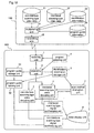
- FIG 18 is a explanatory diagram illustrating the video transmitting apparatus and video reproducing apparatus according to the fifth embodiment of the invention.
- the transmitting apparatus 100 further comprises a program guide information storage unit 26, and in this transmitting apparatus, non-interlace scanning type video data, interlaced scanning type video data, program guide information, and service information including identification information about the scanning type of each broadcast program are multiplexed in the multiplexing unit 24 and transmitted from the transmitting unit 25.
- the program guide information and the identification information about the scanning type of each broadcast program are described in an EIT (event information table) packet.
- the multiplexed data transmitted from the video data transmitting apparatus 100 of the fifth embodiment has the same structure as that transmitted from the transmitting apparatus of the second embodiment, and thus figure 7 is used for the explanation.
- the video data reproducing apparatus 200 shown in figure 18 has the configuration of the reproducing apparatus of the second embodiment (see figure 1 ) which further comprises the following elements.
- Reference numeral 51 designates a program guide storage unit for storing program guide information obtained from the EIT (event information table).
- Numeral 52 designates a program guide forming unit for processing the information from the program guide storage unit 51 into visible information.
- Numeral 9 designates an interlaced scanning type synthesizing unit for synthesizing the signals from the interlaced scanning type video decoding unit 4 and the program guide forming unit 52.
- Numeral 10 designates a non-interlace scanning type synthesizing unit for synthesizing the signals from the non-interlace scanning type video decoding unit 3 and the program guide forming unit 52.
- Figures 19 designate flowcharts respectively showing the operation of transmitting video data and the operation of reproducing video data. A description is given of the operation of the transmitting apparatus and reproducing apparatus of the fifth embodiment above configured.
- video data packets are initially formed.
- the formation method is identical to that in the second embodiment.
- These packets allow video data of different scanning types to be used as the respective broadcast programs of the respective programs (whose program numbers are 1 and 3) as in the second embodiment, although this fact is not described in detail here.
- step 1 0x12 is subjected as PID which is the header of the EIT packet, and in step 2, the following data is stored as the information about Program Number 1 in the EIT.
- step 3 the following data is stored as the information about Program Number 3 in the EIT.
- step 4 the EIT packet, the video data packets of Program Number 1 and Program Number 3, and the other service information packets including PMT which describes the PID of the video data of each Program Number are multiplexed by the multiplexing unit 24 to obtain the multiplexed data. Then, the resultant multiplexed data is transmitted from the transmitting unit 25.
- step 5 the receiving unit 1 receives the multiplexed data which is transmitted.
- step 6 the separating unit 2 separates and extracts the EIT (Event Information Table) packet with the packet identifier PID 0x12 as the key.
- step 7 the respective start times, titles, scan information of the broadcast programs of Program Number 1 and Program number 3 are decoded from the EIT and stored in the program guide storage unit 51.
- the PID of the video data obtained from the data of the PMT and the scan information of each video data from the EIT are stored in the identification information storage unit 5.
- step 8 judgment is made, and then step 9 is performed for the broadcast program for non-interlace scanning, wherein the program guide forming unit 52 registers the program title and start time of the non-interlace scanning type program guide in a program guide for non-interlace scanning type.
- step 10 is performed instead of step 9, wherein the program guide forming unit 52 registers the program title and start time of the interlaced scanning type broadcast program in a program guide for interlaced scanning type.
- the program guide forming unit 52 transmits the formed program guide to the interlaced scanning type signal synthesizing unit 9 and the non-interlace scanning type signal synthesizing unit 10, and the video display unit 8 outputs the program guide.
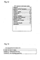
- Figure 20 is a diagram illustrating a program guide output on the screen of the display of the video data reproducing apparatus according to the fifth embodiment.
- the broadcast programs of a non-interlace scanning type and the broadcast programs of an interlaced scanning type are output separately in separate program guides. Further, these program guides may be output as a program guide as shown in figure 21 to show difference of scanning types of broadcast programs.
- step 9 After the execution of step 9 or step 10, in step 11, judgment is made whether there is left the program information to be offered and, when there is such information, this step is followed by step 8, and steps 8, 9 and 10 are repeated.
- step 12 is executed and the other process is started.
- the other process is the decoding processing of non-interlace scanning type or interlaced scanning type video data as described in the second embodiment. For example, when a viewer selects Program Number 1 in a time range from 20:00 to 21:00, it is recognized that the PID of the video data to be reproduced is 0x91 and the scan method for the data is interlaced scanning.
- the program selecting unit 6 instructs the separating unit 2 to separate a packet whose PID is 0x91, and the scan method instruction unit 7 gives decode instruction to the interlaced scanning type decoding unit 4.
- the viewer selects Program Number 3
- the PID of the video data to be reproduced is 0x93 and the scan method for the data is non-interlace scanning, based on the information stored in the identification information storage unit 5 from the contents of the PMT and EIT.
- the program selecting unit6 instructs the separating unit 2 to separate a packet whose PID is 0x93 and the scan method instruction unit 7 gives decode instruction to the non-interlace scanning type decoding unit 3.
- the video signals decoded by the interlaced scanning type decoding unit 4 and the non-interlace scanning type decoding unit 3 are input to the video display unit 8 through the interlaced scanning type signal synthesizing unit 9 and the non-interlace scanning type signal synthesizing unit 10 to be displayed on the screen.
- the method for transmitting video data according to the fifth embodiment enables to transmit multiplexed data which includes the program guide information in the EIT (event information table) as the service information, and the video data transmitting apparatus according to the fifth embodiment comprises the program guide information storage unit 26 to implement the above-described transmission method.
- the video data reproducing apparatus which selects and reproduces one of plural broadcast programs transmitted by the video data transmission method wherein plural pieces of video data of plural broadcast programs including interlaced scanning type video data and non-interlace scanning type video data are multiplexed with the event information table showing the contents of the video data of each broadcast program in each time period and the information for judging whether the video data of each broadcast program included in the event information table is of a non-interlace scanning type or of an interlaced scanning type to be transmitted, comprises the program guide outputting means for forming a program guide showing the contents of each broadcast program in each time period and the scan method for the video data and outputs the guide on the display screen as visible information, whereby the scan method for the broadcast program to be selected can be recognized, thereby preventing incorrect selection by viewer.
- the video data reproducing apparatus which comprises both the interlaced scanning type video decoding unit and the non-interlace scanning type video decoding unit and can reproduce a selected program correctly regardless of the scanning type
- the reproducing apparatus can also prevent incorrect program selection if it has a configuration capable of notifying viewer that his selection is incorrect by the medium of video display or sound display when the viewer selects a program whose scanning type does not correspond to the decoding unit of the video data reproducing apparatus.
- the reproducing apparatus can also prevent incorrect program selection if it has a configuration capable of displaying on the screen a program guide of reproducible broadcast programs.
- a method of transmitting video data and a video data transmitting apparatus enable to multiplex and transmit pieces of video data of different scan methods by adding identification information to a NIT (network information table) which is service information, and the video data reproducing unit according to the sixth embodiment is capable of reproducing the resulting multiplexed data correctly.
- NIT network information table
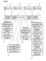
- Figure 22 is a diagram illustrating the data structure of transmission data in the method of transmitting video data of the sixth embodiment.
- the difference between this and the transmission data shown in figure 32 according to the prior art method (second example) is that "program list" is included among the descriptors within the NIT (network information table) 73 and the program list includes "service type" which is a code indicating whether video data is of an interlaced scanning type or of a non-interlace scanning type.
- Figure 23 is a diagram illustrating the data structure of the NIT (network information table).
- Figure 24 illustrates an example of code assignment to the service type of the service list.
- codes 0x01 to 0x04 indicate interlaced scanning and codes 0x05 to 0x08 indicate non-interlace scanning.
- codes 0x01 to 0x04 indicate interlaced scanning and codes 0x05 to 0x08 indicate non-interlace scanning.
- NVOD Near Video On Demand
- the code assignment is not limited to this example, as in the first embodiment.
- the video data transmitting apparatus and video data reproducing apparatus according to the sixth embodiment have the same configurations as those of the first embodiment, and thus figure 1 is used for the explanation.
- video data of each broadcast program included in Program Number 1 and that of each broadcast program included in Program Number 3 are obtained from the non-interlace scanning type storage unit and the interlaced scanning type storage unit, respectively, to form the video data packets of the respective programs.
- the packets to which PIDs are given are formed by the same method used in the first embodiment.
- NIT packet A description is given of the NIT packet here.
- 0x10 is assigned as the PID which is the header of the NIT packet, and the following data is stored in the NIT as the information about Program Number 1.
- the service information packets including this NIT, the video data packets of Program Number 1 and Program Number 3 are multiplexed by the multiplexing unit 24 and the resultant multiplexed data is transmitted from the transmitting unit 25.
- the procedure in which the video data reproducing apparatus 200 receives the transmission data shown in figure 22 and performs the reproduction operation is as follows.
- the receiving unit 1 receives the multiplexed data which is transmitted and the separating unit 2 separates and extracts the PMT packet with the packet identifier PID 0x02 as the key and the NIT packet with the packet identifier PID 0x10 as the key.
- the data of the PMT is decoded to obtain the information: "the PID of the video data of Program Number 1 is 0x91” and “the PID of the video data of Program Number 3 is 0x93", and the data of the NIT is decoded to obtain the information: "the scan method for the video data of Program Number 1 is non-interlace scanning” and "the scan method for the video data of Program Number 3 is interlaced scanning", and the information obtained is stored in the identification information storage unit 5.
- program selection from viewer is accepted by the medium of a remote controller or channel buttons of a monitor, and when a viewer selects Program Number 1, it is recognized that the PID of the video data to be reproduced is 0x91 and the scan method for the data is non-interlace scanning.
- the program selecting unit 6 instructs the separating unit 2 to separate a packet whose PID is 0x91 and the scan method instruction unit 7 gives decode instruction to the non-interlace scanning type decoding unit 3.
- Program Number 3 it is recognized that the PID of this video data is 0x93 and the scan method for the data is interlaced scanning, on the basis of the information from the identification information storage unit 5.
- the program selecting unit 6 instructs the separating unit 2 to separate a packet whose PID is 0x93 and the scan method instruction unit 7 gives decode instruction to the interlaced scanning type decoding unit 4.
- the video data transmitting apparatus of the sixth embodiment having the same configuration as the transmitting apparatus of the first embodiment can implement the above-described transmission method and obtain the above-described effects.
- the video data reproducing apparatus of the sixth embodiment has the same configuration as that of the first embodiment and can correctly reproduce the non-interlace scanning type video data and the interlaced scanning type video data in the multiplexed data transmitted by the transmission method and reproduce them.
- a method of transmitting video data and a video data transmitting apparatus enable to multiplex and transmit pieces of video data of different scan methods by adding the identification information to a SDT (service description table) which is service information, and a video data reproducing apparatus according to this embodiment is capable of reproducing the resulting multiplexed data correctly.
- SDT service description table
- Figure 25 is a diagram illustrating a data structure of transmission data in the method of transmitting video data of the seventh embodiment.
- SDT service description table
- service type which is a code indicating whether video data is of a non-interlace scanning type or of an interlaced scanning type.
- the data structure of the SDT (service table) consists of program number, service type, and name of program.
- the exemplary code assignment of the sixth embodiment shown in figure 24 may be used as the code assignment to service type and it is assumed here that codes 0x0001 to 0x004 indicate interlaced scanning and codes 0x0005 to 0x008 indicate non-interlace scanning.
- the code arrangement is not limited to this example, as in the first embodiment.
- the video data transmitting apparatus and video data reproducing apparatus according to the seventh embodiment have the same configuration as those of the first embodiment, and thus figure 1 is used for the explanation.
- video data of each broadcast program included in Program Number 1 and video data of each broadcast program included in Program Number 3 are obtained from the non-interlace scanning type storage unit and the interlaced scanning type storage unit, respectively, to form the video data packets of the respective programs.
- the packets to which PIDs are given are formed in the same manner used in the first embodiment.
- the service information packets including this SDT packet and the video data packets of Program Number 1 and Program Number 3 are multiplexed by the multiplexing unit 24 and the resulting multiplexed data is transmitted from the transmitting unit 25.
- the procedure in which the video data reproducing apparatus 200 receives the transmission data shown in figure 25 and performs reproduction operation is as follows.
- the receiving unit 1 receives the multiplexed data transmitted, and the separating unit 2 separates and extracts the PMT packet with the packet identifier PID 0x02 as the key and the SDT packet with the packet identifier PID 0x11 as the key.
- the data of the PMT is decoded to obtain the information: "the PID of the video data of Program Number 1 is 0x91” and “the PID of the video data of Program Number 3 is 0x93", and the data of the SDT is decoded to obtain the information: "the scan method for the video data of Program Number 1 is non-interlace scanning” and "the scan method for the video data of Program Number 3 is interlaced scanning", and such information is stored in the identification information storage unit 5.
- program selection from viewer is accepted through the medium of remote controller or channel buttons of a monitor, and when a viewer selects Program Number 1, it is recognized on the basis of the information from the identification information storage unit 5 that the PID of the video data to be reproduced is 0x91 and the scan method for the data is non-interlace scanning.
- the program selecting unit 6 instructs the separating unit 2 to separate a packet whose PID is 0x91, and the scan method instruction unit 7 gives decode instruction to the non-interlace scanning type decoding unit 3.
- Program Number 3 it is recognized on the basis of the information from the identification information storage unit 5 that the PID of the video data is 0x93 and the scan method for the data is interlaced scanning.
- the program selecting unit 6 instructs the separating unit 2 to separate a packet whose PID is 0x93, and the scan method instruction unit 7 gives decode instruction to the interlaced scanning type decoding unit 4.
- the video data transmitting apparatus comprising the same configuration as that of the first embodiment can implement the above-described transmission method and obtain the aforesaid effects.
- the video data reproducing apparatus of the seventh embodiment has the same configuration as that of the first embodiment and can correctly reproduce both the non-interlace scanning type video data and the interlaced scanning type video data in the multiplexed data transmitted by the above-described transmission method, and display the reproduced data.
- a method of transmitting video data and a video data transmitting apparatus enable to multiplex and transmit pieces of video of different scan methods on a broadcast program basis by adding identification information to a NIT (network information table) which is service information, and a video data reproducing apparatus according to the eighth embodiment is capable of reproducing the resulting multiplexed data correctly.
- NIT network information table
- Figure 26 is a diagram illustrating a data structure of transmission data in the method of transmitting video data of the eighth embodiment.
- the differences between this and the transmission data in the prior art method (second example) shown in figure 32 are the following points: one point is that "program list" is among the descriptors included in the NIT (network information table) 73 and the program list includes service type which is a code indicating whether video data is of a non-interlace scanning type or of an interlaced scanning type; the other point is that "component type” indicating components of broadcast program can be described in the EIT (event information table) 85, and in some programs, a code for judging whether video data is of a non-interlace scanning type or of an interlaced scanning type is included in the component type.
- the data structure of the NIT (network information table) shown in figure 23 is equal to that of the sixth embodiment.
- Figure 27 illustrates an example of a code assignment to service type in the service list.
- codes 0x01 to 0x04 indicate interlaced scanning and codes 0x05 to 0x08 indicate non-interlace scanning and, codes 0x11 to 0x14 are assigned to programs each including broadcast programs of different scan methods.
- the code arrangement is not restricted to the example shown here as in the first embodiment.
- the video data transmitting apparatus and video data reproducing apparatus according to the eighth embodiment have the same configuration as those of the first embodiment, thus figure 1 is used for the explanation.
- the transmitting apparatus 100 forms video data packets. Broadcast programs included in each program may be of a same scanning type on a program basis, and a program including broadcast programs of different scan methods may be used.
- the pieces of video data including non-interlace scanning type video data and interlaced scanning type video data are used for the broadcast programs included in Program Number 1 and packets are formed from the following pieces of video data: "Baseball 1" obtained from the non-interlace scanning type video data storage unit 21, "Quiz” obtained from the interlaced scanning type video data storage unit 22, and "Foreign film” obtained from the non-interlace scanning type video data storage unit 21.
- it is the non-interlace scanning type video data only which is employed for the broadcast programs included in Program Number 3.
- the pieces of video data are obtained from the respective storage units, and the video data packets of the respective programs to which PIDs are given are formed in the same manner used in the first embodiment.
- service information packets are formed.
- the EIT packet is formed after the formation of the NIT packet. Initially, the NIT packet is formed. 0x10 is assigned as the PID which is the header of the NIT packet. Then, the following data is stored as the information about Program Number 1 in a service list which is included as a descriptor.
- EIT packet is formed. Initially, 0x12 is assigned as the PID which is the header of the EIT packet. Since the scan methods of the broadcast programs are mixed in Program Number 1, the following data is then stored as the information about Program Number 1 in the EIT.
- Program Number 3 comprises non-interlace scanning type broadcast programs only
- the following data is stored in the EIT as the information about this program.
- the EIT packet is formed without giving a code indicating a scan method to the component type.
- the service information packets including the NIT and the EIT, the video data packets of Program Number 1 and Program Number 3 are multiplexed by the multiplexing unit 24, and the resulting multiplexed data is transmitted from the transmitting unit 25.
- the procedure in which the video data reproducing apparatus 200 receives the transmission data shown in figure 26 and performs reproduction operation is as follows.
- the receiving unit 1 receives the multiplexed data which is transmitted, and the separating unit 2 separates and extracts the PMT packet with the packet identifier PID 0x02 as the key and the NIT packet with the packet identifier PID 0x10 as the key, and the EIT packet with the packet identifier PID 0x12 as the key.
- the data of the PMT is decoded to obtain the information: "the PID of the video data of Program Number 1 is 0x91" and "the PID of the video data of Program Number 3 is 0x93", and such information is stored in the identification information storage unit 5.
- the data of the NIT is decoded to obtain the information: "the scan method for the video data of Program Number 1 is mixed scanning” and "the scan method for the video data of Program Number 3 is non-interlace scanning".
- the data of the EIT is decoded to obtain the information, for example, "the scan method for the video data of Program Number 1 is interlaced scanning", when the current time is within a time range from 20:00 to 21:00, and this information is stored with the previously obtained information that the scan method for the video data of Program Number 3 is non-interlace scanning" in the identification information storage unit 5.
- program selection from viewer is accepted through the medium of a remote controller and channel buttons of a monitor and, when a viewer selects Program Number 1, it is recognized on the basis of the information from the identification information storage unit 5 that the PID of the video data to be reproduced is 0x91 and the scan method for this data is interlaced scanning.
- the program selecting unit 6 instructs the separating unit 2 to separate a packet whose PID is 0x91 and the scan method instruction unit 7 gives decode instruction to the interlaced scanning type decoding unit 4.
- Program Number 3 it is recognized on the basis of the information from the identification information storage unit 5 that the PID of the video data is 0x93 and the scan method for the data is non-interlace scanning.
- the program selecting unit 6 instructs the separating unit 2 to separate a packet whose PID is 0x93 and the scan method instruction unit 7 gives decode instruction to the non-interlace scanning type decoding unit 3.
- video data whose reproduction mode is non-interlace scanning on a broadcast program basis and video data whose reproduction mode is interlaced scanning on a broadcast program basis are transmitted as the pieces of video data of plural broadcast programs, and the information for judging whether video data is of a non-interlace scanning type or of an interlaced scanning type, or of a mixed scanning type is transmitted, which information is described in the network information table 73 indicating through which channel a broadcast program is transmitted, and for the program whose scan method is a mixed scanning, the information for identifying the scan method for the video data of each broadcast program is transmitted, which information is described in the event information table 85 indicating the contents of the video data of each broadcast program in each time period, whereby both the interlaced scanning type video data and the non-interlace scanning type video data can
- describing the scan methods in the event information table 85 is omitted for the program whose broadcast programs are of a same scanning type while this description is performed for the program in which scan method differs from broadcast program to broadcast program, whereby the amount of information to be transmitted is reduced compared with the case of performing the description for the broadcast programs of all the programs, resulting in reduction in transmission rate, processing load, and processing time.
- the video data transmitting apparatus which has the same configuration as that of the first embodiment can implement the above-described transmission method and obtain the aforesaid effects.
- the video data transmitting apparatus which has the same configuration as that of the first embodiment can reproduce both the non-interlace scanning type video data and the interlaced scanning type video data in the multiplexed data transmitted by the foregoing transmission method and display the reproduced data.
- a method of transmitting video data and a video data transmitting apparatus enable to multiplex and transmit pieces of video data of different scan methods on a broadcast program basis by adding identification information to a SDT (service description table) which is service information, and a video data reproducing apparatus according to the ninth embodiment is capable of reproducing the resultant multiplexed data correctly.
- SDT service description table
- Figure 28 is a diagram illustrating a data structure of transmission data in the method of transmitting video data of the ninth embodiment.
- the differences between this and the transmission data in the second prior art method shown in figure 32 are as follows: one point is that the SDT (service description table) 76 includes service type which is a code indicating whether video data is of a non-interlace scanning type or of an interlaced scanning type; the other point is that component type indicating the components of broadcast program can be described into the EIT (event information table) 85, and in some programs, the component type includes a code for judging whether video data is of a non-interlace scanning type or of an interlaced scanning type.
- the data structure of the SDT (service description table) is equal to that of the seventh embodiment, and the assignment of the service codes in the service list is equal to that of the eighth embodiment. Therefore, the service type codes are equal to those shown in figure 27 and codes 0x01 to 0x04 indicate interlaced scanning and codes 0x05 to 0x08 indicate non-interlace scanning and, programs each including broadcast programs of different scan methods are assigned codes 0x11 to 0x14.
- the code assignment is not restricted to this example as in the first embodiment.
- the video data transmitting apparatus and video data reproducing apparatus according to the ninth embodiment have the same configuration as those of the first embodiment, and thus figure 1 is used for the explanation.
- video data packets are formed.
- the broadcast programs included in each program may be of a same scanning type on a program basis, and programs including broadcast programs of different scan methods may be applied.
- pieces of video data of different scan methods that is, non-interlace scanning type video data and interlaced scanning type video data are employed for the broadcast programs included in Program Number 1, and packets are formed from the following pieces of data: "Baseball 1" obtained from the non-interlace scanning type video data storage unit 21, "Quiz” obtained from the interlaced scanning type video data storage unit 22, and "Foreign film” obtained from the non-interlace scanning type video data storage unit 21.
- Program Number 3 employed is non-interlace scanning type video data only.
- the pieces of video data are obtained from the respective storage units, and the video data packets of the respective programs to which PIDs are added are formed in the same method used in the first embodiment.
- the EIT packet is formed after the formation of the SDT packet. Initially, the SDT packet is formed. 0x11 is assigned as the PID which is the header of the SDT packet. Then, the following data is stored in the SDT as the information about Program Number 1.
- EIT packet is formed. Initially, 0x12 is assigned as the PID which is the header of the EIT packet. Then, since Program number 1 includes broadcast programs of different scan methods, the following data is stored as the information about the program in the EIT.
- Program Number 3 comprises non-interlace scanning type broadcast programs only
- the following data is stored in the EIT as the information about the program.
- EIT packet is formed without giving a code indicating scan method to the component type.
- the service information packets including the NIT and the EIT, the video data packets of Program Number 1 and Program Number 3 are multiplexed by the multiplexing unit 24, and the resultant multiplexed data is transmitted from the transmitting unit 25.
- the procedure in which the video data reproducing apparatus 200 receives the transmission data shown in figure 28 and performs reproduction operation is as follows.
- the receiving unit 1 receives the multiplexed data transmitted, and the separating unit 2 separates and extracts the PMT packet with the packet identifier PID 0x02 as the key and the SDT packet with the packet identifier PID 0x11 as the key, and the EIT packet with the packet identifier PID 0x12 as the key.
- the data of the PMT is decoded to obtain the information: "the PID of the video data of Program Number 1 is 0x91" and "the PID of the video data of Program Number 3 is 0x93", and such information is stored in the identification information storage unit 5.
- the data of the SDT is decoded to obtain the information: "the scan method for the video data of Program Number 1 is mixed scanning” and "the scan method for the video data of Program Number 3 is non-interlace scanning".
- the data of the EIT is decoded to obtain the information, for example, "the scan method for the video data of Program Number 1 is interlaced scanning", when the current time is within a time range from 20:00 to 21:00, and this information is stored with the previously obtained information that the scan method for the video data of Program Number 3 is non-interlace scanning in the identification information storage unit 5.
- program selection from viewer is accepted through the medium of a remote controller or channel buttons of a monitor and, when a viewer selects Program Number 1, it is recognized on the basis of the information from the identification information storage unit 5 that the PID of the video data to be reproduced is 0x91 and the scan method for this data is interlaced scanning.
- the program selecting unit 6 instructs the separating unit 2 to separate a packet whose PID is 0x91 and the scan method instruction unit 7 gives decode instruction to the interlaced scanning type decoding unit 4.
- Program Number 3 it is recognized on the basis of the information from the identification information storage unit 5 that the PID of the video data is 0x93 and the scan method for the data is non-interlace scanning.
- the program selecting unit 6 instructs the separating unit 2 to separate a packet whose PID is 0x93 and the scan method instruction unit 7 gives decode instruction to the non-interlace scanning type decoding unit 3.
- the video data whose reproduction mode is non-interlace scanning on a broadcast program basis and the video data whose reproduction mode is interlaced scanning on a broadcast program basis are transmitted as the pieces of video data of plural broadcast programs, and the information for judging whether video data is of a non-interlace scanning type, of an interlaced scanning type, or of a mixed scanning type is transmitted, which information is described in the service description table 76 containing the name and service type of each program, and for the program whose scan method is mixed scanning, the information for identifying the scan method for each broadcast program is transmitted, which information is described in the event information table 85 indicating the content of the video data of each broadcast program in each time period, whereby both interlaced scanning type video data and non-interlace scanning type video data can be transmitted so that the video data
- describing the scan method in the event information table 85 is omitted for a program including broadcast programs of same scan method while this description is performed for a program including broadcast programs of different scan methods, whereby the amount of information to be transmitted can be reduced compared with the case of performing description to the broadcast programs of every program, resulting in reduction in transmission rate, cost of processing, and processing time.
- the video data transmitting apparatus which has the same configuration as that of the first embodiment can implement the above-described transmission method and obtain the aforesaid effects.
- the video data transmitting apparatus which has the same configuration as that of the first embodiment can reproduce both the non-interlace scanning type video data and the interlaced scanning type video data in the multiplexed data transmitted by the foregoing transmission method correctly and display them.
- the video data reproducing apparatus may have the configuration as those of the fourth embodiment which comprises an output switching unit, whereby video data of either scan method can be reproduced corresponding to the performance of the video display unit as in the fourth embodiment.
- the video data transmitting apparatus may transmit the program guide information as shown in the fifth embodiment and thus display the same program guide as that of the fifth embodiment, preventing the incorrect selection operation by viewer.
- plural pieces of video data of plural broadcast programs are respectively divided into packets and the plural packets of the video data and packets including information about the broadcast programs are multiplexed and transmitted, video data whose reproduction mode is non-interlace scanning and video data whose reproduction mode is interlaced scanning are transmitted as the pieces of video data of plural broadcast programs, and the information for judging whether the video data of a broadcast program is of a non-interlace scanning type or of an interlaced scanning type being described in the packets including the information about the broadcast programs is transmitted, whereby the non-interlace scanning type video data and the interlaced scanning type video data can be transmitted such that the video data of each of these scan methods is correctly reproduced and displayed at the receiving end, resulting in improved degree of freedom in programing of broadcast programs to be transmitted.
- the information for identifying the scan method of the video data is given to each broadcast program included in each program, whereby pieces of data of different scanning types can be present in a program, resulting in greatly improved degree of freedom in programing of broadcast programs to be transmitted can be improved greatly, improved efficiency in forming transmission data, and reduced transmission rate for transmission data.
- a video data transmitting apparatus of claim 14 which divides plural pieces of video data of plural broadcast programs into packets, respectively, and multiplexes and transmits the plural packets of the video data and packets including information about the broadcast programs, comprises: a multiplexing unit for multiplexing packets of video data whose reproduction mode is non-interlace scanning and packets of video data whose reproduction mode is interlaced scanning, and packets including the information about the broadcast programs, which information includes the information for judging whether video data is of a non-interlace scanning type or of an interlaced scanning type; and a transmitting unit for transmitting the transmission data multiplexed by the multiplexing unit, whereby both non-interlace scanning type video data and interlaced scanning type video data can be transmitted such that the pieces of video data of different scan methods are reproduced correctly at the receiving end, resulting in improved degree of freedom in programing of broadcast programs to be transmitted.
- a video data reproducing apparatus of claim 15 comprises: a receiving unit for receiving the information including at least non-interlace scanning type video data, interlaced scanning type video data, and identification data for judging whether the video data is of a non-interlace scanning type or of an interlaced scanning type; a separating unit for extracting video data which is selected by operator and the identification data from the information input from the receiving unit; a program selecting unit for accepting the selection of video data by the operator and informing the separating unit of the video data to be extracted; an identification information storage unit for storing the identification data separated and extracted by the separating unit; a non-interlace scanning type decoding unit for decoding the non-interlace scanning type video data separated and extracted by the separating unit and outputting the same as a video signal; an interlaced scanning type decoding unit for decoding the interlaced scanning type video data separated and extracted by the separating unit and outputting the same as a video signal; and a scanning instruction unit for identifying the video scan method of the video data selected by the operator based on the information in
- the apparatus of claim 15 further includes an output switching unit for receiving the respective video signals from the non-interlace scanning type video decoding unit and the interlaced scanning type video decoding unit, and selectively outputting the video signal from the non-interlace scanning type video decoding unit or that from the interlaced scanning type video decoding unit, on the basis of the instruction from the scan method instruction unit, whereby video data of each of the scan methods can be correctly reproduced at a display unit conforming to both of the scan methods.
- the output switching unit directly outputs video data of a scan method while it converts video data of another scan method to that of the aforesaid scan method and outputs the converted data, whereby video data of each of the scan methods can be correctly reproduced at a display unit conforming to one of the scan methods.
- a video data reproducing apparatus of claims 19 and 21 which selects and reproduces one of plural broadcast programs transmitted by a method of transmitting video data wherein plural pieces of video data of plural broadcast programs including interlaced scanning type video data and non-interlace scanning type video data are multiplexed along with an event information table indicating the contents of the video data of each broadcast program in each time period and the information for judging whether the video data of each broadcast program included in the event information table is of a non-interlace scanning type or of an interlaced scanning type to be transmitted, further comprises a program guide forming means for forming a program guide showing the contents of each broadcast program in each time period and the scan method of the video data based on the event information table and the identification information and outputting the program guide on a display screen of a video display unit as visible information, whereby the scan method of a broadcast program to be selected can be confirmed and thus incorrect selection can be prevented.
- the apparatus of any of claims 19 to 21 further comprises a notification unit for notifying, as visible information or audible information, that video reproduction is impossible when a broadcast program is selected incapable of being reproduced by this reproducing apparatus because of the scan method of the video data of the selected broadcast program, whereby incorrect selection by viewer can be prevented more effectively.
- the program guide forming means displays broadcast programs reproducible by the reproducing apparatus because the scanning type of the broadcast programs agrees to that of the reproducing apparatus, whereby incorrect selection by viewer can be prevented more effectively.
Landscapes
- Engineering & Computer Science (AREA)
- Multimedia (AREA)
- Signal Processing (AREA)
- Television Systems (AREA)
- Two-Way Televisions, Distribution Of Moving Picture Or The Like (AREA)
- Television Signal Processing For Recording (AREA)
- Color Television Systems (AREA)
Abstract
Description
- The present invention relates to a method of transmitting video data, a video data transmitting apparatus, and a video data reproducing apparatus. More particularly, it relates to a method of transmitting video data, a video data transmitting apparatus, and a video data reproducing apparatus for identifying pieces of video data whose video reproduction modes are different to reproduce the same.
- For television broadcasting, it is essential that videos, i.e., moving pictures are converted into television signals and transmitted, and a receiver receives these signals and performs reproduction processing to obtain the moving pictures and display them. In the case of sound signal which allows to treat a relation between time and sound pressure as one-dimensional one, instantaneous sound pressures (during a short time period) can be directly converted into electric signals. On the other hand, in the case of moving picture, if it is partitioned into still pictures at short time intervals, each still picture is planar, that is, two-dimensional information and therefore it is necessary to, prior to the conversion into signals, make their planes one-dimensional by scanning, so that the plane can be treated as a plurality of scan lines. Scan methods for obtaining a plurality of scan lines from pictures includes non-interlace scanning and interlaced scanning. Non-interlace scanning is a method in which all of the scan lines on a frame (a screen) are sequentially scanned from top to bottom to display a video image, and interlaced scanning is a method in which every other scan line is scanned.
- When the display performance of a display device is not so high, non-interlace scanning causes flicker on screen due to the increase of the time difference between the top and the bottom of the scanning. Therefore, interlaced scanning is mainly employed in the conventional television broadcasting. In the NTSC system which is known as a common television system, assuming that one frame (screen) consists of 525 scan lines, two kinds of scanning, scanning for odd lines and scanning for even lines are performed, which means that two fields are scanned.
- If the display device has a high display performance, however, the flicker on screen can be reduced by means of non-interlace scanning. Generally, a number of display times per second for a non-interlace scanning type computer display is approximately a double of the number of display times per second for an interlace scanning type one. Therefore, non-interlace scanning has captured much of the spotlight in the field of high-definition television or the like because it enables superior picture quality and high affinity for CG (computer graphics) or the like.
- On the other hand, when moving pictures are digitized to be recorded and transmitted or received as digital data, the digitized data is generally treated as compressed code. As standardized moving picture compression technique, most common is MPEG (Moving Picture Experts Group), which is described in Latest Manual of MPEG (Ascii Co., Ltd, First Edition, published on August 1, 1994) and Practical Manual of MPEG (Ascii Co., Ltd, First Edition, Published by November 1, 1995). These books also refer to the well-known transmission and reception methods for video data and video data reproducing apparatuses on the basis of MPEG standard.
- In the prior art, techniques for transmitting and receiving video data based on MPEG standard have been established on the assumption that video data based on interlaced scanning is exclusively used because interlaced scanning is common in television broadcasting as described above. On the other hand, in the case of using videos based on non-interlace scanning, developments and the like have been developed on the assumption that video data subjected to non-interlace scanning is exclusively used.
- The following description is on the conventional transmission and reception of video data using video image subjected to interlaced scanning which is common in television broadcasting or the like. As a first example of the prior art technique, a system for providing digital television broadcasting is described.
-
Figure 29 is a diagram illustrating a structure of the data transmitted by the method of transmitting and receiving video data according to the first example of the prior art. As shown in the figure, video data ofProgram Number 1, video data ofProgram Number 3, and service information such as NIT (Network Information Table), PMT (Program Map Table), EIT (Event Information Table) are multiplexed on a packet basis within a band whose center is at a receive frequency of 12.568 GHz. In digital data transmission based on MPEG standard, since a plurality of programs (which correspond to channels in normal analog broadcasting) can be multiplexed and transmitted, the above-described pieces of service information are used to select a desired broadcast program in a desired program from the multiplexed transmission data, and these pieces of service information are thus multiplexed with the data to be transmitted. - Although the data structure of these packets and the standards on multiplexing of the packets are defined in detail in MPEG, here a description is given only of the portions particularly related.
-
Reference numeral 11 designates a packet of video data of Program Number 1 (channel 1). The packet identifier PID as the header is defined as 0x91 so that this packet can be identified as the packet of the video data ofProgram Number 1.Reference numeral 12 designates a packet of video data of Program Number 3 (channel 3). The packet identifier PID as the header is defined as 0x93 so that this packet can be identified as the packet of the video data ofProgram Number 3. -
Reference numerals 13 to 15 designate packets of service information.Reference numeral 13 designates NIT (Network Information Table) packet which defines respective frequencies on which the video data ofProgram Number 1 and that ofProgram Number 3 are transmitted. This example shows that both the video data ofProgram Number 1 and that ofProgram Number 3 are multiplexed in the band of 12.568 GHz.Reference numeral 14 designates a PMT (program map table) packet. This example shows that the video data ofProgram Number 1 is included in a packet whose packet identifier is 0x91, the video data ofProgram Number 3 is included in a packet whose packet identifier is 0x93.Reference numeral 15 designates an EIT (event information table) packet. This example shows that inProgram Number 1, "Baseball 1" will be aired from 19:00 to 20:00, "Quiz" from 20:00 to 21:00, and "Foreign film" from 21:00, and that inProgram Number 3, "Baseball 1" will be aired from 19:00 to 20:00, "Soccer" from 20:00 to 21:00, "Baseball 2" from 21:00 to 22:00, and "News" from 22:00. -
Figure 30 is a diagram illustrating a prior art method of transmitting video data. Referring to the figure,numeral 100 designates a video data transmitting apparatus which is at a transmitting end, andnumeral 200 designates a video data reproducing apparatus which is at a receiving end. In the videodata transmitting apparatus 100,reference numeral 22 designates a video data storage unit for storing interlaced scanning type video data. Numeral 24 designates a multiplexing unit for multiplexing interlaced scanning type video data and the information relative to the data. Numeral 25 designates a transmitting unit for transmitting the signals multiplexed by themultiplexing unit 24. In the videodata reproducing apparatus 200,reference numeral 1 designates a receiving unit for receiving the transmitted multiplexed signal, i.e., the signal shown infigure 22 consisting of the video data ofProgram Number 1, the video data ofProgram Number 3, NIT, PMT, and EIT.Reference numeral 2 designates a separating unit for separating the multiplexed signals received by thereceiving unit 1,numeral 6 designates a program selecting unit for accepting selection operation of broadcast program from viewer and informing the receivingunit 1 and theseparating unit 2 of the selected broadcast program. As theprogram selecting unit 6, widely-used popular selector may be employed such as a remote controller for selecting television program, channel buttons of a television receiver or a mouse of a personal computer.Reference numeral 4 designates an interlaced scanning type video decoding unit for decoding interlaced scanning type video data separated by the separatingunit 2 and outputting the decoded data as a video signal. - Common video data reproducing apparatus further requires, other than the above, various components such as a decoding unit for decoding audio data. However, since these are not directly related to the present invention, they are not described for the sake of simplicity of explanation.
- Next, the operations of the prior art video data transmitting apparatus and the prior art video data reproducing apparatus will be described.
- Initially, in the video
data transmitting apparatus 100, themultiplexing unit 24 multiplexes the interlaced scanning type video data ofProgram Number 1 and that ofProgram Number 3, and NIT, PMT, and EIT as the service information in packets of predetermined bit lengths as shown infigure 29 , followed by the transmission from the transmittingunit 25. - The transmitted multiplexed signal is sent through a transmission medium such as electric wave or cable to viewer's reproducing apparatus where the viewer can utilize the signal. In the video
data reproducing apparatus 200, video data is reproduced as follows. - First of all, the
program selecting unit 6 accepts selection operation of broadcast program from viewer and informs the receivingunit 1 of the broadcast program designated according to the selection. This designation may be done directly by switching or inputting a numerical value as in the case of designating channel at a normal television receiver, and the selection may be carried out through a visual interface such as a program table which will be later described. - The
receiving unit 1 receives a signal of a frequency on which the video data of the designated broadcast program (Program Number) is transmitted. Since a transmission signal of any receive frequency is multiplexed with an NIT of the same contents to be transmitted, thereceiving unit 1 recognizes, from the contents described in the NIT, on which receive frequency the video data of the designated Program Number is transmitted, to perform selection of receive frequency. - The separating
unit 2 separates video data from the information received by thereceiving unit 1, according to theprogram selecting unit 6. More specifically, if theprogram selecting unit 6 instructs to reproduce the data ofProgram Number 1, the separating unit recognizes that the packet identifier PID of the video data ofProgram Number 1 is 0x91 from the contents of the PMT, and extracts a packet whose packet identifier PID is 0x91, and transmits it to the next stage. If it is instructed to reproduce the data ofProgram Number 3, as in the above case, the separating unit recognizes that the packet identifier PID of the video data ofProgram Number 3 is 0x93 from the contents of the PMT, extracts a packet whose packet identifier PID is 0x93, and transmits it to the next stage. - Thereby, the target video data is processed to reproduce a desired video. The interlaced scanning type
video decoding unit 4 decodes the video data separated by the separatingunit 2 in interlaced scanning mode to output it as a video signal, and thevideo display unit 8 receives the video signal output from the interlaced scanning typevideo decoding unit 4 as an input and displays a video image corresponding to the input signal on the screen. -
Figure 31 illustrates a program guide which is displayed on the screen of the conventional video data reproducing apparatus which performs display of the program guide. The conventional video data reproducing apparatus for performing display of the program guide processes the information of the EIT (event information table) infigure 29 and displays it on a screen in a form which is visually accessible to viewer, and the viewer views the program guide displayed on screen and selects a desired broadcast program using cursor, remote control key, or the like. - Next, a description is given of a second example of the prior art technology which is a system for providing plural types of services, for example, two types of services comprising digital television broadcasting and mosaic broadcasting.
Figures 33 are diagrams for explaining these types of services.Figure 33(a) illustrates digital television broadcasting which displays one program on one screen like the normal television broadcasting.Figure 33(b) illustrates mosaic broadcasting which obtains unique effects by splitting the screen and displaying different video images in the resultant respective blocks. In this example, information for identifying the types of the services has to be transmitted, for comparison with the first example. -
Figure 32 is a diagram showing the structures of the data transmitted by the video data transmission method according to the second example of the prior art technique. Similarly as in the first example, the video data ofProgram Number 1 and that ofProgram Number 3, and NIT (network information table), PMT (program map table), and EIT (event information table) as the service information are multiplexed on a packet basis within a frequency band whose center is at a receive frequency of 12.568 GHz. In the present example, SDT (Service Description Table) is also multiplexed on a packet basis. - Referring to
figure 32 , the data structures of thevideo data portions PMT 14 andEIT 15 among as the service information are identical to those in the first example. In this present example, the NIT includes the information about service types for the respective Program Numbers, and theSDT 16 includes information about service types and service names for the respective Program Numbers. - Also in the second example, the structures of the transmitting apparatus and the receiving apparatus are identical to those in the first example, and thus
figure 30 is used for describing them. - A description is given of the operations of the video
data transmitting apparatus 100 and the videodata receiving apparatus 200. Initially, formation and transmission of multiplexed signals are performed by the videodata transmitting apparatus 100 in the same manner as in the first example, and the multiplexed signal as shown infigure 32 is received by the videodata reproducing apparatus 200. In the videodata reproducing apparatus 200, reproduction is performed in the following steps: when separating video data to transmit the same, the separatingunit 2 obtains the information of the service type from the service information NIT or SDT and transmits the information to the interlaced scanning typevideo decoding unit 4; the interlaced scanning typevideo decoding unit 4 performs decoding processing dependent on whether that service type is digital broadcasting or mosaic broadcasting. The operations other than the above one are the same as those of the first example and therefore will not be described. - Although the first and second examples exclusively handle interlaced scanning type video data, non-interlace scanning type video data may be handled in the same manner as described when the video data transmitting apparatus is configured to form and transmit multiplexed signals using non-interlace scanning type data and the video data reproducing apparatus is configured to have a non-interlace scanning type decoding unit in place of the interlaced scanning type decoding unit.
- As described above, although interlaced scanning is popular as a method for scanning pictures, non-interlace scanning is also expected to be used increasingly in the future, and it is even thought that both interlaced scanning type video data and non-interlace scanning type video data might be supplied to a same digital broadcasting system. Therefore, it can be predicted that demands for a video reproducing apparatus capable of reproducing videos according to each of the scan methods would increase.
- In the prior art video data reproducing apparatus described above, when non-interlace scanning type video data is multiplexed and transmitted, the interlaced scanning type video decoding unit cannot perform decoding correctly, whereby correct video signals cannot be output.
- Even when pieces of data of the both scanning types are mixedly supplied to the foregoing reproducing apparatus, problems do not occur as long as the interlaced scanning type data only is reproduced. However, since it is difficult to see, from a program guide displayed by the prior art video data reproducing apparatus, whether the broadcast program is of a non-interlaced scanning type or of an interlaced scanning type, as shown in
figure 31 , viewer might erroneously select a broadcast program whose scanning type is different from that of the video decoding unit of the video data reproducing apparatus. In the above-described video data reproducing apparatus offigure 30 which includes the interlaced scanning type video decoding unit only, when viewer selects a broadcast program in a non-interlace scanning type program, the video data cannot be reproduced correctly and distorted video images are output. - The foregoing problems are common in the first and second examples, and the systems configured to correspond only to the non-interlace scanning type video data cannot handle the interlaced scanning type video data similarly.
- Thus, in the prior art video data transmission method and the video data transmitting apparatus, since a multiplexed signal is transmitted including only one of the interlaced scanning type video data and the non-interlace scanning type video data, the degree of freedom in programing of television broadcasting programs is limited.
- Further, as described above, since the prior art video data reproducing apparatus includes only one of the interlaced scanning type video decoding unit which decodes interlaced scanning type video data and the non-interlace scanning type video decoding unit which decodes non-interlace scanning type video data, the program whose scan method is different from that of the video decoding unit provided therein cannot be reproduced correctly.
- Furthermore, since the prior art video data reproducing apparatus for performing display of the program guide displays on the screen a program guide which makes it difficult to know whether each broadcast program is of a non-interlace scanning type or of an interlaced scanning type, viewer tends to erroneously select a broadcast program of a scan method by which the video data reproducing apparatus cannot perform correct reproduction.
- To solve the above problems, provided is the present invention which has an object to provide a video data transmitting method in which both interlaced scanning type video data and non-interlace scanning type video data can be transmitted so that the receiving end can reproduce data of both scanning types correctly, resulting in improved degree of freedom in programing of broadcast programs to be transmitted.
- The present invention has another object to provide a video data reproducing apparatus which receives a signal transmitted by the method of transmitting video data in which both interlaced scanning type video data and non-interlace scanning type video data are transmitted, reproduces both the interlaced scanning type video data and the non-interlace scanning type video data correctly, and displays the reproduced data.
- The present invention has still further object to provide a video data reproducing apparatus capable of confirming the scan method for a broadcast program to be selected when reproducing one of plural broadcast programs transmitted according to the video data transmission method in which both the interlaced scanning type video data and the non-interlace scanning type video data are transmitted, thereby preventing incorrect selection.
- Video data reproducing apparatus according to
claim 1. -
-
Figure 1 is a diagram illustrating a video data transmitting apparatus and a video data reproducing apparatus according to a first embodiment of the invention. -
Figure 2 is a diagram illustrating a data structure of multiplexed data which is transmitted by a method of transmitting video data according to the above embodiment. -
Figure 3 is a diagram illustrating the structure of a PMT (program map table) in the multiplexed data according to the above embodiment. -
Figure 4 is a diagram illustrating an example of assignment of the codes for identifying scan methods in the method of transmitting video data according to the above embodiment. -
Figure 5 is a diagram illustrating another example of assignment of the codes for identifying scan methods in the method of transmitting video data according to the above embodiment. -
Figures 6 are flowcharts for explaining the operation of the video data transmitting apparatus and video data reproducing apparatus according to the above embodiment. -
Figure 7 is a diagram illustrating a structure of multiplexed data transmitted by a method of transmitting video data according to a second embodiment of the invention. -
Figure 8 is a diagram illustrating the structure of an EIT (Event Information Table) in the multiplexed data according to the above embodiment. -
Figure 9 is a diagram illustrating an example of an assignment of the non-interlace scanning type identification codes in the method of transmitting video data according to the above embodiment. -
Figure 10 is a diagram illustrating an example of an assignment of the interlaced scanning type of identification codes in the method of transmitting video data according to the above embodiment. -
Figure 11 is a diagram illustrating a structure of multiplexed data transmitted by a method of transmitting video data according to a third embodiment of the invention. -
Figure 12 is a diagram illustrating the structure of a NIT (Network Information Table) in the multiplexed data according to the above embodiment. -
Figure 13 is a diagram illustrating an example of an assignment of scan method identification codes in the method of transmitting video data according to the above embodiment. -
Figure 14 is a diagram illustrating a configuration of a video data reproducing apparatus according to a fourth embodiment of the invention. -
Figure 15 is a diagram illustrating the operation of the video data reproducing apparatus according to the above embodiment. -
Figure 16 is a flowchart for explaining the operation of the first application example of the video data reproducing apparatus according to the above embodiment. -
Figure 17 is a flowchart for explaining the operation of the second application example of the video data reproducing apparatus according to the above embodiment. -
Figure 18 is a diagram illustrating configurations of a video data transmitting apparatus and a video data reproducing apparatus according to a fifth embodiment of the invention. -
Figures 19 are flowcharts for explaining the operation of selecting broadcast program by the video data reproducing apparatus according to the above embodiment. -
Figure 20 is a diagram illustrating an example of a program guide displayed on the display screen of the video data reproducing apparatus according to the above embodiment. -
Figure 21 is a diagram illustrating another example of the program guide displayed on the display screen of the video data reproducing apparatus according to the above embodiment. -
Figure 22 is a diagram illustrating a structure of multiplexed data transmitted by a method of transmitting video data according to a sixth embodiment of the invention. -
Figure 23 is a diagram illustrating the structure of a NIT (Network Information Table) included in the multiplexed data according to the above embodiment. -
Figure 24 is a diagram illustrating an example of the assignment of scan method identification codes in the method of transmitting video data according to the above embodiment. -
Figure 25 is a diagram illustrating a structure of multiplexed data transmitted by a method of transmitting video data according to a seventh embodiment of the invention. -
Figure 26 is a diagram illustrating a structure of multiplexed data transmitted by a method of transmitting video data according to an eighth embodiment of the invention. -
Figure 27 is a diagram illustrating an example of the assignment of scan method identification codes in the method of transmitting video data according to the above embodiment. -
Figure 28 is a diagram illustrating a structure of multiplexed data transmitted by a method of transmitting video data according to a ninth embodiment of the invention. -
Figure 29 is a diagram illustrating a structure of multiplexed data transmitted by a method of transmitting video data according to a first example of prior art. -
Figure 30 is a diagram illustrating a video data transmitting apparatus and a video data reproducing apparatus according to the first example of the prior art. -
Figure 31 is a diagram illustrating an example of program guide displayed on the display screen of a video data reproducing apparatus according to the first example of the prior art. -
Figure 32 is a diagram illustrating a structure of multiplexed data transmitted by a method of transmitting video data according to a second example of the prior art. -
Figures 33 are diagrams for explaining the types of the video data in a method of transmitting video data according to the second example of the prior art. - A method of transmitting video data and a video data transmitting apparatus according to a first embodiment of the invention, enable to multiplex and transmit pieces of video data whose scan methods are different by adding identification information to a PMT (program map table) which is service information. A video data reproducing apparatus according to the first embodiment of the invention is capable of reproducing the resulting multiplexed data correctly.
-
Figure 1 is a construction diagram illustrating the method of transmitting video data, the video data transmitting apparatus, and the video data reproducing apparatus according to the first embodiment of the invention. In the figure, the reference numerals shown infigure 30 designate same or corresponding parts. - As a difference between this and the prior art method shown in
figure 30 , initially described is a point that the transmittingapparatus 100 multiplexes and transmits not only interlaced scanning type video data but non-interlace scanning type video data and the identification information regarding the scan methods of the video data to be transmitted. Therefore, the video data transmitting apparatus according to the first embodiment further comprises a non-interlace scanning type videodata storage unit 21 and an identificationinformation storage unit 23, in addition to an interlaced scanning type videodata storage unit 22. - Further in the first embodiment, the following units are added to the video
data reproducing apparatus 200.Reference numeral 3 designates a non-interlace scanning type video decoding unit for decoding non-interlace scanning type video data and outputs it as a video signal.Numeral 5 designates an identification information storage unit which stores the information about whether the video data is of an interlaced scanning type or of a non-interlace scanning type.Numeral 7 designates a scan method instruction unit for giving reproduce instruction to the non-interlace scanning typevideo decoding unit 3 or the interlaced scanning typevideo decoding unit 4, on the basis of the information from the identificationinformation storage unit 5. -
Figure 2 is a diagram illustrating the structure of transmission data in the method of transmitting video data according to the first embodiment. The difference between this and the data structure of the transmission data in the prior art transmission method shown infigure 29 resides in that a system management identifier for judging whether video data is a broadcast program or a non broadcast program can be described in the PMT (program map table) 31 and the identifier includes a code for judging whether video data is of a non-interlace scanning type or of an interlaced scanning type. -
Figure 3 is a diagram illustrating the data structure of the PMT (program map table) 31. As shown in the figure, the system management identifier is included in a program information descriptor in the PMT and comprises 16 bits. Of the 16 bits, the higher order two bits are currently used for system classification, the middle order six bits for identifying techniques at notification level, and the lower order eight bits for identifying private-standard techniques which can be decided by private enterprises. The system classification by the higher order two bits is used for displaying whether the information of the bits lower than these higher order bits are the information available for every user or the business application information or the like. Therefore, it is possible to assign the codes indicating scan methods to the lower order eight bits and the middle order six bits, respectively, as shown infigures 4 and 5 . -
Figure 4 is a diagram illustrating an example of a code assignment to the lower order eight bits of the system management identifier. Here it is assumed that the code indicating interlaced scanning is 0x01 and the code indicating non-interlace scanning is 0x02. This is just an example of code assignment and any code can be applied as long as it can indicate non-interlace scanning or interlaced scanning. -
Figure 5 is a diagram illustrating an example of code assignment to the middle six bits of the system management identifier. Although in the figure it is assumed that the code indicating interlaced scanning is 1 and the code indicating non-interlace scanning is 2, the assigned codes are not limited to the above-described ones. - Hereinafter a description is given of the operation of the video data transmitting apparatus and video data reproducing apparatus according to the first embodiment configured above, with reference to the flowcharts of
figures 6. Figure 6(a) is a flowchart of the procedure by the video data transmitting apparatus according to the first embodiment,figure 6(b) is a flowchart of the procedure of the video data receiving unit (video data reproducing apparatus). - To simplify the description, we focus attention on a specified time period and assume that two broadcast programs of
Program Number 1 andProgram Number 3 are transmitted during the period. Further it is assumed that the two broadcast programs are multiplexed within a frequency band and then transmitted. The broadcast program ofProgram Number 1 is of an interlaced scanning type and the title thereof is "Quiz", and the broadcast program ofProgram Number 3 is of a non-interlace scanning type and the title thereof is "Soccer". - In the transmitting
apparatus 100, the following procedure is executed as shown in the flow offigure 6(a) . - Initially, in
step 1, a packet of the video data ofProgram Number 1 is formed. More specifically, 0x91 is assigned as a packet identifier PID to the header of the packet and, following the PID, the video data "Quiz" is inserted which has been obtained from the interlaced scanning type videodata storage unit 22, to form a packet of a prescribed size. More specifically, the data larger than a prescribed size is divided into a plurality of packets, and for the data smaller than the prescribed size, vacant data (normally zero data) is inserted to adjust all the packets to the prescribed size. Although the PID used here is 0x91, any PID except for 0x91 is applicable as long as it is selected and given in such a way that the selected packet can be distinguished from the other packets. - Next, in
step 2, a packet of the video data ofProgram Number 3 is formed as instep 1. 0x93 is assigned as a packet identifier PID to the header of the packet, and then the video data "Soccer" is inserted which has been obtained from the non-interlace scanning type videodata storage unit 21, to form the packet of a prescribed size. The PID is not limited to this example as instep 1. - Next,
step 3 is executed to form a PMT packet. More specifically, 0x02 is assigned as the packet identifier PID to the header of the packet; 0X91 is assigned to the PID of the video data ofProgram Number 1; 0x01 is assigned, as the identification information indicating interlaced scanning, to a region comprising the lower order eight bits (0x01 indicates interlaced scanning); 0x93 is assigned to the PID of the video data ofProgram Number 3; and 0x02 is assigned, as the identification information indicating non-interlace scanning, to the lower order eight bits of the system management identifier (0x02 indicates non-interlace scanning). In place of the lower order eight bits of the system management identifier used here (seefigure 4 ), the middle order six bits shown infigure 5 may be used as identification information. Further, although in this description the packet identifier PID of the PMT packet is defined as 0x02, the PID of the PAT (Program Association Table) as service information may be defined in the case based on MPEG standard. - Other service information packets are also formed as necessary. Then, in
step 4, the multiplexingunit 24 adjusts each of the formed packets to a prescribed size, outputs the packets multiplexed to the transmittingunit 25 which transmits the packets. Normally, error correction is added and QPSK modulation and QAM modulations or the like are performed before the transmission, but this is not the key point of the present invention and therefore a detailed description thereof will be omitted. - As described above, multiplexed data is transmitted through a transmission line to the receiving
unit 200 which receives the multiplexed data. In the receiving end, the following procedure is performed (seefigure 6(b) ). - Initially, in
step 5, the receivingunit 1 receives the transmitted, multiplexed data. Then, instep 6, the separatingunit 2 separates the PMT packet from the received data and extracts it, with the packet identifier PID 0x02 as the key. - In
step 7, the data of the PMT obtained by the extraction instep 6 is decoded to obtain the following information: "Program Number 1: the PID of the video data is 0x91, interlaced scanning" and "Program Number 3: the PID of the video data is 0x93, non-interlace scanning", and stores the information in the identificationinformation storage unit 5. - Then, in
step 8, theprogram selecting unit 6 accepts program selection from viewer through the medium of remote controller, channel buttons on a monitor or the like. - When a viewer selects
Program Number 1 instep 8,step 9 is executed in which, according to the information obtained from the identificationinformation storage unit 5, theprogram selecting unit 6 recognizes that the PID of the video data to be reproduced is 0x91 and the scan method for the data is interlaced scanning. Theprogram selecting unit 6 instructs the separatingunit 2 to separate a packet whose PID is 0x91, and the scanmethod instruction unit 7 gives decode instruction to the interlaced scanningtype decoding unit 4. - On the other hand, when the viewer selects
Program Number 3 instep 8,step 10 is executed. As instep 9, theprogram selecting unit 6 recognizes that the PID of the video data is 0x93 and the scan method for the data is non-interlace scanning, and instructs the separatingunit 2 to separate a packet whose PID is 0x93, and the scanmethod instruction unit 7 gives decode instruction to the non-interlace scanningtype decoding unit 3. - In either case, decoding processing is performed in the interlaced scanning
type decoding unit 4 instep 9 or in the non-interlace scanningtype decoding unit 3 instep 10, and the resultant decoded video signal is input to thevideo display unit 8 and reproduced on the screen. - As described above, in the method of transmitting video data according to the first embodiment wherein plural pieces of video data of plural broadcast programs are divided into packets, respectively, and the plural packets of the data and packets including the information about the broadcast programs are multiplexed and transmitted, both the video data whose reproduction mode is interlaced scanning and the video data whose reproduction mode is non-interlace scanning are transmitted as the pieces of video data of plural broadcast programs, and the information for judging whether the video data of a broadcast program is of an interlaced scanning type or of a non-interlace scanning type is transmitted, which information is described in a PMT (program map table) 31 indicating through which packet a broadcast program is transmitted, whereby the interlaced scanning type video data and the non-interlace scanning type video data are transmitted so that the data of each of these scan methods is reproduced correctly at the receiving end, and the video data of each of the scan methods can be processed on a broadcast program basis in contrast to the prior art method which is almost exclusive to the interlaced scanning type video data, thereby improving degree of freedom in programing of the broadcast programs to be transmitted.
- Further, the video data transmitting apparatus according to the first embodiment comprises: the
storage units storage unit 23 for storing the information for forming service information about the video data or the like; the multiplexingunit 24 for forming and multiplexing video data packets and packets including the service information; and a transmittingunit 25 for transmitting the multiplexed data, whereby the apparatus enables to execute the above-described video transmission method and obtain the above-described effects. - Furthermore, the video data reproducing apparatus according to the first embodiment comprises: the receiving unit 1 for receiving the information including at least non-interlace scanning type video data, interlaced scanning type video data, and identification data for judging whether the video data is of a non-interlace scanning type or of an interlaced scanning type; the separating unit 2 for extracting the video data selected by an operator from the information input from the receiving unit 1 and the identification information thereof; the program selecting unit 6 for accepting selection of video data from the operator and informing the separating unit 2 of the video data to be extracted; the identification information storage unit 5 for storing the identification data separated and extracted by the separating unit 2; the non-interlace scanning type video decoding unit 3 for decoding the non-interlace scanning type video data separated and extracted by the separating unit 2 and outputting it as a video signal; the interlaced scanning type video decoding unit 4 for decoding the interlaced scanning type video data separated and extracted by the separating unit 2 and outputting it as a video signal; the scan method instruction unit 7 for identifying the scan method of the video data selected by the operator according to the information from the identification information storage unit 5, giving decode instruction to the non-interlace scanning type video decoding unit 3 when the selected video data is of a non-interlace scanning type, and to the interlaced scanning type video decoding unit 4 when the selected video data is of an interlaced scanning type, whereby it is possible to reproduce both interlaced scanning type video data and non-interlace scanning type video data correctly and display them.
- A method of transmitting video data and a video data transmitting apparatus according to a second embodiment of the invention enable to multiplex and transmit pieces of video data of different scan methods by adding identification information to an EIT (event information table) which is service information, and a video data reproducing apparatus according to the second embodiment of the invention is capable of reproducing the resulting multiplexed data correctly.
-
Figure 7 is a diagram illustrating the data structure of transmission data in the method of transmitting video data according to the second embodiment of the invention. The difference between this and the transmission data in the prior art method shown infigure 29 is that component type indicating what component a broadcast program includes can be described in an EIT (event information table) 55, and the component type includes a code for judging whether video data is of a non-interlace scanning type or of an interlaced scanning type. -
Figure 8 is a diagram illustrating the data structure of the EIT (event information table) and, as shown in the figure, the component type is included in DM_component identifier as one of the descriptors in the event information table and comprises 8 bits. -
Figure 9 is a diagram illustrating an exemplary code assignment to non-interlace scanning type component type, andfigure 10 is a diagram illustrating an exemplary code assignment to interlaced scanning type component type. As shown in the figures, these code assignments to the component types allow the information about scan methods to be transmitted along with the information about aspect ratio which indicates a length-to-width ratio of frame and the information about whether data is a moving picture or a still picture. By receiving the transmitted information, the reproducing apparatus can know that the data is of a non-interlace scanning type when the given code is among 0x21 to 0x34 and that the data is of an interlaced scanning type when the given code is among 0x01 to 0x14. - Further, as in the first embodiment, the code assignment is not limited to those shown in
figures 9 and 10 and the code system to which the other information is added is applicable as long as the difference in scan methods can be recognized. - The video data transmitting apparatus and video data reproducing apparatus according to the second embodiment have the same configurations as those according to the first embodiment, and thus
figure 1 is used for the explanation. - Next, a description is given of the operations of the video
data transmitting apparatus 100 and the videodata reproducing apparatus 200 according to the second embodiment. - In the transmitting
apparatus 100, as in the first embodiment, packets of the video data ofProgram Number 1 and that ofProgram Number 3 are formed. Each of plural broadcast programs included inProgram Number 1 may be treated as video data of any scan method. This can be applied forProgram Number 3. - Here assume that the packet of
Program Number 1 comprises: "Baseball 1" obtained from the non-interlace scanning type videodata storage unit 21; "Quiz" obtained from the interlaced scanning type videodata storage unit 22; and "Foreign film" obtained from the non-interlace scanning type videodata storage unit 21. Also assume that the packet ofProgram Number 3 comprises: "Baseball 1" (interlaced scanning); "Soccer" (non-interlace scanning); "Baseball 2" (non-interlace scanning); and "News" (non-interlace scanning). - Next, service information packets are formed, but here described is the formation of the EIT packet only. Initially, 0x12 is assigned as the PID which is the header of the EIT, and the following data is stored in the EIT as the information relative to Program Number 1:
- start time:
- 19:00
- title of program:
-
Baseball 1 - component type:
- 0x21 (code indicating non- interlace scanning)
- start time:
- 20:00
- title of program:
- Quiz
- component type:
- 0x01 (code indicating interlaced scanning)
- start time:
- 21:00
- title of program:
- Foreign film
- component type:
- 0x21 (code indicating non-interlace scanning)
- Next, the following data is stored in the EIT as the information relative to
Program Number 3. - start time:
- 19:00
- title of program:
-
Baseball 1 - component type:
- 0x01 (code indicating interlaced scanning)
- start time:
- 20:00
- title of program:
- Soccer
- component type:
- 0x21 (code indicating non-interlace scanning)
- start time:
- 21:00
- title of program:
-
Baseball 2 - component type:
- 0x21 (code indicating non-interlace scanning)
- start time:
- 21:00
- title of program:
- News
- component type:
- 0x21 (code indicating non-interlace scanning)
- Thereafter, this EIT packet and the other service information packets including the PMT describing the video data of
Program Number 1, the video data ofProgram Number 3, and the PIDs of the video data of each Program Number are multiplexed by the multiplexingunit 24 to obtain multiplexed data. The resultant multiplexed data is transmitted from the transmittingunit 25. - The procedure in which the video
data reproducing apparatus 200 receives the transmitted data as shown infigure 7 and performs reproduction operation is as follows. - The receiving
unit 1 receives the transmitted multiplexed data, and theseparating unit 2 separates and extracts the PMT packet with the packet identifier PID 0x02 as the key, and the EIT packet with the packet identifier PID 0x12 as the key. - Then, the data of the PMT is decoded to obtain the information: "the PID of the video data of
Program Number 1 is 0x91" and "the PID of the video data ofProgram Number 3 is 0x93", and the data of the EIT is decoded to obtain the information, e.g., "the scan method for the video data ofProgram Number 1 is interlaced scanning" and "the scan method for the video data ofProgram Number 3 is non-interlace scanning" when the current time is within a range from 20:00 to 21:00, and the obtained information is stored in the identificationinformation storage unit 5. - Then, program selection from viewer is accepted through the medium of a remote controller, channel buttons of a monitor or the like and, when a viewer selects
Program Number 1, it is recognized based on the information from the identificationinformation storage unit 5 that the PID of the video data to be reproduced is 0x91 and the scan method for the data is interlaced scanning. Theprogram selecting unit 6 instructs the separatingunit 2 to separate a packet whose PID is 0x91, and the scanmethod instruction unit 7 gives decode instruction to the interlaced scanningtype decoding unit 4. - On the other hand, when the viewer selects
Program Number 3, it is recognized based on the information from the identificationinformation storage unit 5 that the PID of the video data is 0x93 and the scan method for the data is non-interlace scanning. Theprogram selecting unit 6 instructs the separatingunit 2 to separate a packet whose PID is 0x93 and the scanmethod instruction unit 7 gives decode instruction to the non-interlace scanningtype decoding unit 3. - As described above, in the method of transmitting video data according to the second embodiment wherein plural pieces of video data of plural broadcast programs are divided in packets, respectively, and the plural packets of the pieces of video data and packets including the information about the broadcast programs are multiplexed and transmitted, the video data whose reproduction mode is non-interlace scanning and the video data whose reproduction mode is interlaced scanning are transmitted as the pieces of video data of plural broadcast programs, and the information for judging whether the video data of a broadcast program is of a non-interlace scanning type or of an interlaced scanning type is transmitted, which information is described in the event information table 55 showing the contents of the video data of a broadcast program, whereby both interlaced scanning type video data and non-interlace scanning type video data can be transmitted so that the data of each of these scan methods is reproduced correctly at the receiving end, and pieces of video data of different scan methods can be processed on a broadcast program basis, resulting in improved degree of freedom in programing of broadcast programs to be transmitted.
- Further, the video data transmitting apparatus according to the second embodiment which has the same configuration as that of the first embodiment can realize the above-described transmission method and obtain the aforesaid effects.
- Furthermore, the video data reproducing apparatus according to the second embodiment which has the same configuration as that of the first embodiment can correctly reproduce, on a broadcast program basis, both the non-interlace scanning type video data and the interlaced scanning type video data among the multiplexed data transmitted by the foregoing transmission method and display them.
- A method of transmitting video data and a video data transmitting apparatus according to a third embodiment of the invention can multiplex and transmit pieces of video data of different scan methods by adding identification information to an NIT (network information table) which is service information, and a video data reproducing apparatus according to the third embodiment is capable of reproducing the resulting multiplexed data correctly.
-
Figure 11 is a diagram illustrating the data structure of transmission data in the method of transmitting video data according to the third embodiment of the invention. The difference between this and the transmission data in the prior art method shown infigure 29 is that network ID for identifying network can be described in a NIT (network information table) 63, and the network ID includes a code for judging whether video data is of a non-interlace scanning type or of an interlaced scanning type. -
Figure 12 is a diagram illustrating the data structure of the network information table indicating the presence of the network ID.Figure 13 is a diagram illustrating an example of code assignment to network ID. Now assume that a code indicating interlaced scanning is 0x0001 and a code indicating non-interlace scanning is 0x0002. As in the first embodiment, the code assignment is not limited to this example. - The video data transmitting apparatus and video data reproducing apparatus according to the third embodiment have the same configuration as those according to the first embodiment and thus
figure 1 is used for the description. - Next, a description is given of the operations of the video
data transmitting apparatus 100 and the videodata reproducing apparatus 200 according to the third embodiment. - In the transmitting
apparatus 100, video data of each broadcast program included inProgram Number 1 and video data of each broadcast program included inProgram Number 3 are obtained from the non-interlace scanning type storage unit and the interlaced scanning type storage unit, respectively, and video data packets of the respective programs are formed. In the same method performed in the first embodiment, the packets to which PIDs are given are formed. - Next, service information packets are formed. Here a description is given of the formation of NIT packet. Initially, 0x10 is assigned as PID which is the header of the NIT packet. Then, the following data is stored in the NIT as the information about
Program Number 1. - network ID: 0x0002 (code indicating non-interlace scanning)
- program number: 1
- receive frequency: 12.568 GHz
- Next, the following data is stored in the NIT as the information about
Program Number 3. - network ID: 0x0001 (code indicating interlaced scanning)
- program number: 3
- receive frequency: 12.568 GHz
- Thereafter, the service information packets including the NIT, and the video data packets of
Program Number 1 andProgram Number 3 are multiplexed by the multiplexingunit 24, and the resultant multiplexed data is transmitted from the transmittingunit 25. - Further, the procedure in which the video
data reproducing apparatus 200 receives the transmitted data shown infigure 11 and performs reproduction operation is as follows. - Initially, the receiving
unit 1 receives the multiplexed data transmitted and theseparating unit 2 separates and extracts the PMT packet with the packet identifier PID 0x02 as the key, the NIT packet with the packet identifier PID 0x10 as the key. - Then, the data of the PMT is decoded to obtain the information: "the PID of the video data of
Program Number 1 is 0x91" and "the PID of the video data ofProgram Number 3 is 0x93", and the data of the NIT is decoded to obtain the information: "the scan method for the video data ofProgram Number 1 is non-interlace scanning" and "the scan method for the video data ofProgram Number 3 is interlaced scanning", and such information is stored in the identificationinformation storage unit 5. - Subsequently, program selection from viewer is accepted through the medium of a remote controller, channel buttons of a monitor, or the like. When a viewer selects
Program Number 1, it is recognized based on the information from the identificationinformation storage unit 5 that the PID of the video data to be reproduced is 0x91 and the scan method for the data is non-interlace scanning. Theprogram selecting unit 6 instructs the separatingunit 2 to separate a packet whose PID is 0x91 and the scanmethod instruction unit 7 gives decode instruction to the non-interlace scanningtype decoding unit 3. On the other hand, when the viewer selectsProgram Number 3, it is recognized based on the information from the identificationinformation storage unit 5 that the PID of the video data is 0x93 and the scan method for the data is interlaced scanning. Theprogram selecting unit 6 instructs the separatingunit 2 to separate a packet whose PID is 0x93, and the scanmethod instruction unit 7 gives decode instruction to the interlaced scanningtype decoding unit 4. - As described above, in the method of transmitting video data according to the third embodiment wherein plural pieces of video data of plural broadcast programs are divided into packets, respectively, and the plural packets of the video data and packets including the information about the broadcast programs are multiplexed and transmitted, video data whose reproduction mode is non-interlace scanning and video data whose reproduction mode is interlaced scanning are transmitted as the pieces of video data of plural broadcast programs and the information for judging whether the video data of a broadcast program is of a non-interlace scanning type or of an interlaced scanning type is transmitted, which information is described in the network information table 63 showing through which channel a broadcast program is transmitted, whereby interlaced scanning type video data and non-interlace scanning type video data can be transmitted such that the video data of each of these scan methods are reproduced correctly, resulting in improved degree of freedom in programing of broadcast programs to be transmitted.
- Further, the video data transmitting apparatus according to the third embodiment configured as in the first embodiment can realize the aforesaid transmission method and obtain the above-described effects.
- Furthermore, the video data reproducing apparatus according to the third embodiment configured as in the first embodiment can reproduce both non-interlace scanning type video data and interlaced scanning type video data in the multiplexed data transmitted by the foregoing transmission method correctly and display them.
- A video data reproducing apparatus according to a fourth embodiment of the invention can selectively output video signals subjected to decoding processing of different scanning types.
-
Figure 14 is a block diagram of a video data reproducing apparatus according to the fourth embodiment of the invention. The difference between this and the video data reproducing apparatus of the first embodiment shown infigure 1 is that an output switching unit 81 is added which receives video signals from the non-interlace scanningtype decoding unit 3 and the interlaced scanningtype decoding unit 4 and selectively outputs those video signals according to the instruction from the scanmethod instruction unit 7. - In the video
data reproducing unit 200 of the fourth embodiment, the multiplexed data as shown in the first embodiment is received and, as in the first embodiment, the information about scan method transmitted in the PMT (program map table) as a service information packet is separated and extracted by the separatingunit 2 and stored in the identificationinformation storage unit 5. - In this apparatus of the fourth embodiment, the output switching unit 81 performs switching operation based on the stored information.
Figure 15 is a flowchart mainly illustrating the operation of the output switching unit 81 according to the fourth embodiment. Hereinafter a description is given with reference tofigure 15 . - First of all, in
step 1, the scanmethod instruction unit 7 obtains scan information from the identificationinformation storage unit 5, and offers the output switching unit 81 the information for non-interlace scanning when the scan information indicates non-interlace scanning, or the information for interlaced scanning when the obtained scan information indicates interlaced scanning. - When it is found from the judgment in
step 2 that the obtained information indicates non-interlace scanning,step 3 is executed and the output switching unit 81 receives the input from the non-interlace scanning typevideo decoding unit 3. When it is found from the judgment instep 2 that the obtained information indicates interlaced scanning,step 4 is executed instead ofstep 3 and the output switching unit 81 receives the input from the interlaced scanning typevideo decoding unit 4. When eitherstep 3 orstep 4 is executed, the output switching unit 81 outputs the input video signals to thevideo display unit 8 where the display is performed. - In the reproducing apparatus of the fourth embodiment configured to perform the above operation, a signal of a non-interlace scanning type or of an interlaced scanning type is output through a signal line to the
video display unit 8. Therefore, this apparatus is effective in the case where a monitor, that is, avideo display unit 8 can be used to output a video signal applied from a common terminal as a video image, whether the video signal is of a non-interlace scanning or of an interlaced scanning. - However, the monitor not having such capability may be used as the
video display unit 8 in the reproducing apparatus of the fourth embodiment in the following applications. - The first application example is that the monitor corresponding to interlaced scanning only is used as the
video display unit 8, and the configuration of the video data reproducing apparatus used in this application example is equal to the configuration shown infigure 14 although the output switching unit 81 operates differently. -
Figure 16 is a flowchart illustrating the operation of the first application example of the video data reproducing apparatus according to the fourth embodiment. Hereinafter a description is given of the operation of the first application example with reference to the flow offigure 16 . - In
step 1, the scanmethod instruction unit 7 obtains scan information from the identificationinformation storage unit 5 and informs the output switching unit 81 whether the scan information obtained indicates non-interlace scanning or interlaced scanning. - When it is found from the judgment in
step 2 that the information indicates interlaced scanning,step 4 andstep 6 are executed; instep 4, the output switching unit 81 receives the input from the interlaced scanning typevideo decoding unit 4, and instep 6, the input is directly output to thevideo display unit 8. - When it is found from the judgment in
step 2 that the information indicates non-interlace scanning,step 3 andstep 5 are executed. Instep 3, the output switching unit 81 receives the input from the non-interlace scanning typevideo decoding unit 3, and instep 5, the output switching unit 81 converts the input into a signal of an interlaced scanning type and outputs the converted signal to thevideo display unit 8. - When either
step 3 orstep 4 is executed, the video signals output in the followingstep 5 andstep 6 are signals of an interlaced scanning type, and the display corresponding to this scanning type is performed at thevideo display unit 8. - The second application example is that a monitor corresponding to non-interlace scanning only is used as the
video display unit 8, and in this application example, the video data reproducing apparatus has the same configuration as that shown infigure 14 although the output switching unit 81 operates differently. -
Figure 17 is a flowchart illustrating the operation of the second application of the video data reproducing apparatus according to the fourth embodiment. Hereinafter this operation of the second application example will be described with reference to the flow offigure 17 . - Initially, in
step 1, the scanmethod instruction unit 7 obtains scan information from the identificationinformation storage unit 5, and informs the output switching unit 81 whether the obtained identification information indicates non-interlace scanning or interlaced scanning. - When it is found from the judgment in
step 2 that the obtained information indicates non-interlace scanning,step 3 andstep 5 are executed; instep 3, the output switching unit 81 selects the input from the non-interlace scanning typevideo decoding unit 3, and instep 6, the output switching unit 81 outputs the input directly to thevideo display unit 8. - When it is found from the judgment in
step 2 that the obtained information indicates interlaced scanning,step 4 andstep 6 are executed. Instep 4, the output switching unit 81 selects the input from the interlaced scanning typevideo decoding unit 4, and instep 6, the output switching unit 81 converts the input into a signal of a non-interlace scanning type and outputs the converted signal to thevideo display unit 8. - When either
step 3 orstep 4 is executed, the video signals output in the followingstep 5 andstep 6 are signals of a non-interlace scanning type, and the display corresponding to this scanning type is performed at thevideo display unit 8. - Further in the fourth embodiment and the first and second applications examples thereof, the non-interlace scanning type
video decoding unit 3 and the interlaced scanning typevideo decoding unit 4 may initiate decoding after the receipt of the instruction from the scanmethod instruction unit 7 as described above and may continue to decode the video data from the previous stage. - Furthermore, the above description is based on an assumption that the transmission data according to the first embodiment is received, but the transmission data according to the second and third embodiments may be used and the same effects may be obtained in this case although the
separating unit 2 performs separation and extraction in a different way. - As described above, the video data reproducing apparatus according to the fourth embodiment comprises the output switching unit 81 and therefore can select the video data subjected to decoding processing by the non-interlace scanning type
video decoding unit 3 or the video data subjected to decoding processing by the interlaced scanning typevideo decoding unit 4 and output it as a video signal to thevideo display unit 8, or convert the selected data and output it, whereby video signals of different scanning types can be reproduced and displayed in both the case that a monitor used as thevideo display unit 8 deals with video signals of different scanning types and the case that a monitor used as thevideo display unit 8 deals with video signals of a single scanning type only. - A method for transmitting video data and a video data transmitting apparatus according to a fifth embodiment of the invention enable to multiplex and transmit not only video data of different scanning types but program guide, and a video data reproducing apparatus according to the fifth embodiment is capable of correct reproduction of video and display of program guide to provide the information about video data.
-
Figure 18 is a explanatory diagram illustrating the video transmitting apparatus and video reproducing apparatus according to the fifth embodiment of the invention. Referring to the figure, the reference numerals shown infigure 1 designate same or corresponding parts. The transmittingapparatus 100 further comprises a program guideinformation storage unit 26, and in this transmitting apparatus, non-interlace scanning type video data, interlaced scanning type video data, program guide information, and service information including identification information about the scanning type of each broadcast program are multiplexed in themultiplexing unit 24 and transmitted from the transmittingunit 25. Of this multiplexed data, the program guide information and the identification information about the scanning type of each broadcast program are described in an EIT (event information table) packet. The multiplexed data transmitted from the videodata transmitting apparatus 100 of the fifth embodiment has the same structure as that transmitted from the transmitting apparatus of the second embodiment, and thusfigure 7 is used for the explanation. - The video
data reproducing apparatus 200 shown infigure 18 has the configuration of the reproducing apparatus of the second embodiment (seefigure 1 ) which further comprises the following elements.Reference numeral 51 designates a program guide storage unit for storing program guide information obtained from the EIT (event information table).Numeral 52 designates a program guide forming unit for processing the information from the programguide storage unit 51 into visible information.Numeral 9 designates an interlaced scanning type synthesizing unit for synthesizing the signals from the interlaced scanning typevideo decoding unit 4 and the programguide forming unit 52.Numeral 10 designates a non-interlace scanning type synthesizing unit for synthesizing the signals from the non-interlace scanning typevideo decoding unit 3 and the programguide forming unit 52. -
Figures 19 designate flowcharts respectively showing the operation of transmitting video data and the operation of reproducing video data. A description is given of the operation of the transmitting apparatus and reproducing apparatus of the fifth embodiment above configured. - At the transmitting end, video data packets are initially formed. The formation method is identical to that in the second embodiment. These packets allow video data of different scanning types to be used as the respective broadcast programs of the respective programs (whose program numbers are 1 and 3) as in the second embodiment, although this fact is not described in detail here.
- Next, service information packets are formed. Here only the formation of EIT packet will be described with reference to the flow of
figure 19(a) . Initially, instep 1, 0x12 is subjected as PID which is the header of the EIT packet, and instep 2, the following data is stored as the information aboutProgram Number 1 in the EIT. - start time:
- 19:00
- title of program:
-
Baseball 1 - component type:
- 0x21 (code indicating non-interlace scanning)
- start time:
- 20:00
- title of program:
- Quiz
- component type:
- 0x01 (code indicating interlaced scanning)
- start time:
- 21:00
- title of program:
- Foreign film
- component type:
- 0x21 (code indicating non-interlace scanning)
- Then, in
step 3, the following data is stored as the information aboutProgram Number 3 in the EIT. - start time:
- 19:00
- title of program:
-
Baseball 1 - component type:
- 0x01 (code indicating interlaced scanning)
- start time:
- 20:00
- title of program:
- Soccer
- component type:
- 0x21 (code indicating non-interlace scanning)
- start time:
- 21:00
- title of program:
-
Baseball 2 - component type:
- 0x21 (code indicating non-interlace scanning)
- start time:
- 21:00
- title of program:
- News
- component type:
- 0x21 (code indicating non-interlace scanning)
- In
step 4, the EIT packet, the video data packets ofProgram Number 1 andProgram Number 3, and the other service information packets including PMT which describes the PID of the video data of each Program Number are multiplexed by the multiplexingunit 24 to obtain the multiplexed data. Then, the resultant multiplexed data is transmitted from the transmittingunit 25. - Further, a description is given of the reproduction operation performed by the video
data reproducing apparatus 200 after the receipt of the transmission data shown infigure 7 , with reference to the flow offigure 19(b) . - First of all, in
step 5, the receivingunit 1 receives the multiplexed data which is transmitted. Instep 6, the separatingunit 2 separates and extracts the EIT (Event Information Table) packet with the packet identifier PID 0x12 as the key. Instep 7, the respective start times, titles, scan information of the broadcast programs ofProgram Number 1 andProgram number 3 are decoded from the EIT and stored in the programguide storage unit 51. In addition, as in the second embodiment, the PID of the video data obtained from the data of the PMT and the scan information of each video data from the EIT are stored in the identificationinformation storage unit 5. - In
step 8, judgment is made, and then step 9 is performed for the broadcast program for non-interlace scanning, wherein the programguide forming unit 52 registers the program title and start time of the non-interlace scanning type program guide in a program guide for non-interlace scanning type. On the other hand, when it is found that the obtained information is for interlaced scanning,step 10 is performed instead ofstep 9, wherein the programguide forming unit 52 registers the program title and start time of the interlaced scanning type broadcast program in a program guide for interlaced scanning type. Further, the programguide forming unit 52 transmits the formed program guide to the interlaced scanning typesignal synthesizing unit 9 and the non-interlace scanning typesignal synthesizing unit 10, and thevideo display unit 8 outputs the program guide. -
Figure 20 is a diagram illustrating a program guide output on the screen of the display of the video data reproducing apparatus according to the fifth embodiment. As shown in the figure, the broadcast programs of a non-interlace scanning type and the broadcast programs of an interlaced scanning type are output separately in separate program guides. Further, these program guides may be output as a program guide as shown infigure 21 to show difference of scanning types of broadcast programs. - After the execution of
step 9 or step 10, instep 11, judgment is made whether there is left the program information to be offered and, when there is such information, this step is followed bystep 8, and steps 8, 9 and 10 are repeated. - When it is judged in
step 11 that all the program information has been offered,step 12 is executed and the other process is started. - The other process is the decoding processing of non-interlace scanning type or interlaced scanning type video data as described in the second embodiment. For example, when a viewer selects
Program Number 1 in a time range from 20:00 to 21:00, it is recognized that the PID of the video data to be reproduced is 0x91 and the scan method for the data is interlaced scanning. Theprogram selecting unit 6 instructs the separatingunit 2 to separate a packet whose PID is 0x91, and the scanmethod instruction unit 7 gives decode instruction to the interlaced scanningtype decoding unit 4. - On the other hand, when the viewer selects
Program Number 3, it is recognized that the PID of the video data to be reproduced is 0x93 and the scan method for the data is non-interlace scanning, based on the information stored in the identificationinformation storage unit 5 from the contents of the PMT and EIT. The program selecting unit6 instructs the separatingunit 2 to separate a packet whose PID is 0x93 and the scanmethod instruction unit 7 gives decode instruction to the non-interlace scanningtype decoding unit 3. - Then, the video signals decoded by the interlaced scanning
type decoding unit 4 and the non-interlace scanningtype decoding unit 3 are input to thevideo display unit 8 through the interlaced scanning typesignal synthesizing unit 9 and the non-interlace scanning typesignal synthesizing unit 10 to be displayed on the screen. - As described above, the method for transmitting video data according to the fifth embodiment enables to transmit multiplexed data which includes the program guide information in the EIT (event information table) as the service information, and the video data transmitting apparatus according to the fifth embodiment comprises the program guide
information storage unit 26 to implement the above-described transmission method. - Moreover, the video data reproducing apparatus according to the fifth embodiment, which selects and reproduces one of plural broadcast programs transmitted by the video data transmission method wherein plural pieces of video data of plural broadcast programs including interlaced scanning type video data and non-interlace scanning type video data are multiplexed with the event information table showing the contents of the video data of each broadcast program in each time period and the information for judging whether the video data of each broadcast program included in the event information table is of a non-interlace scanning type or of an interlaced scanning type to be transmitted, comprises the program guide outputting means for forming a program guide showing the contents of each broadcast program in each time period and the scan method for the video data and outputs the guide on the display screen as visible information, whereby the scan method for the broadcast program to be selected can be recognized, thereby preventing incorrect selection by viewer.
- Although in the fifth embodiment described is the video data reproducing apparatus which comprises both the interlaced scanning type video decoding unit and the non-interlace scanning type video decoding unit and can reproduce a selected program correctly regardless of the scanning type, in the case that the video data reproducing apparatus comprises only one of the interlaced scanning type decoding unit and the non-interlace scanning type decoding unit, the reproducing apparatus can also prevent incorrect program selection if it has a configuration capable of notifying viewer that his selection is incorrect by the medium of video display or sound display when the viewer selects a program whose scanning type does not correspond to the decoding unit of the video data reproducing apparatus.
- Moreover, in the case that the video data reproducing apparatus comprising only one of the interlaced scanning type decoding unit or the non-interlace scanning type decoding unit, the reproducing apparatus can also prevent incorrect program selection if it has a configuration capable of displaying on the screen a program guide of reproducible broadcast programs.
- A method of transmitting video data and a video data transmitting apparatus according to a sixth embodiment of the invention enable to multiplex and transmit pieces of video data of different scan methods by adding identification information to a NIT (network information table) which is service information, and the video data reproducing unit according to the sixth embodiment is capable of reproducing the resulting multiplexed data correctly.
-
Figure 22 is a diagram illustrating the data structure of transmission data in the method of transmitting video data of the sixth embodiment. The difference between this and the transmission data shown infigure 32 according to the prior art method (second example) is that "program list" is included among the descriptors within the NIT (network information table) 73 and the program list includes "service type" which is a code indicating whether video data is of an interlaced scanning type or of a non-interlace scanning type. -
Figure 23 is a diagram illustrating the data structure of the NIT (network information table).Figure 24 illustrates an example of code assignment to the service type of the service list. Here assume that codes 0x01 to 0x04 indicate interlaced scanning and codes 0x05 to 0x08 indicate non-interlace scanning. Further assume that in this case, in addition to the types of services such as digital TV and mosaic broadcasting as described in the prior art, the types of services regarding Near Video On Demand (NVOD) are included in this case although a detailed description thereof is omitted. Moreover, the code assignment is not limited to this example, as in the first embodiment. - The video data transmitting apparatus and video data reproducing apparatus according to the sixth embodiment have the same configurations as those of the first embodiment, and thus
figure 1 is used for the explanation. - Next, a description is given of the operation of the video
data transmitting apparatus 100 and the videodata reproducing apparatus 200 according to the sixth embodiment. - Initially, in the transmitting
apparatus 100, video data of each broadcast program included inProgram Number 1 and that of each broadcast program included inProgram Number 3 are obtained from the non-interlace scanning type storage unit and the interlaced scanning type storage unit, respectively, to form the video data packets of the respective programs. The packets to which PIDs are given are formed by the same method used in the first embodiment. - Next, service information packets are formed. A description is given of the NIT packet here. First of all, 0x10 is assigned as the PID which is the header of the NIT packet, and the following data is stored in the NIT as the information about
Program Number 1. - program number:
- 1
- service type:
- 0x05 (code indicating non-interlace scanning)
- Next, the following data is stored in the NIT as the information about
Program Number 3. - program number:
- 3
- service type:
- 0x01 (code indicating interlaced scanning)
- Thereafter, the service information packets including this NIT, the video data packets of
Program Number 1 andProgram Number 3 are multiplexed by the multiplexingunit 24 and the resultant multiplexed data is transmitted from the transmittingunit 25. - Further, the procedure in which the video
data reproducing apparatus 200 receives the transmission data shown infigure 22 and performs the reproduction operation is as follows. - First of all, the receiving
unit 1 receives the multiplexed data which is transmitted and theseparating unit 2 separates and extracts the PMT packet with the packet identifier PID 0x02 as the key and the NIT packet with the packet identifier PID 0x10 as the key. - Then, the data of the PMT is decoded to obtain the information: "the PID of the video data of
Program Number 1 is 0x91" and "the PID of the video data ofProgram Number 3 is 0x93", and the data of the NIT is decoded to obtain the information: "the scan method for the video data ofProgram Number 1 is non-interlace scanning" and "the scan method for the video data ofProgram Number 3 is interlaced scanning", and the information obtained is stored in the identificationinformation storage unit 5. - Then, program selection from viewer is accepted by the medium of a remote controller or channel buttons of a monitor, and when a viewer selects
Program Number 1, it is recognized that the PID of the video data to be reproduced is 0x91 and the scan method for the data is non-interlace scanning. Theprogram selecting unit 6 instructs the separatingunit 2 to separate a packet whose PID is 0x91 and the scanmethod instruction unit 7 gives decode instruction to the non-interlace scanningtype decoding unit 3. On the other hand, when the viewer selectsProgram Number 3, it is recognized that the PID of this video data is 0x93 and the scan method for the data is interlaced scanning, on the basis of the information from the identificationinformation storage unit 5. Theprogram selecting unit 6 instructs the separatingunit 2 to separate a packet whose PID is 0x93 and the scanmethod instruction unit 7 gives decode instruction to the interlaced scanningtype decoding unit 4. - Thus, in the method of transmitting video data according to the sixth embodiment wherein plural pieces of video data of plural broadcast programs are divided into packets, respectively, and the plural packets of the video data and packets including information about the broadcast programs are multiplexed and transmitted, video data whose reproduction mode on a program basis is non-interlace scanning, video data whose reproduction mode on a program basis is interlaced scanning are transmitted as the pieces of video data of plural broadcast programs, and the information for judging whether the video data of a broadcast program is of a non-interlace scanning type or of an interlaced scanning type on a program basis is transmitted, which information is described in the network information table 73 showing through which channel a broadcast program is transmitted, whereby both interlaced scanning type video data and non-interlace scanning type video data can be transmitted such that the video data of each of these scan methods is reproduced correctly at the receiving end, resulting in improved degree of freedom in programming of broadcast programs to be transmitted.
- Further, the video data transmitting apparatus of the sixth embodiment having the same configuration as the transmitting apparatus of the first embodiment can implement the above-described transmission method and obtain the above-described effects.
- Further, the video data reproducing apparatus of the sixth embodiment has the same configuration as that of the first embodiment and can correctly reproduce the non-interlace scanning type video data and the interlaced scanning type video data in the multiplexed data transmitted by the transmission method and reproduce them.
- A method of transmitting video data and a video data transmitting apparatus according to a seventh embodiment of the invention enable to multiplex and transmit pieces of video data of different scan methods by adding the identification information to a SDT (service description table) which is service information, and a video data reproducing apparatus according to this embodiment is capable of reproducing the resulting multiplexed data correctly.
-
Figure 25 is a diagram illustrating a data structure of transmission data in the method of transmitting video data of the seventh embodiment. The difference between this and the transmission data shown infigure 32 according to the prior art method (second example) is that the SDT (service description table) 76 includes service type which is a code indicating whether video data is of a non-interlace scanning type or of an interlaced scanning type. - As shown in the example of the
SDT 76 offigure 25 , the data structure of the SDT (service table) consists of program number, service type, and name of program. The exemplary code assignment of the sixth embodiment shown infigure 24 may be used as the code assignment to service type and it is assumed here that codes 0x0001 to 0x004 indicate interlaced scanning and codes 0x0005 to 0x008 indicate non-interlace scanning. The code arrangement is not limited to this example, as in the first embodiment. - The video data transmitting apparatus and video data reproducing apparatus according to the seventh embodiment have the same configuration as those of the first embodiment, and thus
figure 1 is used for the explanation. - Next, a description is given of the operation of the video
data transmitting apparatus 100 and the video data reproducing apparatus according to the seventh embodiment. - In the transmitting
apparatus 100, video data of each broadcast program included inProgram Number 1 and video data of each broadcast program included inProgram Number 3 are obtained from the non-interlace scanning type storage unit and the interlaced scanning type storage unit, respectively, to form the video data packets of the respective programs. The packets to which PIDs are given are formed in the same manner used in the first embodiment. - Next, service information packets are formed. The formation of the SDT packet will be described here. Initially, 0x11 is assigned as PID which is the header of the SDT packet. Then, the following data is stored as the information about
Program Number 1. - program number:
- 1
- service type:
- 0x05 (code indicating non-interlace scanning)
- name of program:
- OO TV
- Next, the following data is stored as the information about
Program Number 3 in the NIT. - program number:
- 3
- service type:
- 0x01 (code indicating interlaced scanning)
- name of program:
- ** planning
- Thereafter, the service information packets including this SDT packet and the video data packets of
Program Number 1 andProgram Number 3 are multiplexed by the multiplexingunit 24 and the resulting multiplexed data is transmitted from the transmittingunit 25. - Further, the procedure in which the video
data reproducing apparatus 200 receives the transmission data shown infigure 25 and performs reproduction operation is as follows. - Initially, the receiving
unit 1 receives the multiplexed data transmitted, and theseparating unit 2 separates and extracts the PMT packet with the packet identifier PID 0x02 as the key and the SDT packet with the packet identifier PID 0x11 as the key. - Then, the data of the PMT is decoded to obtain the information: "the PID of the video data of
Program Number 1 is 0x91" and "the PID of the video data ofProgram Number 3 is 0x93", and the data of the SDT is decoded to obtain the information: "the scan method for the video data ofProgram Number 1 is non-interlace scanning" and "the scan method for the video data ofProgram Number 3 is interlaced scanning", and such information is stored in the identificationinformation storage unit 5. - Subsequently, program selection from viewer is accepted through the medium of remote controller or channel buttons of a monitor, and when a viewer selects
Program Number 1, it is recognized on the basis of the information from the identificationinformation storage unit 5 that the PID of the video data to be reproduced is 0x91 and the scan method for the data is non-interlace scanning. Theprogram selecting unit 6 instructs the separatingunit 2 to separate a packet whose PID is 0x91, and the scanmethod instruction unit 7 gives decode instruction to the non-interlace scanningtype decoding unit 3. On the other hand, when the viewer selectsProgram Number 3, it is recognized on the basis of the information from the identificationinformation storage unit 5 that the PID of the video data is 0x93 and the scan method for the data is interlaced scanning. Theprogram selecting unit 6 instructs the separatingunit 2 to separate a packet whose PID is 0x93, and the scanmethod instruction unit 7 gives decode instruction to the interlaced scanningtype decoding unit 4. - As described above, in the method of transmitting video data according to the seventh embodiment wherein plural pieces of video data of plural broadcast programs are divided into packets, respectively, and the plural packets of the video data and packets including information regarding to the broadcast programs are multiplexed and transmitted, video data whose reproduction mode on a program basis is non-interlace scanning and video data whose reproduction mode on a program basis is interlaced scanning are transmitted as the pieces of video data of plural broadcast programs, and the information for judging whether video data of a broadcast program is of a non-interlace scanning type or of an interlaced scanning type on a program basis is transmitted, which information is described in the service description table 76 including the names and service types of the respective programs as the information, whereby both interlaced scanning type video data and non-interlace scanning type video data can be transmitted in such a way the video data of each of these scan methods is reproduced correctly at the receiving end, resulting in improved degree of freedom in programming of broadcast programs to be broadcasted.
- Further, the video data transmitting apparatus according to the seventh embodiment comprising the same configuration as that of the first embodiment can implement the above-described transmission method and obtain the aforesaid effects.
- Furthermore, the video data reproducing apparatus of the seventh embodiment has the same configuration as that of the first embodiment and can correctly reproduce both the non-interlace scanning type video data and the interlaced scanning type video data in the multiplexed data transmitted by the above-described transmission method, and display the reproduced data.
- A method of transmitting video data and a video data transmitting apparatus according to an eighth embodiment of the invention enable to multiplex and transmit pieces of video of different scan methods on a broadcast program basis by adding identification information to a NIT (network information table) which is service information, and a video data reproducing apparatus according to the eighth embodiment is capable of reproducing the resulting multiplexed data correctly.
-
Figure 26 is a diagram illustrating a data structure of transmission data in the method of transmitting video data of the eighth embodiment. The differences between this and the transmission data in the prior art method (second example) shown infigure 32 are the following points: one point is that "program list" is among the descriptors included in the NIT (network information table) 73 and the program list includes service type which is a code indicating whether video data is of a non-interlace scanning type or of an interlaced scanning type; the other point is that "component type" indicating components of broadcast program can be described in the EIT (event information table) 85, and in some programs, a code for judging whether video data is of a non-interlace scanning type or of an interlaced scanning type is included in the component type. - The data structure of the NIT (network information table) shown in
figure 23 is equal to that of the sixth embodiment.Figure 27 illustrates an example of a code assignment to service type in the service list. In the eighth embodiment, as in the sixth embodiment, codes 0x01 to 0x04 indicate interlaced scanning and codes 0x05 to 0x08 indicate non-interlace scanning and, codes 0x11 to 0x14 are assigned to programs each including broadcast programs of different scan methods. The code arrangement is not restricted to the example shown here as in the first embodiment. - The video data transmitting apparatus and video data reproducing apparatus according to the eighth embodiment have the same configuration as those of the first embodiment, thus
figure 1 is used for the explanation. - Next, the video
data transmitting apparatus 100 and videodata reproducing apparatus 200 according to the eighth embodiment will be described. - The transmitting
apparatus 100 forms video data packets. Broadcast programs included in each program may be of a same scanning type on a program basis, and a program including broadcast programs of different scan methods may be used. In this case, the pieces of video data including non-interlace scanning type video data and interlaced scanning type video data are used for the broadcast programs included inProgram Number 1 and packets are formed from the following pieces of video data: "Baseball 1" obtained from the non-interlace scanning type videodata storage unit 21, "Quiz" obtained from the interlaced scanning type videodata storage unit 22, and "Foreign film" obtained from the non-interlace scanning type videodata storage unit 21. On the other hand, it is the non-interlace scanning type video data only which is employed for the broadcast programs included inProgram Number 3. The pieces of video data are obtained from the respective storage units, and the video data packets of the respective programs to which PIDs are given are formed in the same manner used in the first embodiment. - Next, service information packets are formed. In the eighth embodiment, the EIT packet is formed after the formation of the NIT packet. Initially, the NIT packet is formed. 0x10 is assigned as the PID which is the header of the NIT packet. Then, the following data is stored as the information about
Program Number 1 in a service list which is included as a descriptor. - program number 1:
- 1
- service type:
- 0x11 (code indicating mixed scanning)
- Next, the following data is stored in the NIT as the information about
Program Number 3. - program number:
- 3
- service type:
- 0x01 (code indicating non-interlace scanning)
- Then, EIT packet is formed. Initially, 0x12 is assigned as the PID which is the header of the EIT packet. Since the scan methods of the broadcast programs are mixed in
Program Number 1, the following data is then stored as the information aboutProgram Number 1 in the EIT. - start time:
- 19:00
- title of program:
-
Baseball 1 - component type:
- 0x21 (code indicating non-interlace scanning)
- start time:
- 20:00
- title of program:
- Quiz
- component type:
- 0x01 (code indicating interlaced scanning)
- start time:
- 21:00
- title of program:
- Foreign film
- component type:
- 0x21 (code indicating non-interlace scanning)
- Next, since
Program Number 3 comprises non-interlace scanning type broadcast programs only, the following data is stored in the EIT as the information about this program. - start time:
- 19:00
- title of program:
-
Baseball 1 - start time:
- 20:00
- title of program:
- Soccer
- start time:
- 21:00
- title of program:
-
Baseball 2 - start time:
- 21:00
- title of program:
- News
- That is, for
Program Number 3, the EIT packet is formed without giving a code indicating a scan method to the component type. - Thereafter, the service information packets including the NIT and the EIT, the video data packets of
Program Number 1 andProgram Number 3 are multiplexed by the multiplexingunit 24, and the resulting multiplexed data is transmitted from the transmittingunit 25. - Further, the procedure in which the video
data reproducing apparatus 200 receives the transmission data shown infigure 26 and performs reproduction operation is as follows. - First of all, the receiving
unit 1 receives the multiplexed data which is transmitted, and theseparating unit 2 separates and extracts the PMT packet with the packet identifier PID 0x02 as the key and the NIT packet with the packet identifier PID 0x10 as the key, and the EIT packet with the packet identifier PID 0x12 as the key. - Then, the data of the PMT is decoded to obtain the information: "the PID of the video data of
Program Number 1 is 0x91" and "the PID of the video data ofProgram Number 3 is 0x93", and such information is stored in the identificationinformation storage unit 5. The data of the NIT is decoded to obtain the information: "the scan method for the video data ofProgram Number 1 is mixed scanning" and "the scan method for the video data ofProgram Number 3 is non-interlace scanning". Then, forProgram Number 1 whose scanning type is mixed scanning, the data of the EIT is decoded to obtain the information, for example, "the scan method for the video data ofProgram Number 1 is interlaced scanning", when the current time is within a time range from 20:00 to 21:00, and this information is stored with the previously obtained information that the scan method for the video data ofProgram Number 3 is non-interlace scanning" in the identificationinformation storage unit 5. - Then, program selection from viewer is accepted through the medium of a remote controller and channel buttons of a monitor and, when a viewer selects
Program Number 1, it is recognized on the basis of the information from the identificationinformation storage unit 5 that the PID of the video data to be reproduced is 0x91 and the scan method for this data is interlaced scanning. Theprogram selecting unit 6 instructs the separatingunit 2 to separate a packet whose PID is 0x91 and the scanmethod instruction unit 7 gives decode instruction to the interlaced scanningtype decoding unit 4. On the other hand, when the viewer selectsProgram Number 3, it is recognized on the basis of the information from the identificationinformation storage unit 5 that the PID of the video data is 0x93 and the scan method for the data is non-interlace scanning. Theprogram selecting unit 6 instructs the separatingunit 2 to separate a packet whose PID is 0x93 and the scanmethod instruction unit 7 gives decode instruction to the non-interlace scanningtype decoding unit 3. - As described above, in the method of transmitting video data according to the eighth embodiment wherein plural pieces of video data of plural broadcast programs are divided into packets, respectively, and the plural packets of the video data and packets including information about the broadcast programs are multiplexed and then transmitted, video data whose reproduction mode is non-interlace scanning on a broadcast program basis and video data whose reproduction mode is interlaced scanning on a broadcast program basis are transmitted as the pieces of video data of plural broadcast programs, and the information for judging whether video data is of a non-interlace scanning type or of an interlaced scanning type, or of a mixed scanning type is transmitted, which information is described in the network information table 73 indicating through which channel a broadcast program is transmitted, and for the program whose scan method is a mixed scanning, the information for identifying the scan method for the video data of each broadcast program is transmitted, which information is described in the event information table 85 indicating the contents of the video data of each broadcast program in each time period, whereby both the interlaced scanning type video data and the non-interlace scanning type video data can be transmitted so that the video data of each of these scan methods is reproduced correctly at the receiving end, resulting in improved degree of freedom in programming of broadcast programs to be transmitted. Further, describing the scan methods in the event information table 85 is omitted for the program whose broadcast programs are of a same scanning type while this description is performed for the program in which scan method differs from broadcast program to broadcast program, whereby the amount of information to be transmitted is reduced compared with the case of performing the description for the broadcast programs of all the programs, resulting in reduction in transmission rate, processing load, and processing time.
- Moreover, the video data transmitting apparatus according to the eighth embodiment which has the same configuration as that of the first embodiment can implement the above-described transmission method and obtain the aforesaid effects.
- Furthermore, the video data transmitting apparatus according to the eighth embodiment which has the same configuration as that of the first embodiment can reproduce both the non-interlace scanning type video data and the interlaced scanning type video data in the multiplexed data transmitted by the foregoing transmission method and display the reproduced data.
- A method of transmitting video data and a video data transmitting apparatus according to a ninth embodiment of the invention enable to multiplex and transmit pieces of video data of different scan methods on a broadcast program basis by adding identification information to a SDT (service description table) which is service information, and a video data reproducing apparatus according to the ninth embodiment is capable of reproducing the resultant multiplexed data correctly.
-
Figure 28 is a diagram illustrating a data structure of transmission data in the method of transmitting video data of the ninth embodiment. The differences between this and the transmission data in the second prior art method shown infigure 32 are as follows: one point is that the SDT (service description table) 76 includes service type which is a code indicating whether video data is of a non-interlace scanning type or of an interlaced scanning type; the other point is that component type indicating the components of broadcast program can be described into the EIT (event information table) 85, and in some programs, the component type includes a code for judging whether video data is of a non-interlace scanning type or of an interlaced scanning type. The data structure of the SDT (service description table) is equal to that of the seventh embodiment, and the assignment of the service codes in the service list is equal to that of the eighth embodiment. Therefore, the service type codes are equal to those shown infigure 27 and codes 0x01 to 0x04 indicate interlaced scanning and codes 0x05 to 0x08 indicate non-interlace scanning and, programs each including broadcast programs of different scan methods are assigned codes 0x11 to 0x14. The code assignment is not restricted to this example as in the first embodiment. - The video data transmitting apparatus and video data reproducing apparatus according to the ninth embodiment have the same configuration as those of the first embodiment, and thus
figure 1 is used for the explanation. - Next, the video
data transmitting apparatus 100 and videodata reproducing apparatus 200 according to the ninth embodiment will be described. - In the transmitting
apparatus 100, video data packets are formed. The broadcast programs included in each program may be of a same scanning type on a program basis, and programs including broadcast programs of different scan methods may be applied. In this case, pieces of video data of different scan methods, that is, non-interlace scanning type video data and interlaced scanning type video data are employed for the broadcast programs included inProgram Number 1, and packets are formed from the following pieces of data: "Baseball 1" obtained from the non-interlace scanning type videodata storage unit 21, "Quiz" obtained from the interlaced scanning type videodata storage unit 22, and "Foreign film" obtained from the non-interlace scanning type videodata storage unit 21. On the other hand, for each broadcast program included inProgram Number 3, employed is non-interlace scanning type video data only. The pieces of video data are obtained from the respective storage units, and the video data packets of the respective programs to which PIDs are added are formed in the same method used in the first embodiment. - Next, service information packets are formed. In the ninth embodiment, the EIT packet is formed after the formation of the SDT packet. Initially, the SDT packet is formed. 0x11 is assigned as the PID which is the header of the SDT packet. Then, the following data is stored in the SDT as the information about
Program Number 1. - program number 1:
- 1
- service type:
- 0x11 (code indicating mixed scanning)
- name of program:
- OO TV
- Next, the following data is stored in the SDT as the information about
Program Number 3. - program number:
- 3
- service type:
- 0x05 (code indicating non- interlace scanning)
- name of program:
- ** planning
- Then, EIT packet is formed. Initially, 0x12 is assigned as the PID which is the header of the EIT packet. Then, since
Program number 1 includes broadcast programs of different scan methods, the following data is stored as the information about the program in the EIT. - start time:
- 19:00
- title of program:
-
Baseball 1 - component type:
- 0x21 (code indicating non-interlace scanning)
- start time:
- 20:00
- title of program:
- Quiz
- component type:
- 0x01 (code indicating interlaced scanning)
- start time:
- 21:00
- title of program:
- Foreign film
- component type:
- 0x21 (code indicating non-interlace scanning)
- Next, since
Program Number 3 comprises non-interlace scanning type broadcast programs only, the following data is stored in the EIT as the information about the program. - start time:
- 19:00
- title of program:
-
Baseball 1 - start time:
- 20:00
- title of program:
- Soccer
- start time:
- 21:00
- title of program:
-
Baseball 2 - start time:
- 21:00
- title of program:
- News
- That is, for
Program Number 3, EIT packet is formed without giving a code indicating scan method to the component type. - Thereafter, the service information packets including the NIT and the EIT, the video data packets of
Program Number 1 andProgram Number 3 are multiplexed by the multiplexingunit 24, and the resultant multiplexed data is transmitted from the transmittingunit 25. - Further, the procedure in which the video
data reproducing apparatus 200 receives the transmission data shown infigure 28 and performs reproduction operation is as follows. - First of all, the receiving
unit 1 receives the multiplexed data transmitted, and theseparating unit 2 separates and extracts the PMT packet with the packet identifier PID 0x02 as the key and the SDT packet with the packet identifier PID 0x11 as the key, and the EIT packet with the packet identifier PID 0x12 as the key. - Then, the data of the PMT is decoded to obtain the information: "the PID of the video data of
Program Number 1 is 0x91" and "the PID of the video data ofProgram Number 3 is 0x93", and such information is stored in the identificationinformation storage unit 5. The data of the SDT is decoded to obtain the information: "the scan method for the video data ofProgram Number 1 is mixed scanning" and "the scan method for the video data ofProgram Number 3 is non-interlace scanning". Then, forProgram Number 1 which is found to be of a mixed scanning type, the data of the EIT is decoded to obtain the information, for example, "the scan method for the video data ofProgram Number 1 is interlaced scanning", when the current time is within a time range from 20:00 to 21:00, and this information is stored with the previously obtained information that the scan method for the video data ofProgram Number 3 is non-interlace scanning in the identificationinformation storage unit 5. - Then, program selection from viewer is accepted through the medium of a remote controller or channel buttons of a monitor and, when a viewer selects
Program Number 1, it is recognized on the basis of the information from the identificationinformation storage unit 5 that the PID of the video data to be reproduced is 0x91 and the scan method for this data is interlaced scanning. Theprogram selecting unit 6 instructs the separatingunit 2 to separate a packet whose PID is 0x91 and the scanmethod instruction unit 7 gives decode instruction to the interlaced scanningtype decoding unit 4. On the other hand, when the viewer selectsProgram Number 3, it is recognized on the basis of the information from the identificationinformation storage unit 5 that the PID of the video data is 0x93 and the scan method for the data is non-interlace scanning. Theprogram selecting unit 6 instructs the separatingunit 2 to separate a packet whose PID is 0x93 and the scanmethod instruction unit 7 gives decode instruction to the non-interlace scanningtype decoding unit 3. - As described above, in the method of transmitting video data according to the ninth embodiment wherein plural pieces of video data of plural broadcast programs are divided into packets, respectively, and the plural packets of the video data and packets including information about the broadcast programs are multiplexed and then transmitted, the video data whose reproduction mode is non-interlace scanning on a broadcast program basis and the video data whose reproduction mode is interlaced scanning on a broadcast program basis are transmitted as the pieces of video data of plural broadcast programs, and the information for judging whether video data is of a non-interlace scanning type, of an interlaced scanning type, or of a mixed scanning type is transmitted, which information is described in the service description table 76 containing the name and service type of each program, and for the program whose scan method is mixed scanning, the information for identifying the scan method for each broadcast program is transmitted, which information is described in the event information table 85 indicating the content of the video data of each broadcast program in each time period, whereby both interlaced scanning type video data and non-interlace scanning type video data can be transmitted so that the video data of each of these scan methods is reproduced correctly at the receiving end, resulting in improved degree of freedom in programming of broadcast programs to be transmitted. Further, describing the scan method in the event information table 85 is omitted for a program including broadcast programs of same scan method while this description is performed for a program including broadcast programs of different scan methods, whereby the amount of information to be transmitted can be reduced compared with the case of performing description to the broadcast programs of every program, resulting in reduction in transmission rate, cost of processing, and processing time.
- Moreover, the video data transmitting apparatus according to the ninth embodiment which has the same configuration as that of the first embodiment can implement the above-described transmission method and obtain the aforesaid effects.
- Furthermore, the video data transmitting apparatus according to the ninth embodiment which has the same configuration as that of the first embodiment can reproduce both the non-interlace scanning type video data and the interlaced scanning type video data in the multiplexed data transmitted by the foregoing transmission method correctly and display them.
- Moreover, the video data reproducing apparatus according to any of the sixth to ninth embodiments may have the configuration as those of the fourth embodiment which comprises an output switching unit, whereby video data of either scan method can be reproduced corresponding to the performance of the video display unit as in the fourth embodiment.
- In addition, the video data transmitting apparatus according to the sixth to ninth embodiments may transmit the program guide information as shown in the fifth embodiment and thus display the same program guide as that of the fifth embodiment, preventing the incorrect selection operation by viewer.
- As described above, in a method of transmitting video data according to
claims 1 to 10 of the invention, plural pieces of video data of plural broadcast programs are respectively divided into packets and the plural packets of the video data and packets including information about the broadcast programs are multiplexed and transmitted, video data whose reproduction mode is non-interlace scanning and video data whose reproduction mode is interlaced scanning are transmitted as the pieces of video data of plural broadcast programs, and the information for judging whether the video data of a broadcast program is of a non-interlace scanning type or of an interlaced scanning type being described in the packets including the information about the broadcast programs is transmitted, whereby the non-interlace scanning type video data and the interlaced scanning type video data can be transmitted such that the video data of each of these scan methods is correctly reproduced and displayed at the receiving end, resulting in improved degree of freedom in programing of broadcast programs to be transmitted. - According to a method of transmitting video data of
claim 11, in the method according to any ofclaims 1 to 10, for each program comprising plural broadcast programs, it has been previously determined whether the scan method of each video data of the broadcast programs in the program is either non-interlace scanning or interlaced scanning, and the information for identifying the scan method of the video data is given to each program, whereby even the video images of different scan methods can be transmitted efficiently such that these video images are reproduced correctly at the receiving end. - According to a method of transmitting video data of
claim 12, in the method according to any ofclaims 1 to 10, for each program comprising plural broadcast programs, it has been previously determined whether the video data of each broadcast program in the program is either of a non-interlace scanning type or of an interlaced scanning, or whether the video data of a non-interlace scanning type and that of an interlaced scanning type are mixed in program unit, and the information for identifying the scan method of video data is given to each program, and to each broadcast program, whereby pieces of data of different scan methods can be present in a program, resulting in improved degree of freedom in programming of broadcast programs to be transmitted. - According to a method of transmitting video data of
claim 13, in the transmission method ofclaim 12, only when the information for identifying the scan method of the video data, which is given to each program, indicates that the video data of a non-interlace scanning type and that of an interlaced scanning type are mixed in program unit, the information for identifying the scan method of the video data is given to each broadcast program included in each program, whereby pieces of data of different scanning types can be present in a program, resulting in greatly improved degree of freedom in programing of broadcast programs to be transmitted can be improved greatly, improved efficiency in forming transmission data, and reduced transmission rate for transmission data. - A video data transmitting apparatus of
claim 14 which divides plural pieces of video data of plural broadcast programs into packets, respectively, and multiplexes and transmits the plural packets of the video data and packets including information about the broadcast programs, comprises: a multiplexing unit for multiplexing packets of video data whose reproduction mode is non-interlace scanning and packets of video data whose reproduction mode is interlaced scanning, and packets including the information about the broadcast programs, which information includes the information for judging whether video data is of a non-interlace scanning type or of an interlaced scanning type; and a transmitting unit for transmitting the transmission data multiplexed by the multiplexing unit, whereby both non-interlace scanning type video data and interlaced scanning type video data can be transmitted such that the pieces of video data of different scan methods are reproduced correctly at the receiving end, resulting in improved degree of freedom in programing of broadcast programs to be transmitted. - A video data reproducing apparatus of claim 15 comprises: a receiving unit for receiving the information including at least non-interlace scanning type video data, interlaced scanning type video data, and identification data for judging whether the video data is of a non-interlace scanning type or of an interlaced scanning type; a separating unit for extracting video data which is selected by operator and the identification data from the information input from the receiving unit; a program selecting unit for accepting the selection of video data by the operator and informing the separating unit of the video data to be extracted; an identification information storage unit for storing the identification data separated and extracted by the separating unit; a non-interlace scanning type decoding unit for decoding the non-interlace scanning type video data separated and extracted by the separating unit and outputting the same as a video signal; an interlaced scanning type decoding unit for decoding the interlaced scanning type video data separated and extracted by the separating unit and outputting the same as a video signal; and a scanning instruction unit for identifying the video scan method of the video data selected by the operator based on the information in the identification information storage unit, and giving decode instruction to the non-interlace scanning type video decoding unit for the non-interlace scanning type video data and to the interlaced scanning type video decoding unit for the interlaced scanning type video data, whereby both non-interlace scanning type video data and interlaced scanning type video data can be reproduced correctly and displayed.
- According to the video data reproducing unit of
claim 16, the apparatus ofclaim 15 further includes an output switching unit for receiving the respective video signals from the non-interlace scanning type video decoding unit and the interlaced scanning type video decoding unit, and selectively outputting the video signal from the non-interlace scanning type video decoding unit or that from the interlaced scanning type video decoding unit, on the basis of the instruction from the scan method instruction unit, whereby video data of each of the scan methods can be correctly reproduced at a display unit conforming to both of the scan methods. - According to the video data reproducing unit of claims 17 and 18, in the apparatus of
claim 16, the output switching unit directly outputs video data of a scan method while it converts video data of another scan method to that of the aforesaid scan method and outputs the converted data, whereby video data of each of the scan methods can be correctly reproduced at a display unit conforming to one of the scan methods. - A video data reproducing apparatus of
claims - According to the video data reproducing apparatus of
claims claims 19 to 21 further comprises a notification unit for notifying, as visible information or audible information, that video reproduction is impossible when a broadcast program is selected incapable of being reproduced by this reproducing apparatus because of the scan method of the video data of the selected broadcast program, whereby incorrect selection by viewer can be prevented more effectively. - According to the video data reproducing apparatus of
claims claim 19, the program guide forming means displays broadcast programs reproducible by the reproducing apparatus because the scanning type of the broadcast programs agrees to that of the reproducing apparatus, whereby incorrect selection by viewer can be prevented more effectively.
Claims (5)
- A video data reproducing apparatus comprising:a receiving unit 1 for receiving information including at least a first broadcast program having non-interlace scanning type video data, a second broadcast program having a different content than said first broadcast program and having interlaced scanning type video data, and identification data for judging whether the video data is of a non-interlace scanning type or of an interlaced scanning type;a separating unit 2 for extracting video data which is selected by an operator from the information input from the receiving unit and the identification data;a program selecting unit 6 for accepting the selection of video data by the operator and informing the separating unit 2 of the video data to be extracted;an identification information storage unit 5 for storing the identification data separated and extracted by the separating unit 2;
at least one of:a non-interlace scanning type decoding unit 3 for decoding the non-interlace scanning type video data of said first broadcast program separated and extracted by the separating unit 2 and outputting the same as a video signal representing said first broadcast program;
and:an interlaced scanning type decoding unit 4 for decoding the interlaced scanning type video data of said second broadcast program separated and extracted by the separating unit 2 and outputting the same as a video signal representing said second broadcast program; and further comprisinga scanning instruction unit 7 for identifying the video scan method of the video data selected by the operator based on the information in the identification information storage unit 5, and giving decode instruction to the non-interlace scanning type video decoding unit for the non-interlace scanning type video data and to the interlaced scanning type video decoding unit for the interlaced scanning type video data,wherein said video data reproducing apparatus is arranged for selecting and reproducing one of plural broadcast programs transmitted by a method of transmitting video data wherein plural pieces of video data of plural broadcast programs including interlaced scanning type video data and non-interlace scanning type video data are multiplexed with an event information table (EIT) indicating the contents of the video data of each broadcast program in each time period and the information for judging whether the video data of each broadcast program included in the event information table is of a non-interlace scanning type or of an interlaced scanning type to be transmitted, andwherein said apparatus further includes a program guide forming means 52 for forming a program guide showing the contents of each broadcast program in each time period and the scan method of the video data based on the event information table and the identification information and outputting the program guide on a display screen of a video display unit 8 as visible information,wherein, when said video data reproducing unitcomprises only said non-interlace scanning type decoding unit (3), said program forming means outputs, as visible information, the broadcast program information for non-interlace scanning type video data on said display screen,when said video data reproducing unit comprises onlysaid interlace scanning type decoding unit (4), said program forming means (52) outputs, as visible information, the broadcast program information for interlace scanning type video data on said display screen, andwhen said video data reproducing unit comprises bothsaid non-interlace scanning type decoding unit (3) andsaid interlace scanning type decoding unit (4), said program forming means (52) outputs, as visible information, the broadcast program information for non-interlace scanning type video data and the broadcast program information for interlaced scanning type video data on said display screen. - A video data reproducing unit as defined in claim 1, capable of reproducing non-interlaced scanning type video data and interlaced scanning type video data wherein the program guide forming means outputs, as visible information, the broadcast program information for non-interlace scanning type video data and the broadcast program information for interlaced scanning type video data separately in separate tabular form on a display screen.
- A video data reproducing unit as defined in claim 1, capable of reproducing non-interlaced scanning type video data and interlaced scanning type video data wherein the program guide forming means outputs, as visible information, the broadcast program information for non-interlace scanning type video data and the broadcast program information for interlaced scanning type video data together in tabular form on a display screen.
- A video data reproducing apparatus as defined in any of claims 1 capable of reproducing only interlaced scanning type video data;
said video data reproducing apparatus further comprising a notification unit for notifying, as visible information or audible information, that video reproduction is impossible when a broadcast program whose video data is a non-interlace scanning type is selected. - A video data reproducing apparatus as defined in any of claims 1 capable of reproducing only non-interlace scanning type video data;
said video data reproducing apparatus further comprising a notification unit for notifying, as visible information or audible information, that video reproduction is impossible when a broadcast program whose video data is of an interlaced scanning type is selected.
Applications Claiming Priority (5)
| Application Number | Priority Date | Filing Date | Title |
|---|---|---|---|
| JP84129/96 | 1996-04-05 | ||
| JP8412996 | 1996-04-05 | ||
| JP37839/97 | 1997-02-21 | ||
| JP03783997A JP3387769B2 (en) | 1996-04-05 | 1997-02-21 | Video data transmission method, video data transmission device, and video data reproduction device |
| PCT/JP1997/001180 WO1997038528A1 (en) | 1996-04-05 | 1997-04-04 | Video data transmitting method, video data transmitting device, and video data reproducing device |
Publications (3)
| Publication Number | Publication Date |
|---|---|
| EP0833507A1 EP0833507A1 (en) | 1998-04-01 |
| EP0833507A4 EP0833507A4 (en) | 2008-05-07 |
| EP0833507B1 true EP0833507B1 (en) | 2010-11-03 |
Family
ID=26376990
Family Applications (1)
| Application Number | Title | Priority Date | Filing Date |
|---|---|---|---|
| EP19970914617 Expired - Lifetime EP0833507B1 (en) | 1996-04-05 | 1997-04-04 | Video data transmitting method, video data transmitting device, and video data reproducing device |
Country Status (7)
| Country | Link |
|---|---|
| US (1) | US6151078A (en) |
| EP (1) | EP0833507B1 (en) |
| JP (1) | JP3387769B2 (en) |
| KR (1) | KR100248649B1 (en) |
| CN (1) | CN1141842C (en) |
| DE (1) | DE69740036D1 (en) |
| WO (1) | WO1997038528A1 (en) |
Families Citing this family (35)
| Publication number | Priority date | Publication date | Assignee | Title |
|---|---|---|---|---|
| JPH10290440A (en) | 1997-04-14 | 1998-10-27 | Matsushita Electric Ind Co Ltd | Digital broadcast transmitting method, digital broadcast transmitting apparatus, and digital broadcast reproducing apparatus |
| JP4114234B2 (en) * | 1998-06-09 | 2008-07-09 | ソニー株式会社 | Signal processing apparatus, receiving apparatus, and signal processing method |
| FR2780843B1 (en) * | 1998-07-03 | 2000-09-08 | Thomson Multimedia Sa | METHOD FOR PROCESSING VIDEO DATA FOR DISPLAY ON SCREEN AND DEVICE IMPLEMENTING THE METHOD |
| JP2000152114A (en) * | 1998-11-11 | 2000-05-30 | Toshiba Corp | Mottle broadcast content display device and display method thereof |
| KR100308037B1 (en) * | 1998-12-31 | 2001-11-09 | 구자홍 | Method for parsing Event Information Table of digital television |
| JP2000278654A (en) * | 1999-03-26 | 2000-10-06 | Sony Corp | Audio and / or video signal transmission system, its transmission device, and its reception device |
| US9668011B2 (en) * | 2001-02-05 | 2017-05-30 | Avago Technologies General Ip (Singapore) Pte. Ltd. | Single chip set-top box system |
| JP2001326875A (en) * | 2000-05-16 | 2001-11-22 | Sony Corp | Image processing apparatus, image processing method, and recording medium |
| JP4915026B2 (en) * | 2000-05-17 | 2012-04-11 | ソニー株式会社 | Video processing apparatus, video processing method, and recording medium |
| US8037152B2 (en) * | 2000-06-20 | 2011-10-11 | At&T Intellectual Property Ii, L.P. | Active requesting of information for psuedo-live performance |
| US8090791B1 (en) | 2000-06-20 | 2012-01-03 | At&T Intellectual Property Ii, L.P. | Active requesting of information for pseudo-live performance |
| JP2002016893A (en) * | 2000-06-30 | 2002-01-18 | Sony Corp | Broadcast program information transmission method, digital broadcast transmitter, digital broadcast receiver, digital broadcast recorder, and digital broadcast recording / reproducing device |
| JP4613403B2 (en) | 2000-08-25 | 2011-01-19 | ソニー株式会社 | Image display apparatus and method |
| TW564372B (en) * | 2000-09-22 | 2003-12-01 | Seiko Epson Corp | Image processing method |
| JP3867516B2 (en) * | 2001-05-17 | 2007-01-10 | ソニー株式会社 | Digital broadcast receiving apparatus and method, information processing apparatus and method, and information processing system |
| US20030016302A1 (en) * | 2001-07-09 | 2003-01-23 | Brian Fudge | Apparatus and method for conditioning digital image data for display of the image represented thereby |
| US8081678B2 (en) * | 2003-02-21 | 2011-12-20 | Panasonic Corporation | Picture coding method and picture decoding method |
| KR101005443B1 (en) * | 2003-07-21 | 2011-01-05 | 톰슨 라이센싱 | System and method for avoiding on-screen fluctuations due to input signal changes in OSD or graphic center mode |
| JP2005197930A (en) * | 2004-01-06 | 2005-07-21 | Funai Electric Co Ltd | Terrestrial wave digital broadcast receiver and digital broadcast receiver |
| JP3901173B2 (en) * | 2004-06-07 | 2007-04-04 | セイコーエプソン株式会社 | Image processing apparatus, image processing method, and image processing program |
| KR100743520B1 (en) * | 2005-01-04 | 2007-07-27 | 삼성전자주식회사 | Video Scaler and Scaling Methods |
| US20070201833A1 (en) * | 2006-02-17 | 2007-08-30 | Apple Inc. | Interface for defining aperture |
| JP4582070B2 (en) * | 2006-08-18 | 2010-11-17 | ソニー株式会社 | Receiving apparatus and receiving method |
| KR100846450B1 (en) * | 2006-08-31 | 2008-07-16 | 삼성전자주식회사 | Automatic resolution selection method and image receiver |
| JP2007124698A (en) * | 2007-01-04 | 2007-05-17 | Hitachi Ltd | Digital broadcast program transmitting apparatus and digital broadcast program transmitting / receiving system |
| US8054382B2 (en) * | 2007-05-21 | 2011-11-08 | International Business Machines Corporation | Apparatus, method and system for synchronizing a common broadcast signal among multiple television units |
| US20100128181A1 (en) * | 2008-11-25 | 2010-05-27 | Advanced Micro Devices, Inc. | Seam Based Scaling of Video Content |
| JP4801746B2 (en) * | 2009-01-30 | 2011-10-26 | 日立コンシューマエレクトロニクス株式会社 | Receiving apparatus and receiving method |
| IT1404061B1 (en) * | 2011-02-15 | 2013-11-08 | Sisvel Technology Srl | METHOD FOR THE ACQUISITION, STORAGE AND FRUITION OF DATA RELATING TO A THREE-DIMENSIONAL VIDEO FLOW AND ITS VIDEO PROCESSING |
| IT1404062B1 (en) * | 2011-02-15 | 2013-11-08 | Sisvel Technology Srl | METHOD FOR THE ACQUISITION, STORAGE AND FRUITION OF DATA RELATING TO A THREE-DIMENSIONAL VIDEO FLOW AND ITS VIDEO PROCESSING |
| US9589540B2 (en) * | 2011-12-05 | 2017-03-07 | Microsoft Technology Licensing, Llc | Adaptive control of display refresh rate based on video frame rate and power efficiency |
| US20140092992A1 (en) * | 2012-09-30 | 2014-04-03 | Microsoft Corporation | Supplemental enhancement information including confidence level and mixed content information |
| WO2014056436A1 (en) * | 2012-10-10 | 2014-04-17 | Zte Corporation | Encapsulation of video scanning format information for media transport and storage |
| JP6607948B2 (en) * | 2015-08-31 | 2019-11-20 | シャープ株式会社 | Transfer control device, terminal device, and transfer control method |
| GB2553785A (en) * | 2016-09-13 | 2018-03-21 | Sony Corp | A decoder, encoder, computer program and method |
Family Cites Families (15)
| Publication number | Priority date | Publication date | Assignee | Title |
|---|---|---|---|---|
| JPH065476B2 (en) * | 1986-10-02 | 1994-01-19 | 富士写真フイルム株式会社 | Control device for CRT display device |
| US5187575A (en) * | 1989-12-29 | 1993-02-16 | Massachusetts Institute Of Technology | Source adaptive television system |
| US5557302A (en) * | 1990-09-10 | 1996-09-17 | Next, Inc. | Method and apparatus for displaying video data on a computer display |
| JPH04172885A (en) * | 1990-11-07 | 1992-06-19 | Toshiba Corp | Television receiver |
| US5173774A (en) * | 1990-12-18 | 1992-12-22 | Zenith Electronics Corporation | Dual purpose HDTV/NTSC receiver |
| US5170251A (en) * | 1991-05-16 | 1992-12-08 | Sony Corporation Of America | Method and apparatus for storing high definition video data for interlace or progressive access |
| JPH04365278A (en) * | 1991-06-13 | 1992-12-17 | Matsushita Electric Ind Co Ltd | Multi-screen display circuit |
| JP2960803B2 (en) * | 1991-08-28 | 1999-10-12 | 株式会社日立製作所 | Digital broadcast signal receiving apparatus and digital broadcast signal receiving television receiver |
| US5444491A (en) * | 1993-02-26 | 1995-08-22 | Massachusetts Institute Of Technology | Television system with multiple transmission formats |
| US5387940A (en) * | 1993-07-07 | 1995-02-07 | Rca Thomson Licensing Corporation | Method and apparatus for providing scaleable compressed video signal |
| US5329365A (en) * | 1993-07-07 | 1994-07-12 | Rca Thomson Licensing Corporation | Method and apparatus for providing compressed non-interlaced scanned video signal |
| CA2138603C (en) * | 1994-01-05 | 2004-07-06 | John William Chaney | Memory for processing a program guide as for a satellite tv service |
| GB9400101D0 (en) * | 1994-01-05 | 1994-03-02 | Thomson Consumer Electronics | Consumer interface for a satellite television system |
| JP3033462B2 (en) * | 1995-02-15 | 2000-04-17 | 日本ビクター株式会社 | Display device |
| US5687334A (en) * | 1995-05-08 | 1997-11-11 | Apple Computer, Inc. | User interface for configuring input and output devices of a computer |
-
1997
- 1997-02-21 JP JP03783997A patent/JP3387769B2/en not_active Expired - Lifetime
- 1997-04-04 WO PCT/JP1997/001180 patent/WO1997038528A1/en not_active Ceased
- 1997-04-04 EP EP19970914617 patent/EP0833507B1/en not_active Expired - Lifetime
- 1997-04-04 DE DE69740036T patent/DE69740036D1/en not_active Expired - Lifetime
- 1997-04-04 CN CNB971904952A patent/CN1141842C/en not_active Expired - Lifetime
- 1997-04-04 US US08/973,376 patent/US6151078A/en not_active Expired - Lifetime
- 1997-04-04 KR KR1019970708913A patent/KR100248649B1/en not_active Expired - Lifetime
Also Published As
| Publication number | Publication date |
|---|---|
| KR100248649B1 (en) | 2000-03-15 |
| EP0833507A1 (en) | 1998-04-01 |
| KR19990022432A (en) | 1999-03-25 |
| US6151078A (en) | 2000-11-21 |
| JP3387769B2 (en) | 2003-03-17 |
| CN1141842C (en) | 2004-03-10 |
| CN1193440A (en) | 1998-09-16 |
| EP0833507A4 (en) | 2008-05-07 |
| DE69740036D1 (en) | 2010-12-16 |
| WO1997038528A1 (en) | 1997-10-16 |
| JPH09327004A (en) | 1997-12-16 |
Similar Documents
| Publication | Publication Date | Title |
|---|---|---|
| US6151078A (en) | Method of transmitting video data, video data transmitting apparatus, and video data reproducing apparatus | |
| CA2253518C (en) | Digital data transmission method, digital data transmission device and digital data receiving device | |
| US6609251B1 (en) | Digital broadcasting transmitting method, digital broadcasting transmitting apparatus, and digital broadcasting reproducing apparatus | |
| EP0755604B1 (en) | Arrangement and method for transmitting and receiving video signals | |
| US20150101005A1 (en) | Digital broadcast receiver unit | |
| CN1390050A (en) | Video signal processing system with auxiliary information processing ability | |
| JPH08279995A (en) | Transmitting apparatus and transmitting method, receiving apparatus and receiving method, and broadcasting system and broadcasting method | |
| EP0805591B1 (en) | Apparatus for transmitting television broadcasting program and apparatus for receiving television broadcasting program | |
| US5861905A (en) | Digital television system with artificial intelligence | |
| US7917922B1 (en) | Video input switching and signal processing apparatus | |
| JP2000278655A (en) | Digital broadcasting system, transmitting device, decoder device, and television receiver | |
| JP2004328204A (en) | Video signal processor | |
| EP1429549B1 (en) | Program detail information display apparatus and method thereof | |
| GB2356517A (en) | A receiver for simultaneously displaying first and second video signals | |
| US20030031207A1 (en) | Method for generating blocks of data, method for processing the same, television broadcasting system employing such methods, and teletext receiver arrangement for use in the system | |
| US20040150746A1 (en) | Program selecting apparatus | |
| JPH11317914A (en) | Digital broadcast receiving apparatus and method, and providing medium | |
| JP2003134412A (en) | Digital broadcast receiving apparatus and display method of electronic program guide | |
| JPH08140065A (en) | Teletext receiver | |
| JP4697369B2 (en) | Digital broadcast receiver | |
| US20020059600A1 (en) | Digital broadcasting receiver | |
| JP3502260B2 (en) | Television broadcast signal receiving apparatus and television broadcast signal receiving method | |
| CN1310918A (en) | Use of on-screen display (OSD) for supplying control and auxiliary information to external device | |
| JPH10234017A (en) | Video data transmission method, video data reproducing apparatus, and video / audio data reproducing apparatus | |
| JPH08265663A (en) | Image synthesizer and digital broadcast receiver |
Legal Events
| Date | Code | Title | Description |
|---|---|---|---|
| PUAI | Public reference made under article 153(3) epc to a published international application that has entered the european phase |
Free format text: ORIGINAL CODE: 0009012 |
|
| 17P | Request for examination filed |
Effective date: 19971222 |
|
| AK | Designated contracting states |
Kind code of ref document: A1 Designated state(s): DE FR GB |
|
| A4 | Supplementary search report drawn up and despatched |
Effective date: 20080408 |
|
| 17Q | First examination report despatched |
Effective date: 20080722 |
|
| RAP1 | Party data changed (applicant data changed or rights of an application transferred) |
Owner name: PANASONIC CORPORATION |
|
| GRAP | Despatch of communication of intention to grant a patent |
Free format text: ORIGINAL CODE: EPIDOSNIGR1 |
|
| GRAS | Grant fee paid |
Free format text: ORIGINAL CODE: EPIDOSNIGR3 |
|
| GRAA | (expected) grant |
Free format text: ORIGINAL CODE: 0009210 |
|
| AK | Designated contracting states |
Kind code of ref document: B1 Designated state(s): DE FR GB |
|
| REG | Reference to a national code |
Ref country code: GB Ref legal event code: FG4D |
|
| REF | Corresponds to: |
Ref document number: 69740036 Country of ref document: DE Date of ref document: 20101216 Kind code of ref document: P |
|
| PLBE | No opposition filed within time limit |
Free format text: ORIGINAL CODE: 0009261 |
|
| STAA | Information on the status of an ep patent application or granted ep patent |
Free format text: STATUS: NO OPPOSITION FILED WITHIN TIME LIMIT |
|
| 26N | No opposition filed |
Effective date: 20110804 |
|
| REG | Reference to a national code |
Ref country code: DE Ref legal event code: R097 Ref document number: 69740036 Country of ref document: DE Effective date: 20110804 |
|
| REG | Reference to a national code |
Ref country code: FR Ref legal event code: PLFP Year of fee payment: 20 |
|
| PGFP | Annual fee paid to national office [announced via postgrant information from national office to epo] |
Ref country code: GB Payment date: 20160330 Year of fee payment: 20 Ref country code: FR Payment date: 20160309 Year of fee payment: 20 |
|
| PGFP | Annual fee paid to national office [announced via postgrant information from national office to epo] |
Ref country code: DE Payment date: 20160330 Year of fee payment: 20 |
|
| REG | Reference to a national code |
Ref country code: DE Ref legal event code: R071 Ref document number: 69740036 Country of ref document: DE |
|
| REG | Reference to a national code |
Ref country code: GB Ref legal event code: PE20 Expiry date: 20170403 |
|
| PG25 | Lapsed in a contracting state [announced via postgrant information from national office to epo] |
Ref country code: GB Free format text: LAPSE BECAUSE OF EXPIRATION OF PROTECTION Effective date: 20170403 |