EP0833402A1 - "Appareil de radiotransmission comportant un dispositif d'antenne repliable et dispositif d'antenne pour un tel appareil" - Google Patents
"Appareil de radiotransmission comportant un dispositif d'antenne repliable et dispositif d'antenne pour un tel appareil" Download PDFInfo
- Publication number
- EP0833402A1 EP0833402A1 EP97202822A EP97202822A EP0833402A1 EP 0833402 A1 EP0833402 A1 EP 0833402A1 EP 97202822 A EP97202822 A EP 97202822A EP 97202822 A EP97202822 A EP 97202822A EP 0833402 A1 EP0833402 A1 EP 0833402A1
- Authority
- EP
- European Patent Office
- Prior art keywords
- antenna
- strand
- helix
- excitation
- antenna device
- Prior art date
- Legal status (The legal status is an assumption and is not a legal conclusion. Google has not performed a legal analysis and makes no representation as to the accuracy of the status listed.)
- Granted
Links
Images

Classifications
-
- H—ELECTRICITY
- H01—ELECTRIC ELEMENTS
- H01Q—ANTENNAS, i.e. RADIO AERIALS
- H01Q1/00—Details of, or arrangements associated with, antennas
- H01Q1/12—Supports; Mounting means
- H01Q1/22—Supports; Mounting means by structural association with other equipment or articles
- H01Q1/24—Supports; Mounting means by structural association with other equipment or articles with receiving set
- H01Q1/241—Supports; Mounting means by structural association with other equipment or articles with receiving set used in mobile communications, e.g. GSM
- H01Q1/242—Supports; Mounting means by structural association with other equipment or articles with receiving set used in mobile communications, e.g. GSM specially adapted for hand-held use
- H01Q1/243—Supports; Mounting means by structural association with other equipment or articles with receiving set used in mobile communications, e.g. GSM specially adapted for hand-held use with built-in antennas
- H01Q1/244—Supports; Mounting means by structural association with other equipment or articles with receiving set used in mobile communications, e.g. GSM specially adapted for hand-held use with built-in antennas extendable from a housing along a given path
-
- H—ELECTRICITY
- H01—ELECTRIC ELEMENTS
- H01Q—ANTENNAS, i.e. RADIO AERIALS
- H01Q1/00—Details of, or arrangements associated with, antennas
- H01Q1/12—Supports; Mounting means
- H01Q1/22—Supports; Mounting means by structural association with other equipment or articles
- H01Q1/24—Supports; Mounting means by structural association with other equipment or articles with receiving set
Definitions
- the invention also relates to an antenna device for such a device.
- the invention finds important applications in the field of mobile radios used in networks cell phones like GSM, AMPS, ETACS, etc.
- bandwidth used is relatively important.
- the devices used are portable, we want their dimensions to be small, which requires the antennas are as compact as possible especially when the devices are waiting for a communication. The antennas are then put in their folded position. So we are faced with the problem of reconcile broadband operation with space reduces antennas. It should be remembered that there are difficulties in operating on a broadband the compact antennas.
- This antenna has the disadvantage that, in folded position, the strand remains connected to the device of excitement and radiates, when the device is in emission, of energy & inside the appliance which can harm circuits which receive the radiated wave and also hinder the wave reception when the device is in position reception.
- the invention provides an apparatus of the kind mentioned in the preamble which mitigates to a large extent the aforementioned drawback.
- Such a device is also remarkable, according to a another characteristic of the invention, in that said strand has at its other end a contact part to be connected to said excitation link in the folded position.
- the strand and the first propeller participate in the radiation and, in folded position, the two propellers are placed end to end to participate in outreach.
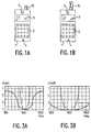
- Figure 1 shows a device according to the invention.
- Figure 2 shows the antenna that is part of the device in a first position.
- Figure 3 shows the antenna part of the device in a second position.
- a device 1 conforming to the invention can be a GSM terminal and must therefore have small dimensions. It includes, as in the usual, a keyboard 2, a screen 3, a microphone 4 and a earpiece 5. It is also provided with an antenna device 10 with a folded position, which is shown in A at the Figure 1, and an unfolded position, which is shown in B on this same figure. The stowed position is used when the device is waiting for a call. This implies that only the receiving part of the device is in operation. In the unfolded position the device is in transmission and, in this case, the antenna adaptation performance must be better.
- FIG. 2 shows in more detail the device antenna 10.
- this antenna is shown in position folded and at B in the unfolded position.
- the reference 20 indicates the antenna excitation point. This point is in contact with a conductive ring 21 which is in contact with a first end of a first propeller 25. The other end of this propeller is in contact with a conductive ring 28.
- These two rings 21 and 28 allow the passage of a strand of radiation 30. This strand of radiation enters a cavity 32 formed in the device 1 when the antenna is in the folded position and emerges outside when the antenna is in the unfolded position.
- a second propeller 35 is placed above this radiating strand 30.
- an insulating element 50 allows a mechanical connection of this propeller 35 with the upper end of said strand 30. This element is rendered visible at A by a notch made in the drawing.
- the lower end of the strand 30 is connected mechanically and electrically to a conductive part circular 55.
- the strand 30 and the propeller 25 participate in the radiation.
- the antenna has an extended bandwidth due to these two coupled resonant systems.
- the two propellers When the antenna is in the folded position, the two propellers are placed in series or in cascade which increases their mechanical height and, therefore, radio efficiency which is related to this height.
- FIG 3 shows the performance, in wave rate stationary (VSWR), obtained by these antennas.
Landscapes
- Engineering & Computer Science (AREA)
- Computer Networks & Wireless Communication (AREA)
- Details Of Aerials (AREA)
- Support Of Aerials (AREA)
Abstract
Description
- une liaison d'excitation pour être raccordé à des circuits d'émission et/ou de réception,
- une première hélice de rayonnement dont une extrémité est reliée à ladite liaison d'excitation,
- un brin de rayonnement pour rayonner et/ou capter de l'énergie issue ou en direction de ladite liaison d'excitation, notamment en position dépliée,
- une deuxième hélice située au voisinage de la seconde extrémité dudit brin.
- un élément isolant pour isoler la seconde extrémité dudit brin de ladite deuxième hélice.
Claims (8)
- Appareil de radiotransmission comportant un dispositif d'antenne dépliable depuis une position repliée vers une position dépliée, dispositif formé par :une liaison d'excitation pour être raccordé à des circuits d'émission et/ou de réception,une première hélice de rayonnement dont une extrémité est reliée à ladite liaison d'excitation,un brin de rayonnement pour rayonner et/ou capter de l'énergie issue ou en direction de ladite liaison d'excitation, notamment en position dépliée,une deuxième hélice située au voisinage d'une extrémité dudit brin,
caractérisé en ce qu'il est formé, en outre, par :un élément isolant pour isoler la seconde extrémité dudit brin de ladite deuxième hélice. - Appareil de radiotransmission selon la revendication 1, caractérisé en ce que ledit brin comporte à son autre extrémité une partie de contact pour être reliée à ladite liaison d'excitation en position dépliée.
- Appareil de radiotransmission selon la revendication 1 ou 2, caractérisé en ce qu'il est prévu une deuxième partie de contact pour connecter en cascade les deux hélices en position repliée.
- Appareil de radiotransmission selon l'une des revendications 1 à 3, caractérisé en ce que ledit élément isolant se place à l'intérieur de ladite première hélice lorsque le dispositif d'antenne est en position repliée.
- Dispositif d'antenne dépliable convenant à un appareil selon l'une des revendications 1 à 4, présentant une position repliée évoluant vers une position dépliée, dispositif formé par :une liaison d'excitation pour être raccordé à des circuits d'émission et/ou de réception,une première hélice de rayonnement dont une extrémité est reliée à ladite liaison d'excitation,un brin de rayonnement pour rayonner et/ou capter de l'énergie issue ou en direction de ladite liaison d'excitation, notamment en position dépliée,une deuxième hélice située au voisinage d'une extrémité dudit brin,
caractérisé en ce qu'il est formé, en outre, par :un élément isolant pour isoler la seconde extrémité dudit brin de ladite deuxième hélice. - Dispositif d'antenne dépliable selon la revendication 5, caractérisé en ce que ledit brin comporte à son autre extrémité une partie de contact pour être reliée audit dispositif d'excitation en position dépliée.
- Dispositif d'antenne dépliable selon la revendication 5 ou 6, caractérisé en ce qu'il est prévu une deuxième partie de contact pour connecter en cascade les deux hélices en position repliée.
- Dispositif d'antenne dépliable selon l'une des revendications 5 à 7, caractérisé en ce que ledit élément isolant se place à l'intérieur de ladite première hélice lorsque le dispositif d'antenne est en position repliée.
Applications Claiming Priority (2)
| Application Number | Priority Date | Filing Date | Title |
|---|---|---|---|
| FR9611667 | 1996-09-25 | ||
| FR9611667 | 1996-09-25 |
Publications (2)
| Publication Number | Publication Date |
|---|---|
| EP0833402A1 true EP0833402A1 (fr) | 1998-04-01 |
| EP0833402B1 EP0833402B1 (fr) | 2004-12-08 |
Family
ID=9496042
Family Applications (1)
| Application Number | Title | Priority Date | Filing Date |
|---|---|---|---|
| EP97202822A Expired - Lifetime EP0833402B1 (fr) | 1996-09-25 | 1997-09-15 | Appareil de radiotransmission comportant un dispositif d'antenne repliable et dispositif d'antenne pour un tel appareil |
Country Status (4)
| Country | Link |
|---|---|
| US (1) | US5900839A (fr) |
| EP (1) | EP0833402B1 (fr) |
| JP (1) | JP3919895B2 (fr) |
| DE (1) | DE69731861T2 (fr) |
Cited By (5)
| Publication number | Priority date | Publication date | Assignee | Title |
|---|---|---|---|---|
| EP0825672A2 (fr) * | 1996-08-22 | 1998-02-25 | Lk-Products Oy | Antenne à double fréquence |
| EP0986132A2 (fr) * | 1998-09-07 | 2000-03-15 | Ace Technology | Antenne hélicoidale pour téléphones portables et méthode pour sa fabrication |
| US6417808B1 (en) | 2000-03-07 | 2002-07-09 | Nec Corporation | Transceiver including antenna apparatus which is compactly accommodated in body of transceiver |
| GB2335312B (en) * | 1998-02-27 | 2002-10-09 | Motorola Inc | An antenna adapted to operate in a plurality of frequency bands |
| US6777117B1 (en) | 1999-03-18 | 2004-08-17 | Matsushita Electric Works, Ltd. | Catalysts for water gas shift reaction, method for removing carbon monoxide in hydrogen gas and electric power-generating system of fuel cell |
Families Citing this family (6)
| Publication number | Priority date | Publication date | Assignee | Title |
|---|---|---|---|---|
| US6047166A (en) * | 1998-03-23 | 2000-04-04 | Lan; Chih Hung | Gain structure of antennae of mobile phones |
| US7226591B2 (en) * | 2000-05-22 | 2007-06-05 | Genentech, Inc. | Interleukin-22 polypeptides, nucleic acids encoding the same and methods for the treatment of pancreatic disorders |
| US6204818B1 (en) * | 2000-02-01 | 2001-03-20 | Auden Technology Mfg. Co., Ltd. | Stretchable antenna for mobile phones |
| US6359592B1 (en) | 2000-11-10 | 2002-03-19 | Motorola, Inc. | Minimum frequency shift telescoping antenna |
| JP3515559B2 (ja) | 2002-01-09 | 2004-04-05 | 日本アンテナ株式会社 | 多周波用アンテナ |
| CN110416730B (zh) * | 2018-04-27 | 2021-08-31 | Oppo广东移动通信有限公司 | 电子设备和电子设备的控制方法 |
Citations (2)
| Publication number | Priority date | Publication date | Assignee | Title |
|---|---|---|---|---|
| EP0644606A1 (fr) * | 1993-09-16 | 1995-03-22 | Fujitsu Limited | Appareil de communication portatif et antenne chargée pour cet appareil |
| WO1995012224A1 (fr) * | 1993-10-29 | 1995-05-04 | Allgon Ab | Ensemble antenne a large bande |
Family Cites Families (2)
| Publication number | Priority date | Publication date | Assignee | Title |
|---|---|---|---|---|
| US5650789A (en) * | 1995-10-10 | 1997-07-22 | Galtronics Ltd. | Retractable antenna system |
| US5764191A (en) * | 1996-10-07 | 1998-06-09 | Sony Corporation | Retractable antenna assembly for a portable radio device |
-
1997
- 1997-09-11 US US08/927,887 patent/US5900839A/en not_active Expired - Lifetime
- 1997-09-15 EP EP97202822A patent/EP0833402B1/fr not_active Expired - Lifetime
- 1997-09-15 DE DE69731861T patent/DE69731861T2/de not_active Expired - Lifetime
- 1997-09-22 JP JP25683897A patent/JP3919895B2/ja not_active Expired - Fee Related
Patent Citations (2)
| Publication number | Priority date | Publication date | Assignee | Title |
|---|---|---|---|---|
| EP0644606A1 (fr) * | 1993-09-16 | 1995-03-22 | Fujitsu Limited | Appareil de communication portatif et antenne chargée pour cet appareil |
| WO1995012224A1 (fr) * | 1993-10-29 | 1995-05-04 | Allgon Ab | Ensemble antenne a large bande |
Cited By (7)
| Publication number | Priority date | Publication date | Assignee | Title |
|---|---|---|---|---|
| EP0825672A2 (fr) * | 1996-08-22 | 1998-02-25 | Lk-Products Oy | Antenne à double fréquence |
| EP0825672A3 (fr) * | 1996-08-22 | 2000-03-22 | Lk-Products Oy | Antenne à double fréquence |
| GB2335312B (en) * | 1998-02-27 | 2002-10-09 | Motorola Inc | An antenna adapted to operate in a plurality of frequency bands |
| EP0986132A2 (fr) * | 1998-09-07 | 2000-03-15 | Ace Technology | Antenne hélicoidale pour téléphones portables et méthode pour sa fabrication |
| EP0986132A3 (fr) * | 1998-09-07 | 2001-10-17 | Ace Technology | Antenne hélicoidale pour téléphones portables et méthode pour sa fabrication |
| US6777117B1 (en) | 1999-03-18 | 2004-08-17 | Matsushita Electric Works, Ltd. | Catalysts for water gas shift reaction, method for removing carbon monoxide in hydrogen gas and electric power-generating system of fuel cell |
| US6417808B1 (en) | 2000-03-07 | 2002-07-09 | Nec Corporation | Transceiver including antenna apparatus which is compactly accommodated in body of transceiver |
Also Published As
| Publication number | Publication date |
|---|---|
| JPH10112606A (ja) | 1998-04-28 |
| DE69731861T2 (de) | 2006-03-02 |
| DE69731861D1 (de) | 2005-01-13 |
| US5900839A (en) | 1999-05-04 |
| EP0833402B1 (fr) | 2004-12-08 |
| JP3919895B2 (ja) | 2007-05-30 |
Similar Documents
| Publication | Publication Date | Title |
|---|---|---|
| EP1589608A1 (fr) | Antenne compacte RF | |
| EP0833402A1 (fr) | "Appareil de radiotransmission comportant un dispositif d'antenne repliable et dispositif d'antenne pour un tel appareil" | |
| EP0995234A1 (fr) | Antenne a plaque | |
| FR2812766A1 (fr) | Antenne a surface(s) rayonnante(s) plane(s) et telephone portable comportant une telle antenne | |
| EP1407512A1 (fr) | Antenne | |
| FR2578105A1 (fr) | Antenne plane a micro-ondes | |
| FR2760919A1 (fr) | Systeme de communication par satellite mobile | |
| FR2730094A1 (fr) | Antenne radio | |
| FR2760132A1 (fr) | Antenne alimentee par bobines cote a cote pour un poste radio portable | |
| EP3352301A1 (fr) | Antenne pour dispositif mobile de communication | |
| CA2489776C (fr) | Antenne a brins a polarisation circulaire | |
| FR2709604A1 (fr) | Antenne pour appareil radio portatif. | |
| FR2754942A1 (fr) | Systeme antennaire pour poste radiotelephone portatif | |
| EP1577975B1 (fr) | Téléphone en deux parties comportant une antenne à surfaces planes rayonnantes | |
| EP3641058B1 (fr) | Antenne multibandes commutée et dispositif radiofréquence comprenant une telle antenne | |
| EP1538696A1 (fr) | Téléphone mobile bi-bande à diagramme de rayonnement omnidirectionnel | |
| EP0082053B1 (fr) | Ensemble rayonnant à deux antennes superposées travaillant dans une même gamme de fréquences | |
| FR2591807A1 (fr) | Antenne dielectrique | |
| EP1249889B1 (fr) | Filtre hyperfréquence à résonateur diélectrique | |
| CA2294578A1 (fr) | Antenne a efficacite de liaison amelioree | |
| WO2002037606A1 (fr) | Antenne multibande | |
| FR2772991A1 (fr) | Antenne fixe g.s.m. | |
| EP2462701B1 (fr) | Circuit de commutation pour des signaux large bande | |
| FR2867904A1 (fr) | Systeme de reception et de decodage d'ondes electromagnetiques muni d'une antenne compacte | |
| EP1956682B1 (fr) | Antenne monopôle à commutation |
Legal Events
| Date | Code | Title | Description |
|---|---|---|---|
| PUAI | Public reference made under article 153(3) epc to a published international application that has entered the european phase |
Free format text: ORIGINAL CODE: 0009012 |
|
| AK | Designated contracting states |
Kind code of ref document: A1 Designated state(s): DE FR GB |
|
| AX | Request for extension of the european patent |
Free format text: AL;LT;LV;RO;SI |
|
| RAP3 | Party data changed (applicant data changed or rights of an application transferred) |
Owner name: KONINKLIJKE PHILIPS ELECTRONICS N.V. |
|
| 17P | Request for examination filed |
Effective date: 19981001 |
|
| AKX | Designation fees paid |
Free format text: DE FR GB |
|
| RBV | Designated contracting states (corrected) |
Designated state(s): DE FR GB |
|
| 17Q | First examination report despatched |
Effective date: 20011227 |
|
| GRAP | Despatch of communication of intention to grant a patent |
Free format text: ORIGINAL CODE: EPIDOSNIGR1 |
|
| GRAS | Grant fee paid |
Free format text: ORIGINAL CODE: EPIDOSNIGR3 |
|
| GRAA | (expected) grant |
Free format text: ORIGINAL CODE: 0009210 |
|
| AK | Designated contracting states |
Kind code of ref document: B1 Designated state(s): DE FR GB |
|
| REG | Reference to a national code |
Ref country code: GB Ref legal event code: FG4D Free format text: NOT ENGLISH |
|
| REF | Corresponds to: |
Ref document number: 69731861 Country of ref document: DE Date of ref document: 20050113 Kind code of ref document: P |
|
| GBT | Gb: translation of ep patent filed (gb section 77(6)(a)/1977) |
Effective date: 20050321 |
|
| PLBE | No opposition filed within time limit |
Free format text: ORIGINAL CODE: 0009261 |
|
| STAA | Information on the status of an ep patent application or granted ep patent |
Free format text: STATUS: NO OPPOSITION FILED WITHIN TIME LIMIT |
|
| 26N | No opposition filed |
Effective date: 20050909 |
|
| REG | Reference to a national code |
Ref country code: FR Ref legal event code: TP |
|
| PGFP | Annual fee paid to national office [announced via postgrant information from national office to epo] |
Ref country code: DE Payment date: 20090910 Year of fee payment: 13 |
|
| PGFP | Annual fee paid to national office [announced via postgrant information from national office to epo] |
Ref country code: FR Payment date: 20091012 Year of fee payment: 13 |
|
| REG | Reference to a national code |
Ref country code: FR Ref legal event code: ST Effective date: 20110531 |
|
| REG | Reference to a national code |
Ref country code: DE Ref legal event code: R119 Ref document number: 69731861 Country of ref document: DE Effective date: 20110401 |
|
| PG25 | Lapsed in a contracting state [announced via postgrant information from national office to epo] |
Ref country code: FR Free format text: LAPSE BECAUSE OF NON-PAYMENT OF DUE FEES Effective date: 20100930 Ref country code: DE Free format text: LAPSE BECAUSE OF NON-PAYMENT OF DUE FEES Effective date: 20110401 |
|
| PGFP | Annual fee paid to national office [announced via postgrant information from national office to epo] |
Ref country code: GB Payment date: 20120829 Year of fee payment: 16 |
|
| GBPC | Gb: european patent ceased through non-payment of renewal fee |
Effective date: 20130915 |
|
| PG25 | Lapsed in a contracting state [announced via postgrant information from national office to epo] |
Ref country code: GB Free format text: LAPSE BECAUSE OF NON-PAYMENT OF DUE FEES Effective date: 20130915 |