EP0833180A2 - Catadioptric objective for microlithographic reduction - Google Patents
Catadioptric objective for microlithographic reduction Download PDFInfo
- Publication number
- EP0833180A2 EP0833180A2 EP97115480A EP97115480A EP0833180A2 EP 0833180 A2 EP0833180 A2 EP 0833180A2 EP 97115480 A EP97115480 A EP 97115480A EP 97115480 A EP97115480 A EP 97115480A EP 0833180 A2 EP0833180 A2 EP 0833180A2
- Authority
- EP
- European Patent Office
- Prior art keywords
- objective according
- mirrors
- lenses
- reduction objective
- reduction
- Prior art date
- Legal status (The legal status is an assumption and is not a legal conclusion. Google has not performed a legal analysis and makes no representation as to the accuracy of the status listed.)
- Withdrawn
Links
Images
Classifications
-
- G—PHYSICS
- G02—OPTICS
- G02B—OPTICAL ELEMENTS, SYSTEMS OR APPARATUS
- G02B17/00—Systems with reflecting surfaces, with or without refracting elements
- G02B17/08—Catadioptric systems
- G02B17/0892—Catadioptric systems specially adapted for the UV
-
- G—PHYSICS
- G02—OPTICS
- G02B—OPTICAL ELEMENTS, SYSTEMS OR APPARATUS
- G02B17/00—Systems with reflecting surfaces, with or without refracting elements
- G02B17/08—Catadioptric systems
- G02B17/0804—Catadioptric systems using two curved mirrors
- G02B17/0808—Catadioptric systems using two curved mirrors on-axis systems with at least one of the mirrors having a central aperture
-
- G—PHYSICS
- G03—PHOTOGRAPHY; CINEMATOGRAPHY; ANALOGOUS TECHNIQUES USING WAVES OTHER THAN OPTICAL WAVES; ELECTROGRAPHY; HOLOGRAPHY
- G03F—PHOTOMECHANICAL PRODUCTION OF TEXTURED OR PATTERNED SURFACES, e.g. FOR PRINTING, FOR PROCESSING OF SEMICONDUCTOR DEVICES; MATERIALS THEREFOR; ORIGINALS THEREFOR; APPARATUS SPECIALLY ADAPTED THEREFOR
- G03F7/00—Photomechanical, e.g. photolithographic, production of textured or patterned surfaces, e.g. printing surfaces; Materials therefor, e.g. comprising photoresists; Apparatus specially adapted therefor
- G03F7/70—Microphotolithographic exposure; Apparatus therefor
- G03F7/70216—Mask projection systems
- G03F7/70225—Optical aspects of catadioptric systems, i.e. comprising reflective and refractive elements
-
- G—PHYSICS
- G03—PHOTOGRAPHY; CINEMATOGRAPHY; ANALOGOUS TECHNIQUES USING WAVES OTHER THAN OPTICAL WAVES; ELECTROGRAPHY; HOLOGRAPHY
- G03F—PHOTOMECHANICAL PRODUCTION OF TEXTURED OR PATTERNED SURFACES, e.g. FOR PRINTING, FOR PROCESSING OF SEMICONDUCTOR DEVICES; MATERIALS THEREFOR; ORIGINALS THEREFOR; APPARATUS SPECIALLY ADAPTED THEREFOR
- G03F7/00—Photomechanical, e.g. photolithographic, production of textured or patterned surfaces, e.g. printing surfaces; Materials therefor, e.g. comprising photoresists; Apparatus specially adapted therefor
- G03F7/70—Microphotolithographic exposure; Apparatus therefor
- G03F7/70216—Mask projection systems
- G03F7/70275—Multiple projection paths, e.g. array of projection systems, microlens projection systems or tandem projection systems
Landscapes
- Physics & Mathematics (AREA)
- General Physics & Mathematics (AREA)
- Optics & Photonics (AREA)
- Lenses (AREA)
Abstract
Description
Die Erfindung betrifft ein katadioptrisches Mikrolithographie-Reduktionsobjektiv mit zwei einander zugewandten Konkavspiegeln mit achssymmetrischem Aufbau und zentraler Abschattung.The invention relates to a catadioptric microlithography reduction lens with two concave mirrors facing each other with axisymmetric structure and central shading.
Katadioptrische Reduktionsobjektive für die DUV-Mikrolithographie sind bekannt: In der Ausführung nach der Patentanmeldung DE 196 16 922.4 und den darin angegebenen Zitaten ist ein diagonal stehender polarisierender Strahlteiler und eine Viertelwellenlängenplatte erforderlich. Beide sind im DUV-Wellenlängenbereich ein herstelltechnisches Problem. Zudem ist eine Umlenkung der optischen Achse um ca. 90° unabdingbar, so daß regelmäßig eine zweite Umlenkung vorgesehen wird, um die Parallelität von Reticle und Wafer zu erhalten.Catadioptric reduction lenses for DUV microlithography are known: In the execution after the patent application DE 196 16 922.4 and the quotations given therein a diagonally standing polarizing beam splitter and one Quarter wavelength plate required. Both are in the DUV wavelength range a manufacturing problem. In addition is a deflection of the optical axis by approx. 90 ° is indispensable, so that a second diversion is regularly provided to the Maintain parallelism of reticle and wafer.
Andere katadioptrische Systeme sind asymmetrisch aufgebaut,
z.B. vom Dyson-Typ oder nach EP 0 581 585 und darin angegebenen
Zitaten.Other catadioptric systems are asymmetrical,
e.g. of the Dyson type or according to
Aus der US 5,488,229 ist ein gattungsgemäßes katadioptrisches Mikrolithographie-Reduktionsobjektiv bekannt, das achssymmetrisch aufgebaut ist und zwei einander zugekehrte Konkavspiegel aufweist. Prinzipiell ist eine zentrale Abschattung gegeben, die jedoch in Anbetracht der immer größeren Bedeutung von Ringaperturbeleuchtungen kein Problem darstellt.From US 5,488,229 is a generic catadioptric Microlithography reduction lens known, the axisymmetric and two concave mirrors facing each other having. In principle, there is central shading given, however, given the increasing importance of ring aperture lights is not a problem.
Beide Konkavspiegel sind als Manginspiegel ausgeführt, der zweite wirkt in seinem mittigen Bereich als Linse. Nachfolgend sind nur noch die Iris-Blende und der Wafer angeordnet. Das Beispiel kommt bei β = 0,1, NA = 0,6, Lambda = 193 nm mit fünf Linsen und zwei Mangin-Spiegeln aus. Allerdings ist zur Bildfeldgröße und zur Größe der mittigen Abschattung nichts ausgesagt. Bei Bildfeldgrößen, wie sie mit der Erfindung erreicht werden, wären Manginspiegel mit Durchmessern bis zu einem Meter erforderlich. Es ist nicht absehbar, daß Quarzglas oder gar ein anderer Linsenwerkstoff in diesen Abmessungen in der für die DUV-Mikrolithographie unverzichtbaren Qualität bereitgestellt werden kann.Both concave mirrors are designed as manganese mirrors the second acts as a lens in its central area. Below only the iris diaphragm and the wafer are arranged. The Example comes at β = 0.1, NA = 0.6, Lambda = 193 nm with five Lentils and two Mangin mirrors. However, the image field size and nothing about the size of the central shading testified. With image field sizes as they are with the invention would be reached, manganese levels with diameters up to one meter required. It is not foreseeable that quartz glass or even another lens material in these dimensions in the quality indispensable for DUV microlithography can be provided.
US 5,031,976 gibt einen ähnlichen Aufbau an. Der zweite Spiegel ist jedoch plan und zwischen den Spiegeln ist eine separate dicke Linse vorgesehen.US 5,031,976 gives a similar structure. The second mirror is flat, however, and there is a separate one between the mirrors thick lens provided.
Aufgabe der Erfindung ist die Bereitstellung eines gattungsgemäßen Reduktionsobjektivs mit einem Bildfeld, dessen Größe den Produktionsanforderungen von Wafer Steppern entspricht, und mit einer geeigneten Fehlerkorrektur. Dabei soll eine produktionstechnisch gangbare Konstruktion angegeben werden, die besonders große und dicke Linsen vermeidet.The object of the invention is to provide a generic Reduction lens with an image field, its size meets the production requirements of wafer steppers, and with a suitable error correction. One should production feasible construction are specified, which avoids particularly large and thick lenses.
Die Lösung findet sich mit einem Reduktionsobjektiv nach
Anspruch 1, dessen Kennzeichen es ist, daß den Spiegeln auf dem
Lichtweg zum Bild Linsen nachgeordnet sind. Hier ist das Lichtbündel
wieder auf einen Durchmesser reduziert, der erheblich
kleiner als die Spiegeldurchmesser ist, so daß Korrekturlinsen
mit mäßigen Durchmessern eingesetzt werden können.The solution can be found with a
Vorteilhaft ist es gemäß Anspruch 2, wenn das objektseitige
Linsensystem in den Spiegelzwischenraum im Bereich der
zentralen Abschattung hineinragt. Damit werden die Farbfehler
positiv beeinflußt.It is advantageous according to
Ist der Lichtweg zwischen den Spiegeln, also im Bereich des
größten Lichtbündeldurchmessers, frei von Linsen gemäß Anspruch
3, so ist insbesondere das Ziel, kleine Linsen zu benutzen,
erreicht.Is the light path between the mirrors, i.e. in the area of the
largest light beam diameter, free of lenses according to
Mit einem Zwischenbild nach den Spiegeln gemäß Anspruch 4,
ergeben sich im Raum zwischen Zwischenbild und Bild zu den
Spiegeln konjugierte Flächen, in deren Nähe optimal Elemente
zur Korrektur der von den Spiegeln verursachten Bildfehler
angeordnet werden können. Geeignet hierzu ist ein Meniskenpaar. With an intermediate image according to the mirrors according to
Die Ausbildung nach Anspruch 5 betrifft ein Korrekturelement,
nämlich eine zwischen zwei Linsen eingeschlossene konvexe Luftlinse,
mit der gute Astigmatismuskorrektion erreicht werden
kann.The embodiment according to
Die Ansprüche 6-9 geben die erreichte vorteilhafte Qualität mit großem Bildfeld bei großer numerischer Apertur, geringer Bildfeldkrümmung und ausreichender chromatischer Bandbreite an.Claims 6-9 indicate the advantageous quality achieved large image field with large numerical aperture, low image field curvature and sufficient chromatic bandwidth.
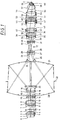
Näher erläutert wird die Erfindung anhand der Zeichnung.
Figur 1- zeigt den Linsenschnitt eines bevorzugten Ausführungsbeispiels.
- Figure 1
- shows the lens section of a preferred embodiment.
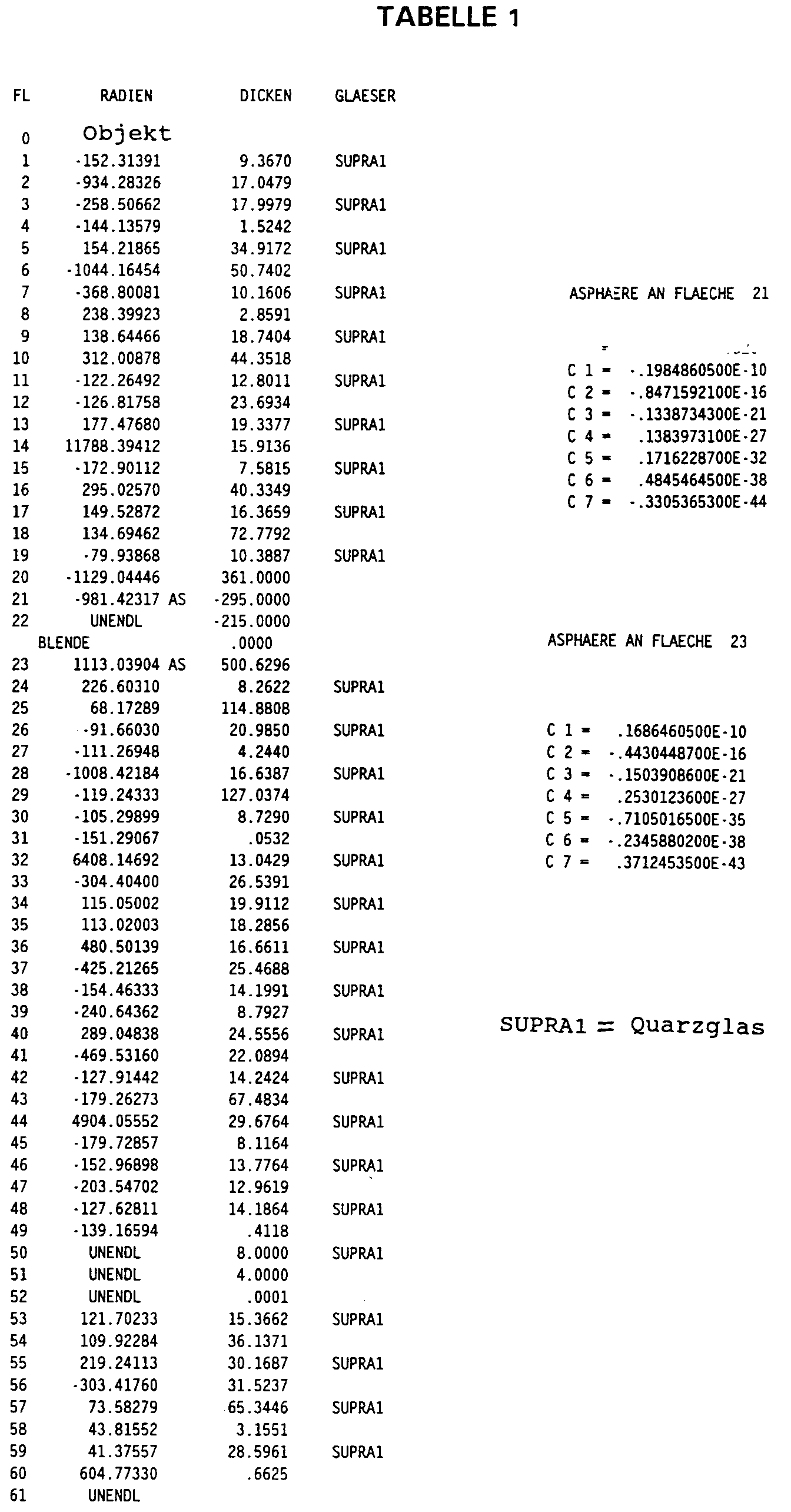
Der Linsenschnitt der Figur 1 mit den Daten der Tabelle 1 gibt
das bevorzugte Ausführungsbeispiel an. Hier sind insgesamt 27
Linsen und zwei Spiegel 21, 23, sowie eine Planplatte 50/51
vorgesehen. Bei einem Bildfelddurchmesser von 27 mm beträgt der
Durchmesser der größten Linse 19/20 ca. 173 mm, der Durchmesser
des größten Spiegels 23 beträgt ca. 707 mm. Die zentrale
Abschattung beträgt ca. 35 % des Spiegeldurchmessers.
Ausgelegt ist das Objektiv für die Wellenlänge 193,38 nm. die
bildseitige numerische Apertur ist 0,70.The lens section of Figure 1 with the data in Table 1 gives
the preferred embodiment. Here are a total of 27
Lenses and two
Eine Zwischenbildebene Z ist zwischen den Flächen 29 und 30
realisiert und an der dementsprechenden zusätzlichen Pupille P
sind die Menisken 46, 47; 48, 49 und 53, 54 vorgesehen, welche
von den Spiegeln 21, 23 erzeugte Bildfehler, insbesondere
außeraxiale, hier optimal korrigieren können.An intermediate image plane Z is between the
Zwischen den Menisken, unmittelbar im Bereich der Pupille p,
ist eine Planplatte 50, 51 vorgesehen. In der Herstellung
dieser Objektive kann diese Planplatte 50, 51 dazu benutzt
werden, Restfehler des Objektiv-Exemplars durch kleine Formkorrekturen,
welche zum Beispiel durch Ionenstrahlätzen erzeugt
werden können, zu korrigieren. Between the menisci, directly in the area of the pupil p,
a
Die objektseitige Linsengruppe 1-20 ist vom Typ eines Weitwinkel-Retrofokusobjektivs,
dazu gespiegelt ist auch die
Linsengruppe 25-33 vor dem Zwischenbild von diesem Typ. Die bei
beiden spiegelseitigen zerstreuenden Menisken 19, 20 und 24, 25
machen die Lichtbündel spiegelseitig stark divergent und
ergeben so die geringe zentrale Abschattung. Die beiden Linsengruppen
1-20 und 24-33 tauchen so in die Spiegelanordnung 21,
23 ein. Wichtig ist auch die Funktion der Menisken 19, 20 und
24, 25, einen großen Farblängsfehler vorzuhalten. Dieser wird
von den gesamten restlichen Linsen wieder kompensiert.The lens group 1-20 on the object side is of the type of a wide-angle retrofocus lens,
this is also mirrored
Lens group 25-33 in front of the intermediate image of this type. The at
two
Die stark konvexe Fläche 57 in Verbindung mit der weitgehenden
Glasfüllung des Raums bis zum Objekt 60 ist für die vorliegende
Objektivklasse signifikant und ähnlich bei Mikroskopobjektiven
üblich.The strongly
Alle Linsen sind sphärisch und aus Quarzglas gefertigt. Für den Betrieb mit niedrigeren Wellenlängen (z.B. 157 nm) können auch andere Werkstoffe (Kalziumfluorid) vorgesehen werden.All lenses are spherical and made of quartz glass. For the Operation with lower wavelengths (e.g. 157 nm) can also other materials (calcium fluoride) can be provided.
Die Spiegel sind asphärisch nach der bekannten Potenzreihenentwicklung
Die Herstellung derartiger asphärischer Spiegel im Durchmesserbereich
um einen halben bis zu einem Meter ist aus dem Bereich
der astronomischen Instrumente bekannt. Zur Serienfertigung
können auch Abformtechniken, z.B. die Galvanoplastik,
herangezogen werden. Die Fertigungsgenauigkeit kann beschränkt
bleiben, da konjugierte Korrekturflächen auf der obenerwähnten
Planplatte 50/51 oder auf einer der benachbarten Meniskenflächen
52 usw. zur Verfügung stehen. The manufacture of such aspherical mirrors in the diameter range
is out of the range by a half to a meter
of astronomical instruments. For series production
impression techniques, e.g. galvanoplastic,
be used. The manufacturing accuracy can be limited
remain because conjugate correction surfaces on the above
Auch ist es möglich, elastische Spiegel vorzusehen. Einmal
können diese in Abwandlung des bekannten Richtkittens mit
Aktuatoren in einer Montagephase einjustiert und dann an einem
starren Träger fixiert werden. Andererseits können diese auch
im Betrieb on-line mit z.B. piezoelektrischen Aktuatoren in
optimale Form geregelt werden, um z.B. thermische Linseneffekte
auszugleichen.
Claims (11)
Applications Claiming Priority (2)
| Application Number | Priority Date | Filing Date | Title |
|---|---|---|---|
| DE19639586 | 1996-09-26 | ||
| DE1996139586 DE19639586A1 (en) | 1996-09-26 | 1996-09-26 | Catadioptric microlithography reduction lens |
Publications (2)
| Publication Number | Publication Date |
|---|---|
| EP0833180A2 true EP0833180A2 (en) | 1998-04-01 |
| EP0833180A3 EP0833180A3 (en) | 1998-07-22 |
Family
ID=7806978
Family Applications (1)
| Application Number | Title | Priority Date | Filing Date |
|---|---|---|---|
| EP97115480A Withdrawn EP0833180A3 (en) | 1996-09-26 | 1997-09-06 | Catadioptric objective for microlithographic reduction |
Country Status (3)
| Country | Link |
|---|---|
| EP (1) | EP0833180A3 (en) |
| JP (1) | JPH10104513A (en) |
| DE (1) | DE19639586A1 (en) |
Cited By (5)
| Publication number | Priority date | Publication date | Assignee | Title |
|---|---|---|---|---|
| EP0989434A2 (en) * | 1998-07-29 | 2000-03-29 | Carl Zeiss | Catadioptric optical system and exposure apparatus having the same |
| EP1260845A2 (en) * | 2001-05-22 | 2002-11-27 | Carl Zeiss Semiconductor Manufacturing Technologies Ag | Catadioptric reduction lens |
| EP1336887A1 (en) * | 2000-10-23 | 2003-08-20 | Nikon Corporation | Catadioptric system and exposure device having this system |
| US8064041B2 (en) | 2004-06-10 | 2011-11-22 | Carl Zeiss Smt Gmbh | Projection objective for a microlithographic projection exposure apparatus |
| US8174676B2 (en) | 2005-07-01 | 2012-05-08 | Carl Zeiss Smt Gmbh | Method for correcting a lithography projection objective, and such a projection objective |
Families Citing this family (11)
| Publication number | Priority date | Publication date | Assignee | Title |
|---|---|---|---|---|
| JP4117856B2 (en) * | 1997-12-12 | 2008-07-16 | 株式会社小松製作所 | Narrow-band oscillation excimer laser and fluoride prism |
| WO1999060616A1 (en) | 1998-05-15 | 1999-11-25 | Nikon Corporation | Exposure method and apparatus |
| DE19939088A1 (en) | 1998-08-18 | 2000-02-24 | Nikon Corp | Exposure apparatus, especially in photolithography for producing e.g. semiconductor devices, chips and thin film magnetic heads, has a projection system with refractive optical components of different crystalline fluorides |
| JP4717974B2 (en) | 1999-07-13 | 2011-07-06 | 株式会社ニコン | Catadioptric optical system and projection exposure apparatus provided with the optical system |
| US6600608B1 (en) * | 1999-11-05 | 2003-07-29 | Carl-Zeiss-Stiftung | Catadioptric objective comprising two intermediate images |
| TW538256B (en) | 2000-01-14 | 2003-06-21 | Zeiss Stiftung | Microlithographic reduction projection catadioptric objective |
| JP2004514943A (en) | 2000-11-28 | 2004-05-20 | カール・ツアイス・エスエムテイ・アーゲー | Catadioptric projection system for 157nm lithography |
| US7085075B2 (en) * | 2003-08-12 | 2006-08-01 | Carl Zeiss Smt Ag | Projection objectives including a plurality of mirrors with lenses ahead of mirror M3 |
| US7023524B2 (en) * | 2003-12-18 | 2006-04-04 | Asml Netherlands B.V. | Lithographic apparatus and device manufacturing method |
| JP5495555B2 (en) * | 2005-03-31 | 2014-05-21 | ケーエルエー−テンカー コーポレイション | Compact and ultra high NA catadioptric objective lens using aspheric surfaces |
| JP5836686B2 (en) * | 2011-07-28 | 2015-12-24 | キヤノン株式会社 | Catadioptric optical system and imaging apparatus having the same |
Citations (5)
| Publication number | Priority date | Publication date | Assignee | Title |
|---|---|---|---|---|
| US3244073A (en) * | 1961-09-19 | 1966-04-05 | Optische Ind De Oude Delft Nv | Centered optical mirror system having finite conjegates |
| EP0267766A2 (en) * | 1986-11-10 | 1988-05-18 | Compact Spindle Bearing Corporation | Catoptric reduction imaging systems |
| EP0396128A2 (en) * | 1989-05-03 | 1990-11-07 | Hughes Aircraft Company | Catadioptric projector, catadioptric projection system and process |
| EP0581585A1 (en) * | 1992-07-29 | 1994-02-02 | Nikon Corporation | Catadioptric reduction projection optical system |
| DE29516768U1 (en) * | 1995-10-24 | 1996-02-01 | Lindener Werner | Dipped mirror lens |
Family Cites Families (3)
| Publication number | Priority date | Publication date | Assignee | Title |
|---|---|---|---|---|
| US5031976A (en) * | 1990-09-24 | 1991-07-16 | Kla Instruments, Corporation | Catadioptric imaging system |
| US5557469A (en) * | 1994-10-28 | 1996-09-17 | Ultratech Stepper, Inc. | Beamsplitter in single fold optical system and optical variable magnification method and system |
| US5717518A (en) * | 1996-07-22 | 1998-02-10 | Kla Instruments Corporation | Broad spectrum ultraviolet catadioptric imaging system |
-
1996
- 1996-09-26 DE DE1996139586 patent/DE19639586A1/en not_active Withdrawn
-
1997
- 1997-09-06 EP EP97115480A patent/EP0833180A3/en not_active Withdrawn
- 1997-09-26 JP JP9261501A patent/JPH10104513A/en active Pending
Patent Citations (5)
| Publication number | Priority date | Publication date | Assignee | Title |
|---|---|---|---|---|
| US3244073A (en) * | 1961-09-19 | 1966-04-05 | Optische Ind De Oude Delft Nv | Centered optical mirror system having finite conjegates |
| EP0267766A2 (en) * | 1986-11-10 | 1988-05-18 | Compact Spindle Bearing Corporation | Catoptric reduction imaging systems |
| EP0396128A2 (en) * | 1989-05-03 | 1990-11-07 | Hughes Aircraft Company | Catadioptric projector, catadioptric projection system and process |
| EP0581585A1 (en) * | 1992-07-29 | 1994-02-02 | Nikon Corporation | Catadioptric reduction projection optical system |
| DE29516768U1 (en) * | 1995-10-24 | 1996-02-01 | Lindener Werner | Dipped mirror lens |
Cited By (15)
| Publication number | Priority date | Publication date | Assignee | Title |
|---|---|---|---|---|
| EP0989434A2 (en) * | 1998-07-29 | 2000-03-29 | Carl Zeiss | Catadioptric optical system and exposure apparatus having the same |
| EP0989434A3 (en) * | 1998-07-29 | 2001-10-17 | Carl Zeiss | Catadioptric optical system and exposure apparatus having the same |
| EP1336887A4 (en) * | 2000-10-23 | 2008-07-09 | Nikon Corp | Catadioptric system and exposure device having this system |
| EP1336887A1 (en) * | 2000-10-23 | 2003-08-20 | Nikon Corporation | Catadioptric system and exposure device having this system |
| US7006304B2 (en) | 2001-05-22 | 2006-02-28 | Carl Zeiss Smt Ag | Catadioptric reduction lens |
| US6717746B2 (en) | 2001-05-22 | 2004-04-06 | Carl Zeiss Semiconductor Manufacturing Technologies Ag | Catadioptric reduction lens |
| EP1260845A3 (en) * | 2001-05-22 | 2004-01-02 | Carl Zeiss Semiconductor Manufacturing Technologies Ag | Catadioptric reduction lens |
| EP1260845A2 (en) * | 2001-05-22 | 2002-11-27 | Carl Zeiss Semiconductor Manufacturing Technologies Ag | Catadioptric reduction lens |
| US8064041B2 (en) | 2004-06-10 | 2011-11-22 | Carl Zeiss Smt Gmbh | Projection objective for a microlithographic projection exposure apparatus |
| US8902407B2 (en) | 2004-06-10 | 2014-12-02 | Carl Zeiss Smt Gmbh | Projection objective for a microlithographic projection exposure apparatus |
| US9280058B2 (en) | 2004-06-10 | 2016-03-08 | Carl Zeiss Smt Gmbh | Projection objective for a microlithographic projection exposure apparatus |
| US9588445B2 (en) | 2004-06-10 | 2017-03-07 | Carl Zeiss Smt Gmbh | Projection objective for a microlithographic projection exposure apparatus |
| US9977338B2 (en) | 2004-06-10 | 2018-05-22 | Carl Zeiss Smt Gmbh | Projection objective for a microlithographic projection exposure apparatus |
| US8174676B2 (en) | 2005-07-01 | 2012-05-08 | Carl Zeiss Smt Gmbh | Method for correcting a lithography projection objective, and such a projection objective |
| US8659744B2 (en) | 2005-07-01 | 2014-02-25 | Carl Zeiss Smt Gmbh | Method for correcting a lithography projection objective, and such a projection objective |
Also Published As
| Publication number | Publication date |
|---|---|
| DE19639586A1 (en) | 1998-04-02 |
| EP0833180A3 (en) | 1998-07-22 |
| JPH10104513A (en) | 1998-04-24 |
Similar Documents
| Publication | Publication Date | Title |
|---|---|---|
| DE69933973T2 (en) | CATADIOPRIC OPTICAL SYSTEM AND EQUIPPED EXPOSURE DEVICE | |
| EP1480082B1 (en) | Ringfield four mirror system with convex primary mirror for EUV lithography | |
| DE69531153T3 (en) | Optical projection system with exposure device | |
| DE60028245T2 (en) | PROJECTION OBJECTIVE FOR MICROLITHOGRAPHIC REDUCTION | |
| EP0833180A2 (en) | Catadioptric objective for microlithographic reduction | |
| EP0687956B1 (en) | Illumination device | |
| EP0710369A1 (en) | Very wide aperture catadioptric reducing object lens for microlithography | |
| EP1855160B1 (en) | Projection exposure device, projection exposure method and use of a projection lens | |
| DE10210899A1 (en) | Refractive projection lens for immersion lithography | |
| DE69824658T2 (en) | Optical system for projection | |
| EP1097404A1 (en) | Projection lens for microlithography | |
| DE10127227A1 (en) | Catadioptric reduction lens | |
| EP0937999A1 (en) | Optical system with polarisation compensator | |
| DE10139177A1 (en) | Objective with pupil obscuration | |
| EP1122608A2 (en) | Projection exposure system with reflective reticle | |
| DE102008043162A1 (en) | Imaging optics and projection exposure system for microlithography with such an imaging optics | |
| DE19548805A1 (en) | REMA lens for microlithography projection exposure systems | |
| DE3439297C2 (en) | Mirror lens lens | |
| EP1102100A2 (en) | Catadioptric objective with beamsplitter | |
| DE10316428A1 (en) | Catadioptric reduction lens | |
| EP1235112B1 (en) | Objective subsystem for illumination system | |
| EP1227354A2 (en) | Catadioptric reduction objective | |
| DE102022200400A1 (en) | CONNECTION OF COMPONENTS OF AN OPTICAL DEVICE | |
| WO2008043433A1 (en) | Compact 3-mirror objective | |
| DE10020592A1 (en) | Catadioptric lens with physical beam splitter |
Legal Events
| Date | Code | Title | Description |
|---|---|---|---|
| PUAI | Public reference made under article 153(3) epc to a published international application that has entered the european phase |
Free format text: ORIGINAL CODE: 0009012 |
|
| AK | Designated contracting states |
Kind code of ref document: A2 Designated state(s): DE FR GB IT NL |
|
| AX | Request for extension of the european patent |
Free format text: AL;LT;LV;RO;SI |
|
| PUAL | Search report despatched |
Free format text: ORIGINAL CODE: 0009013 |
|
| AK | Designated contracting states |
Kind code of ref document: A3 Designated state(s): AT BE CH DE DK ES FI FR GB GR IE IT LI LU MC NL PT SE |
|
| AX | Request for extension of the european patent |
Free format text: AL;LT;LV;RO;SI |
|
| 17P | Request for examination filed |
Effective date: 19981222 |
|
| AKX | Designation fees paid |
Free format text: DE FR GB IT NL |
|
| RBV | Designated contracting states (corrected) |
Designated state(s): DE FR GB IT NL |
|
| 17Q | First examination report despatched |
Effective date: 20020607 |
|
| GRAP | Despatch of communication of intention to grant a patent |
Free format text: ORIGINAL CODE: EPIDOSNIGR1 |
|
| RAP1 | Party data changed (applicant data changed or rights of an application transferred) |
Owner name: CARL-ZEISS-STIFTUNG TRADING AS CARL ZEISS Owner name: CARL ZEISS |
|
| STAA | Information on the status of an ep patent application or granted ep patent |
Free format text: STATUS: THE APPLICATION IS DEEMED TO BE WITHDRAWN |
|
| 18D | Application deemed to be withdrawn |
Effective date: 20040727 |