EP0832834B1 - Gripper Seat - Google Patents
Gripper Seat Download PDFInfo
- Publication number
- EP0832834B1 EP0832834B1 EP97114681A EP97114681A EP0832834B1 EP 0832834 B1 EP0832834 B1 EP 0832834B1 EP 97114681 A EP97114681 A EP 97114681A EP 97114681 A EP97114681 A EP 97114681A EP 0832834 B1 EP0832834 B1 EP 0832834B1
- Authority
- EP
- European Patent Office
- Prior art keywords
- gripper
- seat
- gripper seat
- sheet material
- body portion
- Prior art date
- Legal status (The legal status is an assumption and is not a legal conclusion. Google has not performed a legal analysis and makes no representation as to the accuracy of the status listed.)
- Expired - Lifetime
Links
- 239000000463 material Substances 0.000 claims description 22
- 239000012858 resilient material Substances 0.000 claims description 2
- 230000000903 blocking effect Effects 0.000 claims 1
- 235000019589 hardness Nutrition 0.000 description 3
- 238000003780 insertion Methods 0.000 description 3
- 230000037431 insertion Effects 0.000 description 3
- JOYRKODLDBILNP-UHFFFAOYSA-N Ethyl urethane Chemical compound CCOC(N)=O JOYRKODLDBILNP-UHFFFAOYSA-N 0.000 description 1
- 238000000034 method Methods 0.000 description 1
- 238000012986 modification Methods 0.000 description 1
- 230000004048 modification Effects 0.000 description 1
Images

Classifications
-
- B—PERFORMING OPERATIONS; TRANSPORTING
- B65—CONVEYING; PACKING; STORING; HANDLING THIN OR FILAMENTARY MATERIAL
- B65H—HANDLING THIN OR FILAMENTARY MATERIAL, e.g. SHEETS, WEBS, CABLES
- B65H5/00—Feeding articles separated from piles; Feeding articles to machines
- B65H5/08—Feeding articles separated from piles; Feeding articles to machines by grippers, e.g. suction grippers
- B65H5/14—Details of grippers; Actuating-mechanisms therefor
-
- B—PERFORMING OPERATIONS; TRANSPORTING
- B41—PRINTING; LINING MACHINES; TYPEWRITERS; STAMPS
- B41F—PRINTING MACHINES OR PRESSES
- B41F21/00—Devices for conveying sheets through printing apparatus or machines
- B41F21/10—Combinations of transfer drums and grippers
- B41F21/104—Gripper details
Definitions
- the present invention relates to a gripper seat for use in sheet material handling apparatus.
- the present invention relates to a gripper seat which is usable in two different orientations to extend the time before replacement of the gripper seat is necessary.
- Known sheet material handling apparatus includes a rotatable gripper drum having a gripper drum which cooperates with a gripper seat to grip sheet material.
- the gripper seat can become worn after a period of operation of the gripper drum. When the gripper seat becomes worn, the worn gripper seat must be replaced with a new gripper seat.
- a gripper seat which can be readjusted inside the machine when it is worn is disclosed for instance in DE 2 017 568.
- the gripper seat consists of a pile stack of small plates whose assembled small surfaces form the actual one gripper surface. Each small plate comprises long wholes in order to enable a fixation on a gripper drum using a screw. In case of a worn gripper surface the height of the plates can be readjusted by loosening the screw and translating each small plate into a new position.
- a possible disadvantage might be that the gripper seat is not homogeneously worn in every case. A readjustment of the pile stack at a different height would not necessarily result in a surface with the same curvature as a new gripper seat.
- the aim of the present invention is to provide an improved apparatus for gripping sheet material whose worn gripper seat surfaces can be easily replaced.
- the present invention is an apparatus for gripping sheet material, comprising a rotatable drum, a seat mounted on a drum and a gripper supported on the drum for pivotal movement relative to the seat between an open position and a closed position.
- the seat has first and second grip surfaces which cooperate with the gripper to grip sheet material.
- the drum has means for selectively securing the seat for rotation with the drum in a first orientation in which the first grip surface cooperates with the gripper to grip sheet material or in a second orientation in which the second grip surface cooperates with the gripper to grip sheet material.
- the seat includes a body portion having the first and second grip surfaces and a guide tab projecting from the body portion.
- the drum has surface portions defining a retaining pocket for the body portion of the seat. The surface portions block movement of the body portion out of the retaining pocket to secure the seat for movement with the drum.
- the drum has a guide slot extending from the retaining pocket for receiving the guide tab of the seat when the body portion of the seat is received in the pocket.
- the guide tab of the seat is deformable to enable movement of the seat between the first and second orientations.
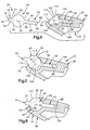
- Fig. 1 illustrates sheet material handling apparatus including a gripper drum 10.
- the gripper drum 10 is rotatable about an axis 12 in a direction indicated by the arrow 14, that is, counter-clockwise as viewed in Fig. 1.
- the gripper drum 10 includes a pair of grippers 18 and a pair of gripper seats 20. Each one of the grippers 18 cooperates with a respective gripper seat 20 to grip sheet material such as a signature 22 from a stack of signatures in a hopper 24.
- Each signature 22 is deposited in a pocket 26 in a collating conveyor 28 which moves past the gripper drum.
- a second gripper drum 10a identical to the gripper drum 10, is spaced along the collating conveyor 28 downstream from the gripper drum 10.
- the second gripper drum 10a grips signatures 22a from a second stack of signatures in a second hopper 24a.
- the signatures 22a from the second hopper 24a are deposited in the pockets 26 of the collating conveyor 28, with the signatures 22, as the pockets move past the second gripper drum 10a. In this manner, collated assemblages of signatures 22 and 22a are formed in the pockets 26.
- the gripper seat 20 (Fig. 4) is molded as one piece from a resilient material such as urethane plastic.
- the gripper seat 20 has a main body portion 40, a guide tab 42, and a removal tab 44.
- the main body portion 40, the guide tab 42, and the removal tab 44 are centered on a central plane 46 of the gripper seat 20.
- the main body portion 40 of the gripper seat 20 has a cylindrical configuration centered on an axis 50 which extends into and out of the plane of the paper as viewed in the drawings.
- the axis 50 is located on the central plane 46 of the gripper seat 20.
- the main body portion 40 of the gripper seat 20 has a cylindrical outer surface 60.
- a first cylindrical portion 62 of the outer surface 60 of the main body portion 40 of the gripper seat 20 forms a first grip surface on the gripper seat.
- a second cylindrical portion 64 of the outer surface 60 of the main body portion 40 of the gripper seat 20 forms a second grip surface on the gripper seat.
- the second grip surface 64 is disposed opposite the first grip surface 62, that is, on an opposite side of the central plane 46 of the gripper seat 20 from the first grip surface.
- the removal tab 44 of the gripper seat 20 projects from the main body portion 40 in a first direction along the central plane 46.
- the removal tab 44 has a planar, rectilinear configuration including first and second opposite side surfaces 70 and 72.
- the first side surface 70 of the removal tab 44 merges with the first grip surface 62 of the main body portion 40 of the gripper seat 20.
- the second side surface 72 of the removal tab 44 merges with the second grip surface 64 of the main body portion 40 of the gripper seat 20.
- An end surface 74 of the removal tab 44 extends between and interconnects the first and second side surfaces 70 and 72 of the removal tab.
- the removal tab 44 of the gripper seat 20 is relatively short and rigid compared to the guide tab 42 of the gripper seat.
- the guide tab 42 of the gripper seat 20 projects from the main body portion 40 in a direction opposite from the removal tab 44.
- the guide tab 42 has a planar, rectilinear configuration including first and second opposite side surfaces 80 and 82.
- the first side surface 80 of the guide tab 42 merges with the first grip surface 62 of the main body portion 40 of the gripper seat 20.
- the second side surface 82 of the guide tab 42 merges with the second grip surface 64 of the main body portion 40 of the gripper seat 20.
- a first section 84 of the guide tab 42 is disposed adjacent to the main body portion 40 of the gripper seat 20.
- a second section 86 of the guide tab 42 is spaced apart from the main body portion 40.
- An end surface 88 of the guide tab 42 extends between and interconnects the first and second side surfaces 80 and 82 of the guide tab. The end surface 88 is formed on the second section 86 of the guide tab 42.
- the thickness of the guide tab 42 that is, the distance between the surfaces 80 and 82, is the same as the thickness of the removal tab 44.
- the guide tab 42 is relatively long and bendable compared to the removal tab 44.
- One gripper seat 20 constructed in accordance with the present invention has an overall length, between the end surfaces 74 and 88, of about 3,81 cm (1.5 inches).
- the main body portion 40 of the one gripper seat 20 has a diameter of about 1,59 cm (0.625 inches).
- the axis 50 of the main body portion 40 is located about 1,27 cm (0.5 inches) from the end surface 74 of the removal tab 44 and about 2,54 cm (1.0 inches) from the end surface 88 of the guide tab 42.
- the removal tab 44 and the guide tab 42 each have a thickness of about 0,41 cm (0.16 inches).
- the one gripper seat 20 has a width (as measured in a direction into and out of the paper as viewed in the drawings) of about 2.22 cm (0.875 inches).
- the gripper drum 10 has a portion 90 for supporting the gripper seat 20 for rotation with the gripper drum about the axis 12.
- the portion 90 of the gripper drum 10 has an outer side surface 92 and a planar face surface 94.
- the gripper drum portion 90 may be a part of the drum 10 itself, or may be a separate piece secured for rotation with the gripper drum.
- the portion 90 may comprise part of an articulating arm mounted on the gripper drum 10 for pivotal movement relative to the gripper drum.
- the portion 90 of the gripper drum 10 defines a retaining pocket 100 for the main body portion 40 of the gripper seat 20.
- the retaining pocket 100 has a generally cylindrical configuration defined by first and second cylindrical surfaces 102 and 104.
- the cylindrical surfaces 102 and 104 are centered on a common axis 106 which extends into and out of the plane of the paper as viewed in the drawings.
- the cylindrical surfaces 102 and 104 have the same radius of curvature as the cylindrical outer surface 60 of the main body portion 40 of the gripper seat 20.
- a first planar surface or flat 110 extends outward from the first cylindrical surface 102 to intersect at a 90° angle the face surface 94.
- a second planar surface or flat 112 extends outward from the second cylindrical surface 104 to intersect at a 90° angle the face surface 94.
- the flats 110 and 112 extend parallel to each other and define an insertion passage 114 into the retaining pocket 100.
- the width of the passage 114 that is, the distance between the flats 110 and 112, is approximately the same as the diameter of the main body portion 40 of the gripper seat 20.
- the width of the passage 114 is substantially greater than the thickness of the removal tab 44.
- a planar guide slot 120 for receiving the guide tab 42 of the gripper seat 20, extends from the retaining pocket 100 into the gripper drum 10.
- the guide slot 120 has a rectilinear configuration defined by first and second opposite side surfaces 122 and 124 spaced equidistant from a central plane 126 of the guide slot.
- the first side surface 122 of the guide slot 120 merges with the first cylindrical surface 102 of the retaining pocket 100.
- the second side surface 124 of the guide slot 120 merges with the second cylindrical surface 104 of the retaining pocket 100.
- An end surface 128 of the guide slot 120 extends between and interconnects the first and second side surfaces 122 and 124 of the guide slot.
- the guide tab 42 on the gripper seat is inserted through the retaining pocket 100 in the gripper drum and into the guide slot 120.
- the main body portion 40 of the gripper seat 20 moves through the passage 114, between the flats 110 and 112, and into the retaining pocket 100.
- the guide tab 42 bends or deforms as seen in Fig. 5 during insertion of the main body portion 40 of the gripper seat 20 into the retaining pocket 100.
- the guide tab 42 moves into the guide slot 120 in a direction parallel to the central plane 126 of the guide slot, while the main body portion 40 of the gripper seat 20 moves into the retaining pocket 100 in a transverse direction which is parallel to the flats 110 and 112.
- the main body portion 40 of the gripper seat 20 When the main body portion 40 of the gripper seat 20 is fully received in the retaining pocket 100, the main body portion pivots relative to the guide tab 42.
- the guide tab 42 straightens, from the condition shown in Fig. 5 to the condition shown in Fig. 6.
- the axis 50 of the main body portion 40 of the gripper seat 20 is located on the axis 106 of the retaining pocket 100 of the gripper drum 10.
- the second cylindrical surface 104 on the gripper drum 10 blocks movement of the main body portion 40 of the gripper seat out of the retaining pocket 100 in the gripper drum 10.
- the resilience of the guide tab 42 prevents the main body portion 40 of the gripper seat 20 from moving back to a condition, as shown in Fig. 5, in which the main body portion can be removed from the retaining pocket 100.
- the gripper seat 20 is thus securely held in a first orientation in the retaining pocket 100 in the gripper drum 10.
- the second grip surface 64 of the gripper seat 20 is in abutting engagement with the second cylindrical surface 104 of the retaining pocket 100.
- a part 130 of the first grip surface 62 of the gripper seat 20 is in abutting engagement with the first cylindrical surface 102 of the retaining pocket 100.
- Another part 132 of the first grip surface 62 of the gripper seat 20 is exposed between the face surface 94 on the gripper drum 10 and the first side surface 70 on the removal tab 44.
- the gripper 18 During operation of the gripper drum 10, the gripper 18 has an open position spaced apart from the gripper seat 20, as seen in Fig. 2.
- the gripper 18 is movable in a known manner, from the position shown in Fig. 2 to the position shown in Fig. 3, to grip a signature 22 against the exposed part 132 of the first grip surface 62 of the gripper seat 20.
- the exposed part 132 of the first grip surface 62 of the gripper seat 20 may become worn.
- the gripper seat 20 can then be manually removed and inverted as described below to place the gripper seat 20 in a second orientation (not shown). When the gripper seat 20 is in the second orientation, a part of the second grip surface 64 is exposed.
- the removal and re-orientation operation is the reverse of the insertion operation described above. Specifically, to remove the gripper seat 20, the removal tab 44 is manually grasped and moved upward as viewed in Fig. 6. The main body portion 40 of the gripper seat 20 pivots relative to the guide tab 42 as the first section 84 of the guide tab 42 deforms. The removal tab 44 is pulled outwardly so as to pull the main body portion 40 of the gripper seat 20 out of the retaining pocket 100 through the channel 114 between the flats 110 and 112. The guide tab 42 follows. The removal and subsequent re-assembly of the gripper seat 20 are made easier because no fasteners are needed to secure the gripper seat in the drum 10.
- the gripper seat 20 is inverted and replaced in the gripper drum in the second orientation.
- the first grip surface 62 of the gripper seat is in abutting engagement with the second cylindrical surface 104 of the retaining pocket 100.
- a part of the second grip surface 64 of the gripper seat 20 is in abutting engagement with the first cylindrical surface 102 of the retaining pocket 100.
- Another part of the second grip surface 64 of the gripper seat 20 is exposed to the gripper 18.
- the gripper 18 is movable to grip a signature 22 against the exposed part of the second grip surface 64 of the gripper seat 20.
- Gripper seats of different hardnesses can be color coded, to indicate hardness by color.
Landscapes
- Engineering & Computer Science (AREA)
- Mechanical Engineering (AREA)
- Feeding Of Articles By Means Other Than Belts Or Rollers (AREA)
- Supply, Installation And Extraction Of Printed Sheets Or Plates (AREA)
- Handling Of Cut Paper (AREA)
Applications Claiming Priority (2)
| Application Number | Priority Date | Filing Date | Title |
|---|---|---|---|
| US719996 | 1996-09-25 | ||
| US08/719,996 US5901955A (en) | 1996-09-25 | 1996-09-25 | Gripper seat |
Publications (2)
| Publication Number | Publication Date |
|---|---|
| EP0832834A1 EP0832834A1 (en) | 1998-04-01 |
| EP0832834B1 true EP0832834B1 (en) | 2001-11-07 |
Family
ID=24892238
Family Applications (1)
| Application Number | Title | Priority Date | Filing Date |
|---|---|---|---|
| EP97114681A Expired - Lifetime EP0832834B1 (en) | 1996-09-25 | 1997-08-25 | Gripper Seat |
Country Status (6)
| Country | Link |
|---|---|
| US (1) | US5901955A (enExample) |
| EP (1) | EP0832834B1 (enExample) |
| JP (1) | JP4054414B2 (enExample) |
| CN (1) | CN1076701C (enExample) |
| CZ (1) | CZ292597A3 (enExample) |
| DE (1) | DE69708023T2 (enExample) |
Families Citing this family (4)
| Publication number | Priority date | Publication date | Assignee | Title |
|---|---|---|---|---|
| DE10212536A1 (de) * | 2001-04-30 | 2002-10-31 | Heidelberger Druckmasch Ag | Einrichtung zum Abstoßen bogenförmigen Materials |
| DE10355045B4 (de) * | 2002-12-20 | 2018-09-06 | Heidelberger Druckmaschinen Ag | Verfahren zur Variation eines Trommelprofils einer Vario-Trommel und Vario-Trommel zur Durchführung des Verfahrens |
| JP2005007858A (ja) * | 2003-06-18 | 2005-01-13 | Heidelberger Druckmas Ag | 被印刷体枚葉紙を処理する機械を運転する方法 |
| JP5335040B2 (ja) * | 2011-07-22 | 2013-11-06 | 富士フイルム株式会社 | 画像形成装置および画像形成方法 |
Family Cites Families (14)
| Publication number | Priority date | Publication date | Assignee | Title |
|---|---|---|---|---|
| US1208731A (en) * | 1916-04-06 | 1916-12-19 | Miehle Printing Press & Mfg | Adjustable gripper-pad. |
| CH507812A (de) * | 1969-05-13 | 1971-05-31 | Polygraph Leipzig | Vorrichtung zum Klemmen von Materialbogen an Bogenver- und -bearbeitungsmaschinen |
| US3744787A (en) * | 1970-08-11 | 1973-07-10 | Bell & Howell Co | Gripper jaw insert mistake detector |
| SU499136A1 (ru) * | 1972-06-19 | 1976-01-15 | Московский Полиграфический Институт | Листопередающее устройство |
| US3934867A (en) * | 1974-06-03 | 1976-01-27 | Pitney-Bowes, Inc. | Collating, folding and inserting system |
| CH641112A5 (de) * | 1979-10-17 | 1984-02-15 | Grapha Holding Ag | Anleger fuer druckbogen. |
| DD145900A1 (de) * | 1979-10-25 | 1981-01-14 | Peter Kahlert | Bogengreifereinrichtung |
| DE8404981U1 (de) * | 1984-02-18 | 1984-05-10 | M.A.N.- Roland Druckmaschinen AG, 6050 Offenbach | Bogengreifer fuer druckmaschinen |
| DE8514775U1 (de) * | 1985-05-20 | 1985-06-27 | Heidelberger Druckmaschinen Ag, 6900 Heidelberg | Antrieb für einen Bogentransportmechanismus am Anleger einer Rotationsdruckmaschine |
| US4721296A (en) * | 1986-05-27 | 1988-01-26 | Harris Graphics Corporation | Sheet material handling apparatus |
| US4723770A (en) * | 1986-06-20 | 1988-02-09 | Graphic Management Associates, Inc. | Straight-line insert machine |
| CH671754A5 (enExample) * | 1986-09-24 | 1989-09-29 | Grapha Holding Ag | |
| DE3821324C2 (de) * | 1988-06-24 | 1994-03-10 | Heidelberger Druckmasch Ag | Bogengreifer an Bogenrotationsdruckmaschinen |
| DE3921474A1 (de) * | 1989-06-30 | 1991-01-10 | Heidelberger Druckmasch Ag | Bogengreifereinrichtung fuer bogenrotationsdruckmaschinen |
-
1996
- 1996-09-25 US US08/719,996 patent/US5901955A/en not_active Expired - Lifetime
-
1997
- 1997-08-25 EP EP97114681A patent/EP0832834B1/en not_active Expired - Lifetime
- 1997-08-25 DE DE69708023T patent/DE69708023T2/de not_active Expired - Lifetime
- 1997-09-17 CZ CZ972925A patent/CZ292597A3/cs unknown
- 1997-09-22 CN CN97116559A patent/CN1076701C/zh not_active Expired - Fee Related
- 1997-09-25 JP JP26001297A patent/JP4054414B2/ja not_active Expired - Fee Related
Also Published As
| Publication number | Publication date |
|---|---|
| HK1008947A1 (en) | 1999-05-21 |
| US5901955A (en) | 1999-05-11 |
| DE69708023T2 (de) | 2002-06-06 |
| JPH10101248A (ja) | 1998-04-21 |
| CN1076701C (zh) | 2001-12-26 |
| DE69708023D1 (de) | 2001-12-13 |
| CZ292597A3 (cs) | 1998-05-13 |
| CN1178187A (zh) | 1998-04-08 |
| EP0832834A1 (en) | 1998-04-01 |
| JP4054414B2 (ja) | 2008-02-27 |
Similar Documents
| Publication | Publication Date | Title |
|---|---|---|
| CA2089821C (en) | Gripper for a conveying device for conveying single-sheet or multiple-sheet printed products | |
| US5803705A (en) | Disk type inverter-stacker with improved sheet handling slots for different paper weights | |
| JP3731260B2 (ja) | 給紙装置及びそれを備える画像記録機 | |
| EP0832834B1 (en) | Gripper Seat | |
| US20030218293A1 (en) | Roller and sheet delivery unit | |
| JPH0729064Y2 (ja) | 枚葉物の発行装置 | |
| US4297045A (en) | Paper feed system for a typewriter or the like | |
| US6336629B1 (en) | Idler mounting tie-bar assembly | |
| US5673911A (en) | Device for feeding sheet material | |
| US5560298A (en) | Method and apparatus for mounting a flexible plate | |
| US4726698A (en) | Device for pressing a stack of sheets against a roller drive of a papersheet separator | |
| US5671471A (en) | Sheet separating device | |
| CA2089828C (en) | Gripper for a conveying device for conveying single-sheet or multiple-sheet printed products | |
| EP0884261A3 (en) | Sheet supply and transfer device for printers | |
| JPS62215464A (ja) | シ−ト仕分け装置 | |
| JPH10101248A5 (enExample) | ||
| US20080179826A1 (en) | Feeder having an improved conveyor device for mail items | |
| EP1464600B1 (en) | Multi-positional rotatable/large substrate backstop guide | |
| EP1013587B1 (en) | A sheet conveying apparatus | |
| US6412383B1 (en) | Device for cross cutting material webs | |
| JPH024500B2 (enExample) | ||
| US5711220A (en) | Slidable stop on a product-guiding cylinder associated with a rotary printing press | |
| US20070056452A1 (en) | Material transfer vacuum device | |
| JPH0521171Y2 (enExample) | ||
| US20020063376A1 (en) | Device for alignment of stock in a printing machine |
Legal Events
| Date | Code | Title | Description |
|---|---|---|---|
| PUAI | Public reference made under article 153(3) epc to a published international application that has entered the european phase |
Free format text: ORIGINAL CODE: 0009012 |
|
| 17P | Request for examination filed |
Effective date: 19970825 |
|
| AK | Designated contracting states |
Kind code of ref document: A1 Designated state(s): BE CH DE FR GB IT LI NL |
|
| AKX | Designation fees paid |
Free format text: BE CH DE FR GB IT LI NL |
|
| RBV | Designated contracting states (corrected) |
Designated state(s): BE CH DE FR GB IT LI NL |
|
| 17Q | First examination report despatched |
Effective date: 20000529 |
|
| GRAG | Despatch of communication of intention to grant |
Free format text: ORIGINAL CODE: EPIDOS AGRA |
|
| GRAG | Despatch of communication of intention to grant |
Free format text: ORIGINAL CODE: EPIDOS AGRA |
|
| GRAH | Despatch of communication of intention to grant a patent |
Free format text: ORIGINAL CODE: EPIDOS IGRA |
|
| GRAH | Despatch of communication of intention to grant a patent |
Free format text: ORIGINAL CODE: EPIDOS IGRA |
|
| GRAA | (expected) grant |
Free format text: ORIGINAL CODE: 0009210 |
|
| AK | Designated contracting states |
Kind code of ref document: B1 Designated state(s): BE CH DE FR GB IT LI NL |
|
| PG25 | Lapsed in a contracting state [announced via postgrant information from national office to epo] |
Ref country code: NL Free format text: LAPSE BECAUSE OF FAILURE TO SUBMIT A TRANSLATION OF THE DESCRIPTION OR TO PAY THE FEE WITHIN THE PRESCRIBED TIME-LIMIT Effective date: 20011107 Ref country code: IT Free format text: LAPSE BECAUSE OF FAILURE TO SUBMIT A TRANSLATION OF THE DESCRIPTION OR TO PAY THE FEE WITHIN THE PRE;WARNING: LAPSES OF ITALIAN PATENTS WITH EFFECTIVE DATE BEFORE 2007 MAY HAVE OCCURRED AT ANY TIME BEFORE 2007. THE CORRECT EFFECTIVE DATE MAY BE DIFFERENT FROM THE ONE RECORDED.SCRIBED TIME-LIMIT Effective date: 20011107 Ref country code: FR Free format text: LAPSE BECAUSE OF FAILURE TO SUBMIT A TRANSLATION OF THE DESCRIPTION OR TO PAY THE FEE WITHIN THE PRESCRIBED TIME-LIMIT Effective date: 20011107 Ref country code: BE Free format text: LAPSE BECAUSE OF FAILURE TO SUBMIT A TRANSLATION OF THE DESCRIPTION OR TO PAY THE FEE WITHIN THE PRESCRIBED TIME-LIMIT Effective date: 20011107 |
|
| REG | Reference to a national code |
Ref country code: CH Ref legal event code: EP |
|
| REF | Corresponds to: |
Ref document number: 69708023 Country of ref document: DE Date of ref document: 20011213 |
|
| REG | Reference to a national code |
Ref country code: GB Ref legal event code: IF02 |
|
| NLV1 | Nl: lapsed or annulled due to failure to fulfill the requirements of art. 29p and 29m of the patents act | ||
| PG25 | Lapsed in a contracting state [announced via postgrant information from national office to epo] |
Ref country code: GB Free format text: LAPSE BECAUSE OF NON-PAYMENT OF DUE FEES Effective date: 20020825 |
|
| EN | Fr: translation not filed | ||
| PLBE | No opposition filed within time limit |
Free format text: ORIGINAL CODE: 0009261 |
|
| STAA | Information on the status of an ep patent application or granted ep patent |
Free format text: STATUS: NO OPPOSITION FILED WITHIN TIME LIMIT |
|
| 26N | No opposition filed | ||
| GBPC | Gb: european patent ceased through non-payment of renewal fee |
Effective date: 20020825 |
|
| PGFP | Annual fee paid to national office [announced via postgrant information from national office to epo] |
Ref country code: CH Payment date: 20100825 Year of fee payment: 14 |
|
| PGFP | Annual fee paid to national office [announced via postgrant information from national office to epo] |
Ref country code: DE Payment date: 20100827 Year of fee payment: 14 |
|
| REG | Reference to a national code |
Ref country code: CH Ref legal event code: PL |
|
| PG25 | Lapsed in a contracting state [announced via postgrant information from national office to epo] |
Ref country code: LI Free format text: LAPSE BECAUSE OF NON-PAYMENT OF DUE FEES Effective date: 20110831 Ref country code: CH Free format text: LAPSE BECAUSE OF NON-PAYMENT OF DUE FEES Effective date: 20110831 |
|
| REG | Reference to a national code |
Ref country code: DE Ref legal event code: R119 Ref document number: 69708023 Country of ref document: DE Effective date: 20120301 |
|
| PG25 | Lapsed in a contracting state [announced via postgrant information from national office to epo] |
Ref country code: DE Free format text: LAPSE BECAUSE OF NON-PAYMENT OF DUE FEES Effective date: 20120301 |