EP0832794B1 - Fastening device for an airbag cover - Google Patents
Fastening device for an airbag cover Download PDFInfo
- Publication number
- EP0832794B1 EP0832794B1 EP97115183A EP97115183A EP0832794B1 EP 0832794 B1 EP0832794 B1 EP 0832794B1 EP 97115183 A EP97115183 A EP 97115183A EP 97115183 A EP97115183 A EP 97115183A EP 0832794 B1 EP0832794 B1 EP 0832794B1
- Authority
- EP
- European Patent Office
- Prior art keywords
- locking element
- lever
- cover
- initial position
- locking
- Prior art date
- Legal status (The legal status is an assumption and is not a legal conclusion. Google has not performed a legal analysis and makes no representation as to the accuracy of the status listed.)
- Expired - Lifetime
Links
Images

Classifications
-
- B—PERFORMING OPERATIONS; TRANSPORTING
- B60—VEHICLES IN GENERAL
- B60R—VEHICLES, VEHICLE FITTINGS, OR VEHICLE PARTS, NOT OTHERWISE PROVIDED FOR
- B60R21/00—Arrangements or fittings on vehicles for protecting or preventing injuries to occupants or pedestrians in case of accidents or other traffic risks
- B60R21/02—Occupant safety arrangements or fittings, e.g. crash pads
- B60R21/16—Inflatable occupant restraints or confinements designed to inflate upon impact or impending impact, e.g. air bags
- B60R21/20—Arrangements for storing inflatable members in their non-use or deflated condition; Arrangement or mounting of air bag modules or components
- B60R21/217—Inflation fluid source retainers, e.g. reaction canisters; Connection of bags, covers, diffusers or inflation fluid sources therewith or together
-
- B—PERFORMING OPERATIONS; TRANSPORTING
- B60—VEHICLES IN GENERAL
- B60R—VEHICLES, VEHICLE FITTINGS, OR VEHICLE PARTS, NOT OTHERWISE PROVIDED FOR
- B60R21/00—Arrangements or fittings on vehicles for protecting or preventing injuries to occupants or pedestrians in case of accidents or other traffic risks
- B60R21/02—Occupant safety arrangements or fittings, e.g. crash pads
- B60R21/16—Inflatable occupant restraints or confinements designed to inflate upon impact or impending impact, e.g. air bags
- B60R21/20—Arrangements for storing inflatable members in their non-use or deflated condition; Arrangement or mounting of air bag modules or components
- B60R21/203—Arrangements for storing inflatable members in their non-use or deflated condition; Arrangement or mounting of air bag modules or components in steering wheels or steering columns
Definitions
- the invention relates to a device for attaching a gas bag cover on a vehicle part, wherein the device as a positive Snap connection is formed, which is connected to a at the Airbag cover molded fastening web attacks.
- An airbag cover for example, on the steering wheel hub or, to cover a passenger gas bag, attached to the dashboard.
- a generic device for Attaching the gas bag cover is known as a snap-in connection is trained.
- the gas bag cover integrally formed on the inside, hook-shaped fastening webs on, in the mounted state behind a vehicle part.
- the gas bag cover is for assembly just put over the gas bag and pressed.
- the fastening bars must be designed so that the cover when unfolding the Do not release gas bags from their anchorage or even tear them out of their anchorage becomes.
- the invention provides a device that provides more security against Loosening or destroying the anchoring of a gas bag cover offers as the well-known.
- This is in a device of the aforementioned Art according to the invention achieved in that the vehicle part by a a spring element from a basic in a locking position movable Locking element is mounted and that a locking mechanism is provided, which the spring element in the basic position on the drive prevents the locking element and the by pressing the cover can be solved when mounting the same.
- the fastening web when pressing the airbag cover during the assembly process not bent laterally to snap back after sliding along the vehicle part and to back this up.
- An intended in the invention Spring element for driving the locking element ensures that the locking element displaced by a considerable displacement can be and thus the mounting bar large area and detected safer than the known device. This can also be done the pressure exerted on the wall in the region of the recess surface pressure decrease when unfolding the gas bag.
- the locking element is a translationally displaceable mounted slider body, which in a recess in the fastening web intervenes.
- the locking mechanism comprises according to the preferred embodiment a lever which holds the locking element in the basic position, wherein the lever is preferably a cantilevered leaf spring is. Through the mounting bar is the lever when mounting the cover deflected, so that relocate the locking element can.
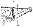
- FIG. 1 shows an airbag cover 1, which is an airbag module 3, which is fixed to a steering wheel hub 5 covers.
- an airbag cover 1 On the Inside the cover 1 are on opposite sides of the airbag module 3 two protruding, plate-like fastening webs 7 integrally formed.
- the cover 1 is fixed by a snap connection on the Steering wheel hub 5 is held.
- the locking element 11 is mounted translationally displaceable on the steering wheel hub 5.
- it has two parallel slots 15 through which in each case the shank of an associated bolt 17 extends, the at its lower end a locking ring 19 carries.
- a locking mechanism in Shape of a lever 21 held This consists of a leaf spring, which is made of a H-shaped, punched spring plate. Two parallel ends of the lever 21 are between each a retaining ring 19 and the locking member 11 clamped so that the Lever 21 is clamped on one side. Outside of this restraint is the lever 1 is bent in a U-shape and extends in the direction of the fastening web 7, where he with his two free ends at the Underside.
- the locking mechanism serves to the locking element 11 in the normal position in which the cover 1 is not yet is mounted to hold. In this basic position is the locking element 11 compared to the locking position shown in the figures moved towards the center of the steering wheel.
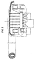
- a compression spring 23 is seated on a on the locking element eleventh molded, extending towards the center of the steering wheel tongue 23 (see Figure 2) and is based in the basic position in which they is compressed, on the one hand on the steering wheel hub 5 and on the other at an intermediate web 25 of the H-shaped lever 21 from.
- Figure 1 is the basic position of the lever 21 shown with dotted lines.
- the compression spring 23 is by means of a latching mechanism forming lever 21 on the displacement of the locking element eleventh prevented.
- the device for securing the airbag cover 1 can again be solved by the locking element 13 in the normal position pushed and the cover 1 is removed, so that the lever 21st can spring back to hold the compression spring 23.
Landscapes
- Engineering & Computer Science (AREA)
- Mechanical Engineering (AREA)
- Air Bags (AREA)
- Steering Controls (AREA)
Description
Die Erfindung betrifft eine Einrichtung zum Befestigen einer Gassack-Abdeckung an einem Fahrzeugteil, wobei die Einrichtung als formschlüssige Schnapp-Verbindung ausgebildet ist, die an einem an der Gassack-Abdeckung angeformten Befestigungssteg angreift.The invention relates to a device for attaching a gas bag cover on a vehicle part, wherein the device as a positive Snap connection is formed, which is connected to a at the Airbag cover molded fastening web attacks.
Eine Gassack-Abdeckung wird beispielsweise an der Lenkradnabe oder, zur Abdeckung eines Beifahrer-Gassacks, am Armaturenbrett befestigt. Aus der EP 0 669 230 A1 ist eine gattungsgemäße Einrichtung zum Befestigen der Gassack-Abdeckung bekannt, die als Schnapp-Verbindung ausgebildet ist. Dazu weist die Gassack-Abdeckung innenseitig angeformte, hakenförmige Befestigungsstege auf, die im montierten Zustand ein Fahrzeugteil hintergreifen. Die Gassack-Abdeckung wird zur Montage nur über den Gassack gesetzt und angedrückt. Die Befestigungsstege müssen so ausgeführt sein, daß sich die Abdeckung beim Entfalten des Gassacks nicht aus ihrer Verankerung löst oder gar aus ihr herausgerissen wird.An airbag cover, for example, on the steering wheel hub or, to cover a passenger gas bag, attached to the dashboard. From EP 0 669 230 A1 a generic device for Attaching the gas bag cover is known as a snap-in connection is trained. For this purpose, the gas bag cover integrally formed on the inside, hook-shaped fastening webs on, in the mounted state behind a vehicle part. The gas bag cover is for assembly just put over the gas bag and pressed. The fastening bars must be designed so that the cover when unfolding the Do not release gas bags from their anchorage or even tear them out of their anchorage becomes.
Die Erfindung schafft eine Einrichtung, die mehr Sicherheit gegen Lösen oder Zerstören der Verankerung einer Gassackabdeckung bietet als die bekannte. Dies wird bei einer Einrichtung der eingangs genannten Art erfindungsgemäß dadurch erreicht, daß am Fahrzeugteil ein durch ein Federelement aus einer Grund- in eine Verriegelungsstellung bewegbares Verriegelungselement gelagert ist und daß ein Rastmechanismus vorgesehen ist, der das Federelement in der Grundstellung am Antrieb des Verriegelungselements hindert und der durch das Andrücken der Abdeckung beim Montieren derselben gelöst werden kann.The invention provides a device that provides more security against Loosening or destroying the anchoring of a gas bag cover offers as the well-known. This is in a device of the aforementioned Art according to the invention achieved in that the vehicle part by a a spring element from a basic in a locking position movable Locking element is mounted and that a locking mechanism is provided, which the spring element in the basic position on the drive prevents the locking element and the by pressing the cover can be solved when mounting the same.
Bei der erfindungsgemäßen Einrichtung wird der Befestigungssteg beim Andrücken der Gassack-Abdeckung während des Montagevorgangs nicht seitlich gebogen, um nach dem Entlanggleiten am Fahrzeugteil zurückzuschnappen und dieses zu hintergreifen. Ein bei der Erfindung vorgesehenes Federelement zum Antrieb des Verriegelungselements sorgt dafür, daß das Verriegelungselement um einen erheblichen Verschiebeweg verlagert werden kann und somit den Befestigungssteg großflächiger und sicherer erfaßt als die bekannte Einrichtung. Dadurch läßt sich auch die auf die Wandung im Bereich der Ausnehmung ausgeübte Flächenpressung beim Entfalten des Gassacks verringern.In the device according to the invention, the fastening web when pressing the airbag cover during the assembly process not bent laterally to snap back after sliding along the vehicle part and to back this up. An intended in the invention Spring element for driving the locking element ensures that the locking element displaced by a considerable displacement can be and thus the mounting bar large area and detected safer than the known device. This can also be done the pressure exerted on the wall in the region of the recess surface pressure decrease when unfolding the gas bag.
Vorzugsweise ist das Verriegelungselement ein translatorisch verschiebbar gelagerter Schieberkörper, der in eine Ausnehmung im Befestigungssteg eingreift.Preferably, the locking element is a translationally displaceable mounted slider body, which in a recess in the fastening web intervenes.
Der Rastmechanismus umfaßt gemäß der bevorzugten Ausführungsform einen Hebel, der das Verriegelungselement in der Grundstellung hält, wobei der Hebel vorzugsweise eine einseitig eingespannte Blattfeder ist. Durch den Befestigungssteg wird der Hebel beim Montieren der Abdeckung ausgelenkt, so daß sich das Verriegelungselement verlagern kann.The locking mechanism comprises according to the preferred embodiment a lever which holds the locking element in the basic position, wherein the lever is preferably a cantilevered leaf spring is. Through the mounting bar is the lever when mounting the cover deflected, so that relocate the locking element can.
Weitere Merkmale und Vorteile der Erfindung ergeben sich aus der nachfolgenden Beschreibung und aus der nachfolgenden Zeichnung, auf die Bezug genommen wird. In den Zeichnungen zeigen:
- Figur 1 einen Halbschnitt durch eine Gassack-Abdeckung, die mit der erfindungsgemäßen Einrichtung an einer Lenkradnabe befestigt ist;
Figur 2 eine Schnittansicht auf die Gassack-Abdeckung nach Figur 1 von oben, in der die Teile der Einrichtung hervorgehoben sind, wobei die Ansichten auf der linken und der rechten Hälfte der Zeichnung horizontale Schnitte in unterschiedlichen Ebenen darstellen; und- Figur 3 eine Schnittansicht längs der Linie III-III in Figur 1.
- Figure 1 shows a half section through an airbag cover, which is fastened with the device according to the invention to a steering wheel hub;
- Figure 2 is a sectional view of the airbag cover of Figure 1 from above, in which the parts of the device are highlighted, the views on the left and right half of the drawing represent horizontal sections in different planes. and
- 3 shows a sectional view along the line III-III in Figure 1.
In Figur 1 ist eine Gassack-Abdeckung 1 gezeigt, die ein Gassackmodul 3, das an einer Lenkradnabe 5 befestigt ist, abdeckt. Auf der Innenseite der Abdeckung 1 sind auf gegenüberliegenden Seiten des Gassackmoduls 3 zwei abstehende, plattenartige Befestigungsstege 7 angeformt. Der in Figur 1 gezeigte rechte Befestigungssteg 7 weist im Bereich seines unteren Endes voneinander beabstandete schlitzförmige Ausnehmungen 9 (vgl. auch Figur 3) auf.FIG. 1 shows an airbag cover 1, which is an airbag module 3, which is fixed to a steering wheel hub 5 covers. On the Inside the cover 1 are on opposite sides of the airbag module 3 two protruding, plate-like fastening webs 7 integrally formed. The right fastening web 7 shown in FIG Area of its lower end spaced slot-shaped Recesses 9 (see also Figure 3) on.
Die Abdeckung 1 wird durch eine Schnapp-Verbindung lagefest an der
Lenkradnabe 5 gehalten. Neben den Ausnehmungen 9 weist die Schnapp-Verbindung
ein kammartiges, als Schieberkörper ausgebildetes Verriegelungselement
11 auf, dessen Zinken 13 jeweils in eine zugeordnete Ausnehmung
9 eingreifen, wie Figur 2 zu entnehmen ist. Das Verriegelungselement
11 ist translatorisch verschiebbar an der Lenkradnabe 5 gelagert.
Hierzu weist es zwei parallele Langlöcher 15 auf, durch die
sich jeweils der Schaft eines zugeordneten Bolzens 17 erstreckt, der
an seinem unteren Ende einen Sicherungsring 19 trägt. Im Zwischenraum
zwischen der Unterseite der Wandung der Lenkradnabe 5, in der die
Bolzen 17 stecken, und der Oberseite der Sicherungsringe 19 erstreckt
sich das so geführte Verriegelungselement 11.The cover 1 is fixed by a snap connection on the
Steering wheel hub 5 is held. In addition to the recesses 9 has the snap connection
a comb-like, designed as a slider
Durch die Bolzen 17 wird zusätzlich noch ein Rastmechanismus in
Form eines Hebels 21 gehalten. Dieser besteht aus einer Blattfeder,
die aus einem H-förmigen, ausgestanzten Federblech hergestellt ist.
Zwei parallele Enden des Hebels 21 sind zwischen jeweils einem Sicherungsring
19 und dem Verriegelungselement 11 geklemmt, so daß der
Hebel 21 einseitig eingespannt ist. Außerhalb dieser Einspannung ist
der Hebel 1 U-förmig gebogen und erstreckt sich in Richtung des Befestigungsstegs
7, an dem er mit seinen beiden freien Enden an dessen
Unterseite anliegt. Der Rastmechanismus dient dazu, das Verriegelungselement
11 in der Grundstellung, in der die Abdeckung 1 noch nicht
montiert ist, zu halten. In dieser Grundstellung ist das Verriegelungselement
11 im Vergleich zu der in den Figuren gezeigten Verriegelungsstellung
in Richtung Lenkradmitte verschoben. By the
Eine Druckfeder 23 sitzt auf einer am Verriegelungselement 11
angeformten, sich in Richtung Mitte des Lenkrades erstreckenden Zunge
23 (vgl. Figur 2) und stützt sich in der Grundstellung, in der sie
zusammengedrückt ist, einerseits an der Lenkradnabe 5 und andererseits
an einem Zwischensteg 25 des H-förmigen Hebels 21 ab. In Figur 1 ist
die Grundstellung des Hebels 21 mit strichpunktierten Linien dargestellt.
Die Druckfeder 23 wird mittels des einen Rastmechanismus
bildenden Hebels 21 am Verschieben des Verriegelungselements 11
gehindert.A
Zum Montieren der Abdeckung 1 wird diese einfach auf die Lenkradnabe
5 gedrückt. Die Befestigungsstege 7 werden dabei in eine schlitzartige
Führung 27 in der Lenkradnabe 5 gesteckt. In das untere Ende
der Führung 27 ragen zwei freie Enden des Hebels 21, wie anhand der
mit strichpunktierten Linien gezeichneten Stellung des Hebels 21 in
Figur 1 zu erkennen ist. Durch das Einführen des Befestigungsstegs 7
wird der Hebel 21 nach unten gedrückt, bis schließlich der Zwischensteg
25 die Druckfeder 23 freigibt. Diese verschiebt das Verriegelungselement
11 abrupt in die Verriegelungsstellung nach außen, in der
sich die Zinken 13 durch die Ausnehmungen 9 erstrecken. Außenseitig
stützen sich die Zinken 13 mit ihren freien Enden an einem Abschnitt
der Lenkradnabe 5 ab. Der Befestigungssteg 11 ist dadurch verriegelt,
und die Einrichtung löst sich auch bei Vibrationen nicht.To mount the cover 1, this is easy on the steering wheel hub
5 pressed. The fastening webs 7 are in a slot-like
Guide 27 inserted in the steering wheel hub 5. In the lower end
the guide 27 protrude two free ends of the
Die Einrichtung zum Befestigen der Gassack-Abdeckung 1 kann wieder
gelöst werden, indem das Verriegelungselement 13 in die Grundstellung
geschoben und die Abdeckung 1 abgenommen wird, so daß der Hebel 21
zurückfedern kann, um die Druckfeder 23 zu halten.The device for securing the airbag cover 1 can again
be solved by the
Aufgrund der formschlüssigen Verriegelung und der großen Anlageflächen
zwischen dem Verriegelungselement 11 und dem Befestigungssteg
7 entstehen beim Aufreißen der Abdeckung 1 während des Entfaltens des
Gassacks keine zu hohen Flächenpressungen, die dazu führen könnten,
daß die Ausnehmungen 9 ausreißen.Due to the positive lock and the large contact surfaces
between the
Claims (6)
- A device for fastening a gas bag cover (1) to a vehicle part, the device being designed in the form of an interlocking snap connection that engages an attachment rib (7) formed integrally with the gas bag cover (1), characterised in that mounted on the vehicle part is a locking element (11) which is movable by a spring element (23) out of an initial position into a locking position, and in that a detent mechanism is provided which prevents the spring element (23) from driving the locking element (11) when in the initial position and which may be released by pressing the cover (1) on during fitting same.
- The device as claimed in claim 1, characterised in that the locking element (11) is designed in the form of a slide body which is mounted for sliding movement in translation and engages a recess (9) in the attachment rib (7).
- The device as claimed in claim 2, characterised in that the slide body has a comb-like configuration having prongs (13) engaging into associated recesses (9) in the attachment rib (7).
- The device as claimed in any of the preceding claims, characterised in that the detent mechanism comprises a lever (21) holding the locking element (11) in the initial position, the lever (21) being deflected by the attachment rib (7) during fitting of the cover (1) and permitting the displacement of the locking element (11).
- The device as claimed in claim 4, characterised in that the lever (21) is designed in the form of a plate spring fixed at one end.
- The device as claimed in claim 5, characterised in that the lever is an H-shaped, punched-out piece of spring steel sheet having an intermediate rib (25) which engages the spring element (23) in the initial position.
Applications Claiming Priority (2)
| Application Number | Priority Date | Filing Date | Title |
|---|---|---|---|
| DE29616914U DE29616914U1 (en) | 1996-09-27 | 1996-09-27 | Device for attaching an airbag cover |
| DE29616914U | 1996-09-27 |
Publications (3)
| Publication Number | Publication Date |
|---|---|
| EP0832794A2 EP0832794A2 (en) | 1998-04-01 |
| EP0832794A3 EP0832794A3 (en) | 2000-09-06 |
| EP0832794B1 true EP0832794B1 (en) | 2005-04-27 |
Family
ID=8029873
Family Applications (1)
| Application Number | Title | Priority Date | Filing Date |
|---|---|---|---|
| EP97115183A Expired - Lifetime EP0832794B1 (en) | 1996-09-27 | 1997-09-02 | Fastening device for an airbag cover |
Country Status (6)
| Country | Link |
|---|---|
| US (1) | US5899487A (en) |
| EP (1) | EP0832794B1 (en) |
| JP (1) | JPH10100841A (en) |
| KR (1) | KR19980024851A (en) |
| DE (2) | DE29616914U1 (en) |
| ES (1) | ES2117606T3 (en) |
Families Citing this family (14)
| Publication number | Priority date | Publication date | Assignee | Title |
|---|---|---|---|---|
| DE29706246U1 (en) * | 1997-04-08 | 1997-08-07 | Trw Occupant Restraint Systems Gmbh, 73551 Alfdorf | Airbag module for a vehicle occupant restraint system |
| EP0872401B1 (en) | 1997-04-16 | 2003-10-01 | Volkswagen Aktiengesellschaft | Steering column for passenger protection devices and safety steering assemblies |
| DE29805207U1 (en) | 1998-03-23 | 1998-06-04 | TRW Automotive Safety Systems GmbH, 63743 Aschaffenburg | Steering wheel with an airbag |
| DE19855838B4 (en) * | 1998-12-03 | 2006-09-21 | Leopold Kostal Gmbh & Co. Kg | Steering wheel module comprising a steering wheel and a steering wheel insert |
| JP2002538031A (en) | 1998-12-21 | 2002-11-12 | ダグラス オートテック コーポレーション | Non-Newtonian fluid locking device for vehicles |
| US6260876B1 (en) | 2000-01-21 | 2001-07-17 | Patent Holding Company | Thermoplastic air bag cover mountable onto an air bag container assembly |
| US6994372B2 (en) * | 2002-08-01 | 2006-02-07 | Key Safety Systems, Inc. | Air bag cover with articulated tear seam |
| US6863301B2 (en) * | 2001-02-23 | 2005-03-08 | Key Safety Systems, Inc. | Driver side air bag module with annular air bag and centrally disposed control module |
| DE20216754U1 (en) * | 2002-10-30 | 2003-03-20 | TRW Automotive Safety Systems GmbH & Co. KG, 63743 Aschaffenburg | Airbag module and vehicle steering wheel with an airbag module |
| DE10325435B4 (en) * | 2003-06-05 | 2009-11-12 | GM Global Technology Operations, Inc., Detroit | Attaching a passenger-side airbag module |
| JP2005255153A (en) * | 2004-03-12 | 2005-09-22 | Takata Corp | Air bag module |
| JP4836494B2 (en) * | 2005-06-08 | 2011-12-14 | 芦森工業株式会社 | Airbag device |
| AU2006267780B2 (en) | 2005-07-07 | 2011-07-07 | Ashimori Industry Co., Ltd. | Air bag device |
| GB2433234A (en) * | 2005-12-08 | 2007-06-20 | Autoliv Dev | A mounting arrangement for an airbag |
Family Cites Families (5)
| Publication number | Priority date | Publication date | Assignee | Title |
|---|---|---|---|---|
| JPH05131886A (en) * | 1991-11-11 | 1993-05-28 | Takata Kk | Module cover fitting structure for air bag device |
| US5439246A (en) * | 1994-02-07 | 1995-08-08 | Morton Internatinal, Inc. | Multi-directional air bag module door attachment |
| DE4434685A1 (en) * | 1994-07-19 | 1996-04-04 | Takata Europ Gmbh | Airbag arrangement |
| US5584501A (en) * | 1995-09-15 | 1996-12-17 | Trw Inc. | Vehicle occupant restraint apparatus |
| US5669626A (en) * | 1996-04-08 | 1997-09-23 | Ford Motor Company | Inflatable occupant restraint system |
-
1996
- 1996-09-27 DE DE29616914U patent/DE29616914U1/en not_active Expired - Lifetime
-
1997
- 1997-09-02 DE DE59712282T patent/DE59712282D1/en not_active Expired - Fee Related
- 1997-09-02 EP EP97115183A patent/EP0832794B1/en not_active Expired - Lifetime
- 1997-09-02 ES ES97115183T patent/ES2117606T3/en not_active Expired - Lifetime
- 1997-09-16 US US08/931,734 patent/US5899487A/en not_active Expired - Fee Related
- 1997-09-23 KR KR1019970048123A patent/KR19980024851A/en not_active Application Discontinuation
- 1997-09-26 JP JP9262223A patent/JPH10100841A/en active Pending
Also Published As
| Publication number | Publication date |
|---|---|
| ES2117606T1 (en) | 1998-08-16 |
| EP0832794A3 (en) | 2000-09-06 |
| EP0832794A2 (en) | 1998-04-01 |
| KR19980024851A (en) | 1998-07-06 |
| DE59712282D1 (en) | 2005-06-02 |
| DE29616914U1 (en) | 1997-01-30 |
| US5899487A (en) | 1999-05-04 |
| ES2117606T3 (en) | 2005-10-16 |
| JPH10100841A (en) | 1998-04-21 |
Similar Documents
| Publication | Publication Date | Title |
|---|---|---|
| EP0832794B1 (en) | Fastening device for an airbag cover | |
| EP2123918B1 (en) | Fastening device | |
| EP2576319B1 (en) | Spring element | |
| DE69413706T2 (en) | PRE-ASSEMBLED CARRIER UNIT FOR THE FUNCTIONAL PARTS OF A SEAT BELT SYSTEM | |
| DE102005035009B3 (en) | Adjustable steering column for motor vehicle, has segment that lies in area of recess in closed condition of fixing unit during through-slipping of operating unit, extends into recess and lies opposite to edge of recess | |
| DE19912267C2 (en) | Locking device for connecting two components of a motor vehicle | |
| WO2011072311A1 (en) | Steering column for a motor vehicle | |
| WO2008155082A1 (en) | Fixing system | |
| EP1957341A1 (en) | Adjustable steering column for a motor vehicle | |
| DE3012937A1 (en) | BELT LOCK FOR A SAFETY BELT | |
| DE3447817A1 (en) | HEIGHT ADJUSTMENT DEVICE FOR THE FITTING OF A SAFETY BELT | |
| EP0790153B1 (en) | Airbag module fastening | |
| EP1251042A2 (en) | Airbag module | |
| DE102012208562A1 (en) | Driving structure for connecting window pane to window lifter for motor car, has power window device to apply compressive force generating torque in direction of engagement of positive-locking elements into mating form-fit elements | |
| WO2009086897A2 (en) | Mounting aid, cable pull adjuster comprising a mounting aid and mounting method using said adjuster | |
| DE2519770A1 (en) | BUCKLE CLOSURE IN PARTICULAR FOR A VEHICLE SEAT BELT SYSTEM | |
| EP0974757B1 (en) | Fastening device for flat components | |
| EP1147949B1 (en) | Air bag module | |
| EP0853028B1 (en) | Adjusting device for the guide loop of a vehicle seat belt system | |
| DE3328798C2 (en) | ||
| DE102008031880B4 (en) | Fastener for the strap of a side airbag assembly | |
| EP1060959B1 (en) | Guide loop height-adjusting device for a vehicle seat belt | |
| EP0686102B1 (en) | Steering column switch for motor vehicles | |
| DE3516059C2 (en) | Height adjustment device for a deflection or fastening fitting | |
| EP3183159B1 (en) | Steering clolumn for a vehicle |
Legal Events
| Date | Code | Title | Description |
|---|---|---|---|
| PUAI | Public reference made under article 153(3) epc to a published international application that has entered the european phase |
Free format text: ORIGINAL CODE: 0009012 |
|
| AK | Designated contracting states |
Kind code of ref document: A2 Designated state(s): DE ES FR GB IT |
|
| AX | Request for extension of the european patent |
Free format text: AL;LT;LV;RO;SI |
|
| ITCL | It: translation for ep claims filed |
Representative=s name: DR. ING. A. RACHELI & C. |
|
| GBC | Gb: translation of claims filed (gb section 78(7)/1977) | ||
| RAP1 | Party data changed (applicant data changed or rights of an application transferred) |
Owner name: TRW OCCUPANT RESTRAINT SYSTEMS GMBH & CO. KG |
|
| EL | Fr: translation of claims filed | ||
| REG | Reference to a national code |
Ref country code: ES Ref legal event code: BA2A Ref document number: 2117606 Country of ref document: ES Kind code of ref document: T1 |
|
| PUAL | Search report despatched |
Free format text: ORIGINAL CODE: 0009013 |
|
| AK | Designated contracting states |
Kind code of ref document: A3 Designated state(s): AT BE CH DE DK ES FI FR GB GR IE IT LI LU MC NL PT SE |
|
| AX | Request for extension of the european patent |
Free format text: AL;LT;LV;RO;SI |
|
| RIN1 | Information on inventor provided before grant (corrected) |
Inventor name: FISCHER, ANTON |
|
| 17P | Request for examination filed |
Effective date: 20010214 |
|
| AKX | Designation fees paid |
Free format text: DE ES FR GB IT |
|
| GRAP | Despatch of communication of intention to grant a patent |
Free format text: ORIGINAL CODE: EPIDOSNIGR1 |
|
| GRAS | Grant fee paid |
Free format text: ORIGINAL CODE: EPIDOSNIGR3 |
|
| GRAA | (expected) grant |
Free format text: ORIGINAL CODE: 0009210 |
|
| AK | Designated contracting states |
Kind code of ref document: B1 Designated state(s): DE ES FR GB IT |
|
| PG25 | Lapsed in a contracting state [announced via postgrant information from national office to epo] |
Ref country code: GB Free format text: LAPSE BECAUSE OF FAILURE TO SUBMIT A TRANSLATION OF THE DESCRIPTION OR TO PAY THE FEE WITHIN THE PRESCRIBED TIME-LIMIT Effective date: 20050427 |
|
| RAP1 | Party data changed (applicant data changed or rights of an application transferred) |
Owner name: TRW AUTOMOTIVE GMBH |
|
| REG | Reference to a national code |
Ref country code: GB Ref legal event code: FG4D Free format text: NOT ENGLISH |
|
| REF | Corresponds to: |
Ref document number: 59712282 Country of ref document: DE Date of ref document: 20050602 Kind code of ref document: P |
|
| REG | Reference to a national code |
Ref country code: ES Ref legal event code: FG2A Ref document number: 2117606 Country of ref document: ES Kind code of ref document: T3 |
|
| GBV | Gb: ep patent (uk) treated as always having been void in accordance with gb section 77(7)/1977 [no translation filed] |
Effective date: 20050427 |
|
| PLBE | No opposition filed within time limit |
Free format text: ORIGINAL CODE: 0009261 |
|
| STAA | Information on the status of an ep patent application or granted ep patent |
Free format text: STATUS: NO OPPOSITION FILED WITHIN TIME LIMIT |
|
| ET | Fr: translation filed | ||
| 26N | No opposition filed |
Effective date: 20060130 |
|
| PGFP | Annual fee paid to national office [announced via postgrant information from national office to epo] |
Ref country code: ES Payment date: 20060913 Year of fee payment: 10 |
|
| PGFP | Annual fee paid to national office [announced via postgrant information from national office to epo] |
Ref country code: IT Payment date: 20070913 Year of fee payment: 11 |
|
| PGFP | Annual fee paid to national office [announced via postgrant information from national office to epo] |
Ref country code: FR Payment date: 20070904 Year of fee payment: 11 |
|
| REG | Reference to a national code |
Ref country code: ES Ref legal event code: FD2A Effective date: 20070903 |
|
| PG25 | Lapsed in a contracting state [announced via postgrant information from national office to epo] |
Ref country code: ES Free format text: LAPSE BECAUSE OF NON-PAYMENT OF DUE FEES Effective date: 20070903 |
|
| PGFP | Annual fee paid to national office [announced via postgrant information from national office to epo] |
Ref country code: DE Payment date: 20080930 Year of fee payment: 12 |
|
| REG | Reference to a national code |
Ref country code: FR Ref legal event code: ST Effective date: 20090529 |
|
| PG25 | Lapsed in a contracting state [announced via postgrant information from national office to epo] |
Ref country code: IT Free format text: LAPSE BECAUSE OF NON-PAYMENT OF DUE FEES Effective date: 20080902 |
|
| PG25 | Lapsed in a contracting state [announced via postgrant information from national office to epo] |
Ref country code: FR Free format text: LAPSE BECAUSE OF NON-PAYMENT OF DUE FEES Effective date: 20080930 |
|
| PG25 | Lapsed in a contracting state [announced via postgrant information from national office to epo] |
Ref country code: DE Free format text: LAPSE BECAUSE OF NON-PAYMENT OF DUE FEES Effective date: 20100401 |