EP0831477B1 - Datenspeicher - Google Patents
Datenspeicher Download PDFInfo
- Publication number
- EP0831477B1 EP0831477B1 EP96306933A EP96306933A EP0831477B1 EP 0831477 B1 EP0831477 B1 EP 0831477B1 EP 96306933 A EP96306933 A EP 96306933A EP 96306933 A EP96306933 A EP 96306933A EP 0831477 B1 EP0831477 B1 EP 0831477B1
- Authority
- EP
- European Patent Office
- Prior art keywords
- data
- track
- tape
- main
- trigger signal
- Prior art date
- Legal status (The legal status is an assumption and is not a legal conclusion. Google has not performed a legal analysis and makes no representation as to the accuracy of the status listed.)
- Expired - Lifetime
Links
Images


Classifications
-
- G—PHYSICS
- G11—INFORMATION STORAGE
- G11B—INFORMATION STORAGE BASED ON RELATIVE MOVEMENT BETWEEN RECORD CARRIER AND TRANSDUCER
- G11B27/00—Editing; Indexing; Addressing; Timing or synchronising; Monitoring; Measuring tape travel
- G11B27/10—Indexing; Addressing; Timing or synchronising; Measuring tape travel
- G11B27/19—Indexing; Addressing; Timing or synchronising; Measuring tape travel by using information detectable on the record carrier
- G11B27/28—Indexing; Addressing; Timing or synchronising; Measuring tape travel by using information detectable on the record carrier by using information signals recorded by the same method as the main recording
- G11B27/30—Indexing; Addressing; Timing or synchronising; Measuring tape travel by using information detectable on the record carrier by using information signals recorded by the same method as the main recording on the same track as the main recording
- G11B27/3027—Indexing; Addressing; Timing or synchronising; Measuring tape travel by using information detectable on the record carrier by using information signals recorded by the same method as the main recording on the same track as the main recording used signal is digitally coded
-
- G—PHYSICS
- G11—INFORMATION STORAGE
- G11B—INFORMATION STORAGE BASED ON RELATIVE MOVEMENT BETWEEN RECORD CARRIER AND TRANSDUCER
- G11B20/00—Signal processing not specific to the method of recording or reproducing; Circuits therefor
- G11B20/10—Digital recording or reproducing
- G11B20/10009—Improvement or modification of read or write signals
Definitions
- This invention relates to methods and apparatus for data storage, and particularly, though not exclusively, to methods and apparatus for controlling reading of data from elongate magnetic tape media in a helical scan tape drive.
- DDS Digital Data Storage
- an elongate recording medium comprising tape coated with a magnetic medium is moved by a motor-driven capstan along a path wrapped partially around a transducer comprising a rotating drum carrying one or more electromagnetic heads.
- the plane of rotation of the drum is disposed at an angle to the plane of movement of the tape, so that each head traverses the tape along successive tracks extending across the width of the tape at an angle to its centreline.
- an adaptive filter automatically adjusts its response according to certain properties of the incoming signal.
- Adaptive filters are well-known and an example of an adaptive filter used in a backup storage device can be seen in Applicants' US Patent No. 5150379.
- a typical characteristic of such a filter is a tendency to adopt an undesirable response when presented with a signal which has a spectral content which differs from the normal data signal.
- each track is determined during recording of data on the tape by the position relative to the tape of write heads on the drum.
- the rotary head drum generates a position signal at one or more predetermined angular positions which is used to control the motion of the media.
- This drum position signal is also used as a reference for the generation of a timing signal to enable and inhibit adaption of the filter characteristics according to the position of the read head in the track.
- the present invention aims to overcome this limitation.
- magnetic tape storage apparatus for reading data from and writing data to a storage medium, wherein the data is written to the medium in tracks, each track comprising a preamble followed by main data and including a predetermined trigger signal pattern, the apparatus comprising:
- adaptive filtering is triggered on commencement of data with spectral characteristics suitable for adaption of the filter.
- the main data of each track comprises data fragments each having a header containing ancillary information wherein at least a header in an initial data fragment of the main data in the track comprises the predetermined trigger signal pattern.
- at least the header of the first data fragment of the main data in the track comprises the predetermined trigger signal pattern.
- the predetermined trigger signal pattern is also used to control the motion of the medium.
- the data storage apparatus now to be described utilizes a helical scan technique for storing data in oblique tracks on a recording tape in a format similar to that used for the storage of PCM audio data according to the DAT Conference Standard (June 1987, Electronic Industries Association of Japan, Tokyo, Japan).
- the present apparatus is, however, adapted for storing computer data rather than digitized audio information.
- Figure 1 shows the basic layout of a helical-scan tape deck 11 in which tape 10 from a tape cartridge 17 passes at a predetermined angle across a rotary head drum 12 with a wrap angle of approximately 90°.
- the tape 10 is moved in the direction indicated by arrow T from a supply reel 13 to a take-up reel 14 by rotation of a capstan 15 against which the tape is pressed by a pinch roller 16; at the same time, the head drum is rotated in the sense indicated by arrow R.
- the head drum 12 houses two read/write heads HA, HB angularly spaced by 180°. In known manner, these heads HA, HB are arranged to write overlapping oblique tracks 20, 21 respectively across the tape 10 as shown in Figure 2.
- the track written by head HA has a positive azimuth while that written by head HB has a negative azimuth.
- Each pair of positive and negative azimuth tracks, 20, 21 constitutes a frame.
- each track comprises two marginal areas 22 and a main area 25.
- the main area 25 is used to store data provided to the apparatus (main data), together with certain auxiliary information.
- the items of auxiliary information are known as sub codes and relate, for example, to the logical organization of the main data, its mapping onto the tape, certain recording parameters (such as format identity, tape parameters etc.), and tape usage history.
- the main area 25 also includes synchronization bytes ('sync bytes') which enable the boundaries between successive data bytes stored on the tape to be identified, and which are also used to generate timing signals for controlling tape movement so that the heads HA, HB follow the tracks accurately, by measuring the time interval between signals indicative of the drum position and reference signals including the sync bytes.
- synchronization bytes 'sync bytes'
- the data format of the main area 25 of a track is illustrated in Figure 3.
- the main area is composed of a pre-amble block 26, followed by sixty-four sections or 'fragments' 27 each two hundred and one bytes long.
- the block 26 is a pre-amble which contains timing data patterns to facilitate timing synchronization on playback.
- the fragments 27 make up the 'Main Data Area'.
- Each fragment 27 in the Main Data Area comprises a nine-byte 'Header' region 28 and a one hundred and ninety-two byte 'Main Data' region 29, the compositions of which are shown in the lower part of Figure 3.
- the Header region 28 is composed of a sync byte as mentioned above, six information-containing bytes W1 to W6, and two parity bytes.
- the first information byte W1 contains a six-bit Fragment ID which identifies the fragment within the main area 25.
- Byte W2 contains an Area ID sub code in its four most significant bits, and a frame number in its four least significant bits which is incremented mod 16 between consecutive frames.
- Bytes W3 to W6 contain sub codes providing information about the contents of the track and the history of usage of the tape.
- the parity bytes comprise a sixteen-bit cyclic redundancy check (CRC) code derived from the contents of the remainder of the Header region.
- CRC cyclic redundancy check
- the Main Data region 29 of each fragment 27 is composed of one hundred and ninety-two bytes (comprising six successive thirty-two byte blocks) generally constituted by main data and/or main-data parity. However, it is also possible to store sub codes in the Main Data region if desired.
- main data are stored in the Main Data regions 29 of the Main Data Area fragments 27 of each track, while sub codes can be stored both in the Header and Main Data regions 28, 29 of Main Data Area fragments 27.
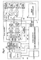
- FIG. 4 is a block diagram of the data storage apparatus in its entirety including the tape deck 11 already described in part with reference to Figure 1.
- the apparatus includes an interface unit 40 for interfacing the apparatus with a computer (not shown); a group processor 44 and a frame data processor 41 for processing main data and sub codes into and out of a Main Data Area fragment 27; a signal organiser 42 for composing/decomposing the signals for writing/reading a track and for appropriately switching the two heads HA, HB; and a system controller 43 for controlling the operation of the apparatus in response to commands received from a computer via the interface unit 40.
- the signal organiser 42 comprises an adaptive filter 62 for filtering data being read in a way which improves the read error rate.
- the data storage apparatus is arranged to respond to commands from a computer to load/unload a tape, to store a data record and other logical segmentation marks, to search for a selected record using the segmentation marks, and to read back the next record.
- the interface unit 40 is arranged to receive the commands from the computer and to manage the transfer of data records and logical data segmentation marks between the apparatus and computer. Upon receiving a command from the computer, the unit 40 passes it on to the system controller 43 which, in due course will send a response back to the computer via the unit 40 indicating compliance or otherwise with the original command. Once the apparatus has been set up by the system controller 43 in response to a command from the computer to store or read data, then the interface unit 40 will also control the passage of records and segmentation marks between the computer and the group processor 44.
- the group processor 44 is arranged to segment the main data provided to it in the form of data records into data packages each containing an amount of data corresponding to a fixed number (group) of frames (for example, twenty two). This segmentation is effected without regard to the logical organization of the data (that is, how it is divided into records). Information regarding the logical segmentation of the data (record divisions, file marks) is stored in an index which is generated by the processor 44 and which forms the last portion of data making up a group. The processor 44 also generates certain sub codes whose contents are group-dependent or concern the logical segmentation of data. To facilitate these tasks and the transfer of data to and from the processor 44, the latter is provided with a large buffer 74 which is arranged to hold several (for example, three) group's worth of data.
- the frame data processor 41 is transferred a frame at a time to the frame data processor 41.
- the frame data processor 41 there is no need for the frame data processor 41 to be aware of the grouping of frames as the group processor 44 could simply pass it a frame's worth of main data at a time together with the appropriate sub codes.
- the frame data processor 41 it is advantageous for the frame data processor 41 to be managed in terms of groups for receiving data from the processor 44 - in other words, during recording of data, the processor 41 is told by the group processor 44 when a group is ready for processing after which the processor 41 accesses the frames of the group autonomously from the buffer 74.
- the group processor 44 When data are being read from tape, the group processor 44 is arranged to receive main data from the processor 41 on a frame-by-frame basis, the data being written into the buffer 74 in such a manner as to build up a group. The group processor 44 can then access the group index to recover information on the logical organization (record structure, file marks) of the main data in the group. Using this information the group processor can pass the requested record or segmentation mark to the computer via the interface unit 40.
- each frame can be tagged with an in-group sequence number when the frame is written to tape.
- This in-group number can be provided as a sub code that, for example, is included at the head of the Main Data region of the first fragment in the Main Data Area of each track of a frame.
- the sub code is used on playback to determine where the related frame data are placed in the buffer 74 when passed to the group processor 44.
- the frame data processor 41 functionally comprises a Main-Data-Area (MDA) processor 65 and a sub code unit 67 with an associated electronic memory 68 for tape usage data (in practice, these functional elements may be constituted by a single microprocessor running appropriate processes under program control).
- MDA Main-Data-Area
- sub code unit 67 with an associated electronic memory 68 for tape usage data (in practice, these functional elements may be constituted by a single microprocessor running appropriate processes under program control).
- the sub code unit 67 is arranged to provide sub codes to the processor 65 as required during recording and to receive and distribute sub codes from the processor 65 during playback.
- sub codes may be generated/required by the group processor 44 or the system controller; the Area ID sub code is, for example, determined by/used by the controller 43.
- the sub codes may be permanently stored in the unit 67.
- frame-dependent sub codes such as absolute frame number, may conveniently be generated by the sub code unit 67 itself.
- these are read off from the system area of a tape upon first loading and stored by the unit 67 in the memory 68.
- the tape usage data held in the memory 68 are updated by the unit 67 as appropriate on the basis of inputs received from the processors 44, 65 and the controller 43; thus if a record is kept of the number of main data frames read/written (either directly or in terms of the number of groups read and written), then these data must be continually updated by the unit 67 as a result of inputs from the processor 65 (or possibly the processor 44 if groups are counted).
- the contents of the memory 68 are stored to tape within a log area of the tape system area, the latter being rewritten at the end of each session of usage.
- the multiple storage of the tape usage sub codes within the log area together with associated parity information, ensures a very high probability that the tape usage sub codes can be read back from the tape even in the presence of tape defects or other similar degradations.
- the MDA processor 65 is arranged to process a frame's worth of main data at a time together with the associated sub codes in the fragment Header regions. Thus during recording, the processor 65 receives a frame's worth of main data from the group processor 44 together with sub codes from the unit 67. On receiving the main data the processor 65 interleaves the data, and calculates error correcting codes and parity values, before assembling the resultant data and sub codes to output the Main-Data-Area fragments for the two tracks making up a frame. Before assembling the main data with the sub codes, scrambling (randomizing) of the data may be effected to ensure a consistent RF envelope independent of the data contents of a track signal.
- the processor 65 effects a reverse process on the two sets of Main-Data-Area fragments associated with the same frame. Unscrambled, error-corrected and de-interleaved main data are passed to the group processor 44 and sub codes are separated off and distributed by the unit 67 to the processor 44 or system controller 43 as required.
- the signal organizer 42 comprises a formatter/separator unit 53 which during recording (data writing) is arranged to assemble Main-Data-Area fragments provided by the frame data processor 41, to form the signal, including the sync bytes, to be recorded on each successive track.
- the necessary pre-amble patterns are also inserted into the track signals where necessary by the unit 53.
- Timing signals for coordinating the operation of the unit 53 with rotation of the heads HA, HB are provided by a timing generator 54 fed with drum position signals output by a pulse generator 50 responsive to head drum rotation and located in the tape deck 11.
- the track signals output on line 55 from the unit 53 are passed alternately to head HA and head HB via a head switch 56, respective head drive amplifiers 57, and record/playback switches 58 set to their record positions by the system controller 43.
- the head switch 56 is operated by appropriate timed signals from the timing generator 54.
- the timing generator 54 also provides timing signals ('read window timing signals') for triggering adaptive filtering as is known in the prior art. These timing signals are referenced to the drum position signals from the pulse generator 50 and, on average, will trigger adaptive filtering relatively late in the reading of a track. However, the enable signal from the timing generator 54 serves as a fallback in case the initial header(s) in a track are not detected for some reason.
- the track signals alternately generated by the heads HA and HB are fed via the record/playback switches 58 (now set by the system controller 43 to their playback positions), respective read amplifiers 59, a second head switch 60, and a clock recovery circuit 61 and the adaptive filter 62, to the input of the formatter/separator unit 53.
- the operation of the head switch 60 is controlled in the same manner as that of the head switch 56.
- the unit 53 now serves to generate signals indicating the timing of the Header regions (incorporating the sync bytes) of the data fragments in the track signals, to supply the timing signals to an ATF circuit 49 in the tape deck 11 and to the adaptive filter 62, and to pass the Main-Data-Area fragments to the frame data processor 41. Clock signals are also passed to the processor 41 from the clock recovery circuit 61.
- the tape deck 11 has four servos, namely a capstan servo 45 for controlling the rotation of the capstan 15, first and second reel servos 46, 47 for controlling rotation of the reels 13, 14 respectively, and a drum servo 48 for controlling the rotation of the head drum 12 ( Figure 1).
- Each servo includes a motor M and a rotation detector D both coupled to the element controlled by the servo.
- a detector 51 for sensing the ends of the tape beginning-of-media (BOM) and end-of-media (EOM); this detector 51 may be based for example on motor current sensing, as the motor current of whichever reel is being driven to wind in tape (dependent on the direction of tape travel) will increase significantly upon stalling of the motor at BOM/EOM.
- the operation of the tape deck 11 is controlled by a deck controller 52 which is connected to the servos 45 to 48 and to the BOM/EOM detector 51.
- the controller 52 is operable to cause the servos to advance the tape, (either at normal speed or at high speed) through any required distance. This control is effected either by energizing the servos for a time interval appropriate to the tape speed set, or by feedback of tape displacement information from one or more of the rotation detectors D associated with the servos.
- the deck controller 52 is itself governed by control signals issued by the system controller 43.
- the deck controller 52 is arranged to output to the controller 43 signals indicative of beginning of media (BOM) and end of media (EOM) being reached.
- the system controller 43 serves both to manage high-level interaction between the computer and storage apparatus and to coordinate the functioning of the other units of the storage apparatus in carrying out the basic operations of Load-Record-Search-Playback-Unload requested by the computer. In this latter respect, the controller 43 serves to coordinate the operation of the deck 11 with the data processing portion of the apparatus.
- the system controller can request the deck controller 52 to move the tape at the normal read/write speed (Normal) or to move the tape forwards or backwards at high speed, that is, Fast Forward (F.FWD) or Fast Rewind (F.RWD).
- Normal normal read/write speed
- F.FWD Fast Forward
- F.RWD Fast Rewind
- the ATF circuit 49 is operative during playback to compare the timing of the sync bytes in the selected Header regions in the track signal read from tape, with the drum position signal from the pulse generator 50, to provide an adjustment signal to the capstan servo 45 such that the heads HA, HB are properly aligned with the tracks recorded on the tape.
- reference signals for use in controlling track following by the heads HA and HB are constituted by these selected Header regions.
- Figure 5 illustrates part of two adjacent tracks on a tape medium 10.
- Header regions of fragments near the ends of two adjacent tracks 20 and 21 are indicated at 28 a and 28 b .
- the ideal paths for the relevant head along these tracks are shown by the dot-dash lines 80.
- the ATF circuit measures the time interval Int between the occurrence of the drum position signal, which is generated as one of the heads approaches the tape, and the detection of a reference signal comprising the sync bytes in the Header region 28a or 28b. When the heads are correctly following the paths 80, the time Int will match a preset reference value.
- the ATF circuit 49 can correct these tracking errors and keep the heads on the ideal paths 80.
- this time interval is measured for both the first and last Header regions in each track (i.e. in fragments 0 and 63), and the mean value of these two measurements is used to control the tape movement.
- adaptive filtering starts on commencement of reading main data in a track.
- Figure 5 shows the fragments near the ends of two adjacent tracks 20 and 21.
- the height of the recorded tracks in relation to the reference edge of the tape medium is typical for the height of the recorded tracks in relation to the reference edge of the tape medium to vary according to environmental factors eg. temperature, humidity and to vary for different tape drives.
- the track following circuits including the ATF circuit 49 are shown in more detail in Figure 6.
- the track signals from the heads HA and HB are fed via the amplifier stage 59 to the clock recovery circuit 61 and via the adaptive filter 62 to the formatter/separator unit 53.
- the circuit 61 which incorporates a phase-locked loop, provides the unit 53 with a clock signal, which is received together with the track signals by a decoder 90. Decoded signals are in turn supplied to a reference signal detector 91.
- this detector identifies fragment Headers in each track, and supplies a pulse at the time of detection of these reference signals, together with the value of the fragment ID, to an ATF controller 92 located in the ATF circuit 49. In addition, the pulses are sent to the timing generator 54.
- the timing generator 54 comprises a counter which starts counting on receipt of the drum position signal from the pulse generator 50. Thereafter the timing generator 54 supplies a pulse to the adaptive filter 62 to enable adaptive filtering on the first to occur of:
- adaptive filtering is initiated on either the detection of the first header by the reference signal detector 91 or the read window timing signal from the timing generator 54.
- the timing generator 54 After elapse of a predetermined time after arrival of the drum position signal, the timing generator 54 supplies another read window timing signal, this time to disable adaptive filtering. In this way, near the end of a track being read, the adaptive filter is deactivated. The counter in the timing generator 54 is then reset ready for the next track.
- An interval timer 94 in the ATF circuit 49 receives the drum position signal from the pulse generator 50 associated with the drum 12, and measures time intervals starting with each position signal until it is reset by the ATF controller 92.
- This controller is coupled to the interval timer to latch its time measurement upon receipt of each reference signal detection pulse, and supplies a control signal to the capstan servo 45 in dependence upon comparison of the latched time measurements with the reference value.
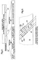
- Figure 7 is a timing diagram.
- the drum position signal generated by the pulse generator 50 is indicated at D.
- the height of tracks with reference to the edge of the tape medium can vary.
- Track 1 and Track 2 in Figure 7 indicate the extent of the possible timing difference in the start of a track due to differing track heights.
- Track 1 is relatively close to the reference edge of the tape medium in comparison to Track 2.
- Track 3 indicates a recorded track somewhere inbetween the extremes of Track 1 and Track 2 and shall be taken as a nominal track for the purpose of illustrating the advantages of the present invention.
- a nominal track is one which is being read by the tape drive which wrote it and under approximately the same environmental conditions under which it was written.
- Tracks 1,2 and 3 the portions at the start and end of the tracks with spectral characteristics which are unsuitable for adaptive filtering are shown shaded.
- the clear portions of the tracks indicate main data suitable for adaptive filtering.
- An asterisk in Tracks 1,2 and 3 indicates when the header in the first data fragment in the track occurs.
- adaptive filtering is initiated by a read window timing signal, indicated at RW, a predetermined time after the drum position signal D.
- the predetermined time is chosen conservatively so as to account for possible variations in track height. As indicated in Figure 7, this coincides with the start of main data in Track 2 and results, on average, in adaptive filtering being triggered relatively late in the reading of a track and this is detrimental to error rate performance. However, this is better than starting adaptive filtering too early in the track when the signals from the read head have undesirable spectral characteristics.
- Adaptive filtering is also deactivated by the read window timing signal RW near the end of the track being read.
- the adapt-disable signal coincides with the end of main data in Track 1. The moment at which adaptive filtering is disabled is, in general, less important than the timing of the start of adaptive filtering.
- adaptive filtering is triggered on detection of the header of the first fragment of data in a sampled track (Track 3 in Figure 7) which results, on average, in adaptive filtering being triggered earlier in the reading of a track, but not before the signals from the read head have suitable spectral characteristics.
- the window for adaptive filtering according to the present invention is indicated at AW.
- the invention may be used with a reference signal comprising any format of fragment or block header instead of the one shown in Figure 3, or indeed comprising any recognizable bit pattern which is known or arranged to occur at a predictable position or positions along a track.
Landscapes
- Engineering & Computer Science (AREA)
- Signal Processing (AREA)
- Signal Processing For Digital Recording And Reproducing (AREA)
Claims (5)
- Magnetbandspeichervorrichtung zum Lesen und Schreiben von Daten von einem und auf ein Speichermedium, bei der die Daten in Spuren auf das Medium geschrieben werden, wobei jede Spur Hauptdaten und Nebeninformationen, die ein vorbestimmtes Auslösesignalmuster aufweisen, aufweist, wobei die Vorrichtung folgende Merkmale aufweist:eine Einrichtung zum Erfassen des vorbestimmten Auslösesignalmusters;ein adaptives Filter für von dem Medium gelesene Signale;und eine Einrichtung zum Auslösen eines adaptiven Filterns, durch das adaptive Filter, nur der Hauptdaten, nach den Nebeninformationen, einer Spur von Daten bei der Erfassung des vorbestimmten Auslösesignalmusters in dieser Spur.
- Vorrichtung gemäß Anspruch 1, bei der jede Spur Datenfragmente aufweist, die jeweils einen Kopfblock aufweisen, der Nebeninformationen enthält, wobei mindestens ein Kopfblock in einem anfänglichen Datenfragment in der Spur das vorbestimmte Auslösesignalmuster aufweist.
- Vorrichtung gemäß Anspruch 2, bei der zumindest der Kopfblock in dem ersten Datenfragment in der Spur das vorbestimmte Auslösesignalmuster aufweist.
- Vorrichtung gemäß einem der vorhergehenden Ansprüche, bei der das vorbestimmte Auslösesignalmuster auch zum Steuern der Bewegung des Mediums verwendet wird.
- Ein Verfahren zum Auslösen eines adaptiven Filterns bei einer Vorrichtung zum Lesen und Schreiben von Daten auf ein Speichermedium in Form von Spuren, wobei jede Spur Hauptdaten und Nebeninformationen aufweist, wobei das Verfahren folgende Schritte aufweist:Überwachen bezüglich des Vorliegens eines vorbestimmten Auslösesignalmusters während des Lesens von Daten von einer Spur, und Auslösen des adaptiven Filterns der Hauptdaten in der Spur, wenn das vorbestimmte Auslösesignalmuster erfaßt wird.
Priority Applications (4)
| Application Number | Priority Date | Filing Date | Title |
|---|---|---|---|
| DE69617422T DE69617422T2 (de) | 1996-09-24 | 1996-09-24 | Datenspeicher |
| EP96306933A EP0831477B1 (de) | 1996-09-24 | 1996-09-24 | Datenspeicher |
| JP9245088A JPH10106164A (ja) | 1996-09-24 | 1997-09-10 | データ記憶装置 |
| US08/936,843 US6198588B1 (en) | 1996-09-24 | 1997-09-23 | Data Storage |
Applications Claiming Priority (1)
| Application Number | Priority Date | Filing Date | Title |
|---|---|---|---|
| EP96306933A EP0831477B1 (de) | 1996-09-24 | 1996-09-24 | Datenspeicher |
Publications (2)
| Publication Number | Publication Date |
|---|---|
| EP0831477A1 EP0831477A1 (de) | 1998-03-25 |
| EP0831477B1 true EP0831477B1 (de) | 2001-11-28 |
Family
ID=8225091
Family Applications (1)
| Application Number | Title | Priority Date | Filing Date |
|---|---|---|---|
| EP96306933A Expired - Lifetime EP0831477B1 (de) | 1996-09-24 | 1996-09-24 | Datenspeicher |
Country Status (4)
| Country | Link |
|---|---|
| US (1) | US6198588B1 (de) |
| EP (1) | EP0831477B1 (de) |
| JP (1) | JPH10106164A (de) |
| DE (1) | DE69617422T2 (de) |
Cited By (1)
| Publication number | Priority date | Publication date | Assignee | Title |
|---|---|---|---|---|
| WO2008029532A1 (fr) * | 2006-09-05 | 2008-03-13 | Panasonic Corporation | Appareil de traitement de signaux de reproduction |
Families Citing this family (2)
| Publication number | Priority date | Publication date | Assignee | Title |
|---|---|---|---|---|
| DE69617422T2 (de) | 1996-09-24 | 2002-05-16 | Hewlett Packard Co | Datenspeicher |
| US9195860B1 (en) | 2014-01-10 | 2015-11-24 | Seagate Technology Llc | Adaptively combining waveforms |
Citations (2)
| Publication number | Priority date | Publication date | Assignee | Title |
|---|---|---|---|---|
| EP0527017A1 (de) * | 1991-08-03 | 1993-02-10 | Sony Corporation | Magnetisches Wiedergabegerät |
| JPH08194906A (ja) * | 1995-01-20 | 1996-07-30 | Fujitsu Ltd | ディスク装置 |
Family Cites Families (4)
| Publication number | Priority date | Publication date | Assignee | Title |
|---|---|---|---|---|
| JP3013535B2 (ja) * | 1991-08-03 | 2000-02-28 | ソニー株式会社 | 磁気再生装置 |
| US5150379A (en) * | 1991-09-27 | 1992-09-22 | Hewlett-Packard Company | Signal processing system for adaptive equalization |
| DE69230969D1 (de) * | 1992-07-10 | 2000-05-31 | Ibm | Verfahren und Einrichtung zur adaptiven Entzerrung |
| DE69617422T2 (de) | 1996-09-24 | 2002-05-16 | Hewlett Packard Co | Datenspeicher |
-
1996
- 1996-09-24 DE DE69617422T patent/DE69617422T2/de not_active Expired - Lifetime
- 1996-09-24 EP EP96306933A patent/EP0831477B1/de not_active Expired - Lifetime
-
1997
- 1997-09-10 JP JP9245088A patent/JPH10106164A/ja active Pending
- 1997-09-23 US US08/936,843 patent/US6198588B1/en not_active Expired - Lifetime
Patent Citations (3)
| Publication number | Priority date | Publication date | Assignee | Title |
|---|---|---|---|---|
| EP0527017A1 (de) * | 1991-08-03 | 1993-02-10 | Sony Corporation | Magnetisches Wiedergabegerät |
| JPH08194906A (ja) * | 1995-01-20 | 1996-07-30 | Fujitsu Ltd | ディスク装置 |
| US5623474A (en) * | 1995-01-20 | 1997-04-22 | Fujitsu Limited | Disk apparatus having automatic adjustment of adaptive filter equalization parameter using training pattern |
Cited By (1)
| Publication number | Priority date | Publication date | Assignee | Title |
|---|---|---|---|---|
| WO2008029532A1 (fr) * | 2006-09-05 | 2008-03-13 | Panasonic Corporation | Appareil de traitement de signaux de reproduction |
Also Published As
| Publication number | Publication date |
|---|---|
| US6198588B1 (en) | 2001-03-06 |
| JPH10106164A (ja) | 1998-04-24 |
| EP0831477A1 (de) | 1998-03-25 |
| DE69617422T2 (de) | 2002-05-16 |
| DE69617422D1 (de) | 2002-01-10 |
Similar Documents
| Publication | Publication Date | Title |
|---|---|---|
| US5057950A (en) | Data storage method | |
| EP0272130B1 (de) | Datenaufzeichnung | |
| US5369532A (en) | Method and apparatus for managing data on rewritable media to define read/write operational status | |
| US6898036B2 (en) | System and method for recovery from writing errors during data storage | |
| US5029022A (en) | Method of storing data on recording tape | |
| US6229659B1 (en) | Methods and apparatus for storing data and auxiliary information | |
| EP1166261A2 (de) | Fehlerkorrektur für schrägspur-bandlaufwerk durch benützung der spurprofilabbildung | |
| US5969898A (en) | Method and system for reading data that is unreadable by a tape drive | |
| JP4398589B2 (ja) | データ記憶装置およびその方法 | |
| US7813069B2 (en) | Method and apparatus for controlling motion of storage media | |
| EP0831477B1 (de) | Datenspeicher | |
| EP0671735B1 (de) | Verfahren und Gerät für die Bewegungssteuerung von Aufzeichnungsmedien | |
| EP0329265B1 (de) | Datenspeicherungsverfahren | |
| EP0831482A2 (de) | Verfahren und Gerätzur Datenspeicherung | |
| US6038092A (en) | System for reading data from a distorted magnetic tape media | |
| EP0831476A1 (de) | Verfahren und Gerät zur Steuerung der Funktion der Leseschaltung eines Bandlaufwerkes | |
| US6715033B2 (en) | Method of and apparatus for tracking appended data on storage medium | |
| EP0831481A1 (de) | Verfahren und Gerät zur Datenspeicherung | |
| US7911727B2 (en) | Controlling motion of storage media | |
| JPH03288370A (ja) | 回転ヘッド式データレコーダの記録方法 |
Legal Events
| Date | Code | Title | Description |
|---|---|---|---|
| PUAI | Public reference made under article 153(3) epc to a published international application that has entered the european phase |
Free format text: ORIGINAL CODE: 0009012 |
|
| AK | Designated contracting states |
Kind code of ref document: A1 Designated state(s): DE FR GB |
|
| 17P | Request for examination filed |
Effective date: 19980921 |
|
| AKX | Designation fees paid |
Free format text: DE FR GB |
|
| RBV | Designated contracting states (corrected) |
Designated state(s): DE FR GB |
|
| 17Q | First examination report despatched |
Effective date: 19990730 |
|
| GRAG | Despatch of communication of intention to grant |
Free format text: ORIGINAL CODE: EPIDOS AGRA |
|
| GRAG | Despatch of communication of intention to grant |
Free format text: ORIGINAL CODE: EPIDOS AGRA |
|
| RAP1 | Party data changed (applicant data changed or rights of an application transferred) |
Owner name: HEWLETT-PACKARD COMPANY, A DELAWARE CORPORATION |
|
| GRAG | Despatch of communication of intention to grant |
Free format text: ORIGINAL CODE: EPIDOS AGRA |
|
| GRAH | Despatch of communication of intention to grant a patent |
Free format text: ORIGINAL CODE: EPIDOS IGRA |
|
| GRAH | Despatch of communication of intention to grant a patent |
Free format text: ORIGINAL CODE: EPIDOS IGRA |
|
| GRAA | (expected) grant |
Free format text: ORIGINAL CODE: 0009210 |
|
| AK | Designated contracting states |
Kind code of ref document: B1 Designated state(s): DE FR GB |
|
| REG | Reference to a national code |
Ref country code: GB Ref legal event code: IF02 |
|
| REF | Corresponds to: |
Ref document number: 69617422 Country of ref document: DE Date of ref document: 20020110 |
|
| ET | Fr: translation filed | ||
| PLBE | No opposition filed within time limit |
Free format text: ORIGINAL CODE: 0009261 |
|
| STAA | Information on the status of an ep patent application or granted ep patent |
Free format text: STATUS: NO OPPOSITION FILED WITHIN TIME LIMIT |
|
| 26N | No opposition filed | ||
| PGFP | Annual fee paid to national office [announced via postgrant information from national office to epo] |
Ref country code: GB Payment date: 20090929 Year of fee payment: 14 |
|
| PGFP | Annual fee paid to national office [announced via postgrant information from national office to epo] |
Ref country code: DE Payment date: 20090929 Year of fee payment: 14 |
|
| GBPC | Gb: european patent ceased through non-payment of renewal fee |
Effective date: 20100924 |
|
| REG | Reference to a national code |
Ref country code: FR Ref legal event code: ST Effective date: 20110531 |
|
| REG | Reference to a national code |
Ref country code: DE Ref legal event code: R119 Ref document number: 69617422 Country of ref document: DE Effective date: 20110401 |
|
| PG25 | Lapsed in a contracting state [announced via postgrant information from national office to epo] |
Ref country code: FR Free format text: LAPSE BECAUSE OF NON-PAYMENT OF DUE FEES Effective date: 20100930 Ref country code: DE Free format text: LAPSE BECAUSE OF NON-PAYMENT OF DUE FEES Effective date: 20110401 |
|
| PG25 | Lapsed in a contracting state [announced via postgrant information from national office to epo] |
Ref country code: GB Free format text: LAPSE BECAUSE OF NON-PAYMENT OF DUE FEES Effective date: 20100924 |
|
| PGFP | Annual fee paid to national office [announced via postgrant information from national office to epo] |
Ref country code: FR Payment date: 20091006 Year of fee payment: 14 |