EP0830894A1 - Mixer-reactor and process to perform reactions, especially phosgenation of primary amines - Google Patents
Mixer-reactor and process to perform reactions, especially phosgenation of primary amines Download PDFInfo
- Publication number
- EP0830894A1 EP0830894A1 EP97115513A EP97115513A EP0830894A1 EP 0830894 A1 EP0830894 A1 EP 0830894A1 EP 97115513 A EP97115513 A EP 97115513A EP 97115513 A EP97115513 A EP 97115513A EP 0830894 A1 EP0830894 A1 EP 0830894A1
- Authority
- EP
- European Patent Office
- Prior art keywords
- mixing chamber
- mixer
- nozzles
- axis
- substance
- Prior art date
- Legal status (The legal status is an assumption and is not a legal conclusion. Google has not performed a legal analysis and makes no representation as to the accuracy of the status listed.)
- Granted
Links
Images


Classifications
-
- B—PERFORMING OPERATIONS; TRANSPORTING
- B01—PHYSICAL OR CHEMICAL PROCESSES OR APPARATUS IN GENERAL
- B01F—MIXING, e.g. DISSOLVING, EMULSIFYING OR DISPERSING
- B01F33/00—Other mixers; Mixing plants; Combinations of mixers
- B01F33/80—Mixing plants; Combinations of mixers
- B01F33/81—Combinations of similar mixers, e.g. with rotary stirring devices in two or more receptacles
-
- B—PERFORMING OPERATIONS; TRANSPORTING
- B01—PHYSICAL OR CHEMICAL PROCESSES OR APPARATUS IN GENERAL
- B01J—CHEMICAL OR PHYSICAL PROCESSES, e.g. CATALYSIS OR COLLOID CHEMISTRY; THEIR RELEVANT APPARATUS
- B01J19/00—Chemical, physical or physico-chemical processes in general; Their relevant apparatus
- B01J19/18—Stationary reactors having moving elements inside
-
- B—PERFORMING OPERATIONS; TRANSPORTING
- B01—PHYSICAL OR CHEMICAL PROCESSES OR APPARATUS IN GENERAL
- B01F—MIXING, e.g. DISSOLVING, EMULSIFYING OR DISPERSING
- B01F27/00—Mixers with rotary stirring devices in fixed receptacles; Kneaders
- B01F27/27—Mixers with stator-rotor systems, e.g. with intermeshing teeth or cylinders or having orifices
- B01F27/271—Mixers with stator-rotor systems, e.g. with intermeshing teeth or cylinders or having orifices with means for moving the materials to be mixed radially between the surfaces of the rotor and the stator
- B01F27/2711—Mixers with stator-rotor systems, e.g. with intermeshing teeth or cylinders or having orifices with means for moving the materials to be mixed radially between the surfaces of the rotor and the stator provided with intermeshing elements
-
- B—PERFORMING OPERATIONS; TRANSPORTING
- B01—PHYSICAL OR CHEMICAL PROCESSES OR APPARATUS IN GENERAL
- B01F—MIXING, e.g. DISSOLVING, EMULSIFYING OR DISPERSING
- B01F33/00—Other mixers; Mixing plants; Combinations of mixers
- B01F33/80—Mixing plants; Combinations of mixers
- B01F33/81—Combinations of similar mixers, e.g. with rotary stirring devices in two or more receptacles
- B01F33/811—Combinations of similar mixers, e.g. with rotary stirring devices in two or more receptacles in two or more consecutive, i.e. successive, mixing receptacles or being consecutively arranged
-
- B—PERFORMING OPERATIONS; TRANSPORTING
- B01—PHYSICAL OR CHEMICAL PROCESSES OR APPARATUS IN GENERAL
- B01J—CHEMICAL OR PHYSICAL PROCESSES, e.g. CATALYSIS OR COLLOID CHEMISTRY; THEIR RELEVANT APPARATUS
- B01J19/00—Chemical, physical or physico-chemical processes in general; Their relevant apparatus
- B01J19/18—Stationary reactors having moving elements inside
- B01J19/1806—Stationary reactors having moving elements inside resulting in a turbulent flow of the reactants, such as in centrifugal-type reactors, or having a high Reynolds-number
-
- B—PERFORMING OPERATIONS; TRANSPORTING
- B01—PHYSICAL OR CHEMICAL PROCESSES OR APPARATUS IN GENERAL
- B01J—CHEMICAL OR PHYSICAL PROCESSES, e.g. CATALYSIS OR COLLOID CHEMISTRY; THEIR RELEVANT APPARATUS
- B01J19/00—Chemical, physical or physico-chemical processes in general; Their relevant apparatus
- B01J19/18—Stationary reactors having moving elements inside
- B01J19/1887—Stationary reactors having moving elements inside forming a thin film
-
- B—PERFORMING OPERATIONS; TRANSPORTING
- B01—PHYSICAL OR CHEMICAL PROCESSES OR APPARATUS IN GENERAL
- B01J—CHEMICAL OR PHYSICAL PROCESSES, e.g. CATALYSIS OR COLLOID CHEMISTRY; THEIR RELEVANT APPARATUS
- B01J19/00—Chemical, physical or physico-chemical processes in general; Their relevant apparatus
- B01J19/26—Nozzle-type reactors, i.e. the distribution of the initial reactants within the reactor is effected by their introduction or injection through nozzles
-
- B—PERFORMING OPERATIONS; TRANSPORTING
- B01—PHYSICAL OR CHEMICAL PROCESSES OR APPARATUS IN GENERAL
- B01F—MIXING, e.g. DISSOLVING, EMULSIFYING OR DISPERSING
- B01F25/00—Flow mixers; Mixers for falling materials, e.g. solid particles
- B01F2025/91—Direction of flow or arrangement of feed and discharge openings
- B01F2025/912—Radial flow
-
- B—PERFORMING OPERATIONS; TRANSPORTING
- B01—PHYSICAL OR CHEMICAL PROCESSES OR APPARATUS IN GENERAL
- B01J—CHEMICAL OR PHYSICAL PROCESSES, e.g. CATALYSIS OR COLLOID CHEMISTRY; THEIR RELEVANT APPARATUS
- B01J2219/00—Chemical, physical or physico-chemical processes in general; Their relevant apparatus
- B01J2219/18—Details relating to the spatial orientation of the reactor
- B01J2219/182—Details relating to the spatial orientation of the reactor horizontal
Definitions
- the invention relates to a mixer reactor for mixing and carrying out or initiation of a reaction of at least two flowable substances, in particular for the production of mono- or polyisocyanates by reacting the the mono- or polyamines corresponding to the mono- or polyisocyanates with in organic solvent dissolved phosgene.
- a mixer reactor which consists of a substantially rotationally symmetrical housing consists, the housing being an essentially rotationally symmetrical mixing chamber with separate inlets for the at least two substances and one outlet has, the inlet for the at least first substance in the axis of Mixing chamber is provided and the inlet for the at least second substance in Form a plurality of rotationally symmetrical to the mixing chamber axis Nozzles is formed; see e.g. US-A 4 851 571, US-A 4 915 509 and US-A 5,117,048.
- the quality of products manufactured in such apparatus depends very much on the quality and speed of mixing the at least two flowable Fabrics.
- the injection of uniform mass flows plays a particular role here through each of the nozzles into the mixing chamber.
- a disadvantage of the known mixer reactors is that it is inside the nozzles Over time, caking up to blockages occurs, so that the injection same mass flows through all nozzles is disturbed. At least on that The second substance is therefore high requirements regarding freedom of solids or reactable foreign substances. An increased risk of constipation occurs especially when the second substance is in a solvent or suspending medium is dissolved or suspended, the solution or suspending medium from separated from the product and used again. To reduce the tendency to cake and clogging, it is necessary to carry out a high level of cleaning for the reusable solution or suspension medium float. Side reactions with the first substance can also cause caking occur on the mixer inlet side of the nozzles.
- the invention relates to a mixer reactor for mixing and carrying out or initiation of a reaction of at least two flowable substances, which consists of an essentially rotationally symmetrical housing, the one Mixing chamber with separate inlets for the at least two substances with one Contains outlet, the inlet for the at least first substance in the axis of Mixing chamber is provided and the inlet for the at least second substance in Form a variety of rotationally symmetrical to the axis of the mixing chamber arranged nozzles is formed, with the characteristic that each nozzle one in Direction of the nozzle axis is assigned to displaceable bolts.
- the bolts are preferably located upstream of the mixing chamber Distribution chamber into which the at least second substance is introduced and within which is distributed over the plurality of nozzles.
- the nozzles are pierced by axially displacing the bolts and caking or blockages removed.
- the mixer downtime according to the invention accordingly reduces the production downtimes reduced to a few seconds for cleaning the nozzles.
- the nozzles are usually in the form of concentric about the mixing chamber axis arranged through holes through the partition between the distribution chamber and mixing chamber formed.
- the number of nozzles can be 6 to 32.
- the diameter of the nozzles is typically between 1 and 10 mm.
- the longitudinal expansion and the minimum possible stroke of the bolts exceeds the longitudinal expansion of the nozzle bores.
- the pin is released the nozzle entrance free.
- the end face of the bolt during the Operate such a distance from the inlet of the nozzle that the inlet flow of the flowable substance is throttled into the nozzle.
- the turbulence it creates reduces the risk of caking in the nozzle.
- the front End of the bolt should be designed so that a rotating inlet flow is produced.
- the mixing chamber can be designed in the form of a Venturi tube, the Nozzles for introducing the at least second substance essentially radially open into the mixing chamber at the narrowest point of the Venturi tube.
- a such a mixing chamber is disclosed in US-A 5 117 048.
- the mixing chamber is in shape a centrifugal mixer with rotor and stator mixing elements.
- Mixer reactors are known for example from US-A 4 915 509 and GB-A 2 169 814 known. This can be done on the rotor axis following the actual mixing chamber an impeller can be provided, which the removal of the mixed and possibly reacted current supported.
- the nozzles are preferably on the end face of the mixer arranged parallel to the mixer axis.
- the bolts are preferably attached to a common support ring, which has a through the Housing of the distribution chamber is passed axis.
- the implementation is preferably gas-tight encapsulated by the axis, for example by a welded bellows.
- the mixer reactor according to the invention is particularly suitable as a pre-phosgenation reactor for the production of isocyanates. It will be the first at least Substance phosgene dissolved in an organic solvent and as at least second substance optionally primary amine dissolved in a solvent. With regard to the starting materials and reaction conditions in detail to US-A-4,851,571, US-A-5,117,048 and WO 96/16 028 Referred. Isocyanate can also be used as a solvent for the phosgene are used (WO 96/16 028).
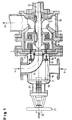
- the mixer-reactor shown in FIG. 1 consists of a Housing 1, which has a mixing chamber 2 and a distribution chamber 3. Of the at least first material flow 4 is laterally via a in the distribution chamber wall entering bent tube 5 axially introduced into the mixing chamber 2.
- the least second stream 6 is introduced into the distribution chamber 3 and passes a large number of parallel nozzle bores concentric to the axis of the mixer reactor 7 into the mixing chamber 2.
- the mixing chamber 2 contains an axis 10 driven rotor elements 8 and stator elements connected to the housing 9.
- an impeller 11 is provided, which mixes via the annular channel 12 promotes in the outlet pipe 13.
- each nozzle 7 is assigned Bolts 15 are provided which are fastened on a support ring 17.
- the support ring 17 is connected via spacers 18 to a plate 19 which is connected via an axis 22 is displaceable in the axial direction by means of a handwheel.
- Implementation of the axis 22 through the distribution chamber wall is encapsulated gas-tight by means of bellows 20.
- Fig. 2 shows an enlarged view of the detail A from Fig. 1, wherein the Distance of the end face of the bolt 15 from the inlet into the nozzle 7 is selected that a throttling of the inlet flow, which is indicated by arrows 23, he follows.
- FIG. 3 shows an alternatively enlarged illustration of the detail A from FIG. 1, wherein the end face of the bolt 15 is designed such that a rotating inlet flow is produced.
- Fig. 4 shows a bolt 15 with a cross section of the inlet flow in the nozzle 7 narrowing attachment 24.
- FIG. 5 shows the axial section through a mixer reactor according to the invention, wherein the mixing chamber 2 is designed as a Venturi tube.
- the distribution chamber 3 is arranged concentrically around the mixing chamber 2.
- the nozzles 7 open radially into the mixing chamber 2. Accordingly, the bolts 15 are individually over bellows seals 20 radially displaceable. Otherwise, the representation in Fig. 1st corresponding elements denoted by the same reference numerals.
Abstract
Description
Die Erfindung betrifft einen Mischer-Reaktor zur Vermischung und Durchführung bzw. Einleitung einer Reaktion von mindestens zwei fließfähigen Stoffen, insbesondere zur Herstellung von Mono- oder Polyisocyanaten durch Umsetzung der den Mono- oder Polyisocyanaten entsprechenden Mono- oder Polyamine mit in organischem Lösungsmittel gelöstem Phosgen.The invention relates to a mixer reactor for mixing and carrying out or initiation of a reaction of at least two flowable substances, in particular for the production of mono- or polyisocyanates by reacting the the mono- or polyamines corresponding to the mono- or polyisocyanates with in organic solvent dissolved phosgene.
Es ist bekannt, solche schnell einsetzenden Reaktionen in einem Mischer-Reaktor durchzuführen, der aus einem im wesentlichen rotationssymmetrischen Gehäuse besteht, wobei das Gehäuse eine im wesentlichen rotationssymmetrische Mischkammer mit getrennten Einlässen für die mindestens zwei Stoffe und einen Auslaß aufweist, wobei der Einlaß für den mindestens ersten Stoff in der Achse der Mischkammer vorgesehen ist und der Einlaß für den mindestens zweiten Stoff in Form einer Vielzahl von rotationssymmetrisch zur Mischkammerachse angeordneten Düsen ausgebildet ist; siehe z.B. US-A 4 851 571, US-A 4 915 509 und US-A 5 117 048.It is known such rapid reactions in a mixer reactor perform, which consists of a substantially rotationally symmetrical housing consists, the housing being an essentially rotationally symmetrical mixing chamber with separate inlets for the at least two substances and one outlet has, the inlet for the at least first substance in the axis of Mixing chamber is provided and the inlet for the at least second substance in Form a plurality of rotationally symmetrical to the mixing chamber axis Nozzles is formed; see e.g. US-A 4 851 571, US-A 4 915 509 and US-A 5,117,048.
Die Qualität von in derartigen Apparaten hergestellten Produkten hängt sehr stark von der Güte und Geschwindigkeit der Vermischung der mindestens zwei fließfähigen Stoffe ab. Dabei spielt insbesondere die Eindüsung gleichmäßiger Masseströme durch jede der Düsen in die Mischkammer eine entscheidende Rolle.The quality of products manufactured in such apparatus depends very much on the quality and speed of mixing the at least two flowable Fabrics. The injection of uniform mass flows plays a particular role here through each of the nozzles into the mixing chamber.
Nachteilig an den bekannten Mischer-Reaktoren ist, daß es innerhalb der Düsen im Laufe der Zeit zu Anbackungen bis hin zu Verstopfungen kommt, so daß die Eindüsung gleicher Massenströme durch alle Düsen gestört wird. Zumindest an den zweiten Stoff sind daher hohe Anforderungen bezüglich Freiheit an Feststoffen bzw. reagierbaren Fremdstoffen zu stellen. Ein erhöhtes Verstopfungsrisiko tritt insbesondere dann auf, wenn der zweite Stoff in einem Lösungs- bzw. Suspendiermedium gelöst oder suspendiert wird, das Lösungs- bzw. Suspendiermedium von dem Produkt abgetrennt und wieder verwendet wird. Zur Reduktion der Anbackungs- und Verstopfungsneigung ist es erforderlich, einen hohen Reinigungsaufwand für das wieder zu verwendende Lösungs- bzw. Suspendiermedium zu treiben. Durch Nebenreaktionen mit dem ersten Stoff können ferner Anbackungen auf der Mischer-Eingangsseite der Düsen auftreten. Im Falle auftretender Anbackungen und/oder Verstopfungen muß der kontinuierliche Prozeß unterbrochen werden, der Mischer-Reaktor auseinandergebaut und gereinigt werden. Dies bedingt erhebliche Stillstandszeiten. Bei Einsatz gefährlicher Stoffe, wie im Falle von Phosgen, sind bei der Demontage des Mischer-Reaktors aufwendige arbeitshygienische Maßnahmen erforderlich, wie intensives Spülen des Reäktors vor der Demontage, Schutzkleidung, Absaugen der Atmosphäre, Atemschutzgerät, usw.A disadvantage of the known mixer reactors is that it is inside the nozzles Over time, caking up to blockages occurs, so that the injection same mass flows through all nozzles is disturbed. At least on that The second substance is therefore high requirements regarding freedom of solids or reactable foreign substances. An increased risk of constipation occurs especially when the second substance is in a solvent or suspending medium is dissolved or suspended, the solution or suspending medium from separated from the product and used again. To reduce the tendency to cake and clogging, it is necessary to carry out a high level of cleaning for the reusable solution or suspension medium float. Side reactions with the first substance can also cause caking occur on the mixer inlet side of the nozzles. In the event of caking and / or blockages the continuous process must be interrupted disassembled and cleaned the mixer-reactor. This requires considerable downtimes. When using dangerous substances, as in the case of phosgene, are complex hygienic work when dismantling the mixer reactor Measures required, such as intensive rinsing of the reactor before Disassembly, protective clothing, suction of the atmosphere, breathing apparatus, etc.
Gegenstand der Erfindung ist ein Mischer-Reaktor zur Vermischung und Durchführung bzw. Einleitung einer Reaktion von mindestens zwei fließfähigen Stoffen, der aus einem im wesentlichen rotationssymmetrischem Gehäuse besteht, das eine Mischkammer mit getrennten Einlässen für die mindestens zwei Stoffe mit einem Auslaß enthält, wobei der Einlaß für den mindestens ersten Stoff in der Achse der Mischkammer vorgesehen ist und der Einlaß für den mindestens zweiten Stoff in Form einer Vielzahl von rotationssymmetrisch zur Achse der Mischkammer angeordneten Düsen ausgebildet ist, mit dem Kennzeichen, daß jeder Düse ein in Richtung der Düsenachse verschiebbarer Bolzen zugeordnet ist.The invention relates to a mixer reactor for mixing and carrying out or initiation of a reaction of at least two flowable substances, which consists of an essentially rotationally symmetrical housing, the one Mixing chamber with separate inlets for the at least two substances with one Contains outlet, the inlet for the at least first substance in the axis of Mixing chamber is provided and the inlet for the at least second substance in Form a variety of rotationally symmetrical to the axis of the mixing chamber arranged nozzles is formed, with the characteristic that each nozzle one in Direction of the nozzle axis is assigned to displaceable bolts.
Die Bolzen sind vorzugsweise innerhalb einer der Mischkammer vorgeordneten Verteilkammer, in die der mindestens zweite Stoff eingeleitet wird und innerhalb der dieser auf die Vielzahl von Düsen verteilt wird, angeordnet.The bolts are preferably located upstream of the mixing chamber Distribution chamber into which the at least second substance is introduced and within which is distributed over the plurality of nozzles.
Im Falle von sich ausbildenden Anbackungen und/oder Verstopfungen der Düsen, was durch einen Druckanstieg in der Zuleitung für den mindestens zweiten Stoff feststellbar ist, werden die Düsen durch axiale Verschiebung der Bolzen durchstoßen und Anbackungen bzw. Verstopfungen entfernt.In the event of caking and / or clogging of the nozzles, what by a pressure increase in the supply line for the at least second substance Ascertainable, the nozzles are pierced by axially displacing the bolts and caking or blockages removed.
Durch den erfindungsgemäßen Mischer-Reaktor werden demgemäß die Produktionsausfallzeiten für die Reinigung der Düsen auf wenige Sekunden reduziert.The mixer downtime according to the invention accordingly reduces the production downtimes reduced to a few seconds for cleaning the nozzles.
Üblicherweise sind die Düsen in Form von konzentrisch um die Mischkammerachse angeordneten Durchgangsbohrungen durch die Trennwand zwischen Verteilkammer und Mischkammer ausgebildet. Die Anzahl der Düsen kann 6 bis 32 betragen. Der Durchmesser der Düsen beträgt typischerweise zwischen 1 und 10 mm. Die Längsausdehnung und der minimal mögliche Hub der Bolzen übersteigt die Längsausdehnung der Düsenbohrungen.The nozzles are usually in the form of concentric about the mixing chamber axis arranged through holes through the partition between the distribution chamber and mixing chamber formed. The number of nozzles can be 6 to 32. The diameter of the nozzles is typically between 1 and 10 mm. The longitudinal expansion and the minimum possible stroke of the bolts exceeds the longitudinal expansion of the nozzle bores.
Während des Betriebes des erfindungsgemäßen Mischer-Reaktors gibt der Bolzen den Düseneingang frei. Vorzugsweise hat die Stirnfläche des Bolzens während des Betriebes einen solchen Abstand vom Eingang der Düse, daß die Eintrittsströmung des fließfähigen Stoffes in die Düse gedrosselt wird. Die dadurch erzeugte Turbulenz reduziert das Risiko der Ausbildung von Anbackungen in der Düse.During the operation of the mixer reactor according to the invention, the pin is released the nozzle entrance free. Preferably, the end face of the bolt during the Operate such a distance from the inlet of the nozzle that the inlet flow of the flowable substance is throttled into the nozzle. The turbulence it creates reduces the risk of caking in the nozzle.
Nach einer weiter bevorzugten Ausführungsform der Erfindung kann das stirnseitige Ende des Bolzens so gestaltet sein, daß eine rotierende Einlaufströmung erzeugt wird.According to a further preferred embodiment of the invention, the front End of the bolt should be designed so that a rotating inlet flow is produced.
Die Mischkammer kann in Form eines Venturi-Rohres ausgebildet sein, wobei die Düsen zur Einleitung des mindestens zweiten Stoffes im wesentlichen radial an der engsten Stelle des Venturi-Rohres in die Mischkammer einmünden. Eine solche Mischkammer ist in US-A 5 117 048 offenbart.The mixing chamber can be designed in the form of a Venturi tube, the Nozzles for introducing the at least second substance essentially radially open into the mixing chamber at the narrowest point of the Venturi tube. A such a mixing chamber is disclosed in US-A 5 117 048.
Nach einer anderen Ausführungsform der Erfindung ist die Mischkammer in Form eines Kreiselmischers mit Rotor- und Statormischelementen ausgebildet. Derartige Mischer-Reaktoren sind beispielsweise aus US-A 4 915 509 und GB-A 2 169 814 bekannt. Dabei kann auf der Rotorachse im Anschluß an die eigentliche Mischkammer ein Laufrad vorgesehen sein, das die Abförderung des vermischten und gegebenenfalls reagierten Stromes unterstutzt.According to another embodiment of the invention, the mixing chamber is in shape a centrifugal mixer with rotor and stator mixing elements. Such Mixer reactors are known for example from US-A 4 915 509 and GB-A 2 169 814 known. This can be done on the rotor axis following the actual mixing chamber an impeller can be provided, which the removal of the mixed and possibly reacted current supported.
Im Falle eines Kreiselmischers sind die Düsen vorzugsweise auf der Stirnfläche des Mischers parallel zur Mischerachse angeordnet. In diesem Fall sind die Bolzen vorzugsweise auf einem gemeinsamen Tragring befestigt, der über eine durch das Gehäuse der Verteilkammer hindurchgeführte Achse verschiebbar ist. Die Durchführung durch die Achse ist vorzugsweise gasdicht gekapselt, beispielsweise durch einen verschweißten Faltenbalg.In the case of a rotary mixer, the nozzles are preferably on the end face of the mixer arranged parallel to the mixer axis. In this case, the bolts are preferably attached to a common support ring, which has a through the Housing of the distribution chamber is passed axis. The implementation is preferably gas-tight encapsulated by the axis, for example by a welded bellows.
Insbesondere geeignet ist der erfindungsgemäße Mischer-Reaktor als Vorphosgenierungsreaktor zur Herstellung von Isocyanaten. Dabei wird als mindestens erster Stoff in einem organischen Lösungsmittel gelöstes Phosgen und als mindestens zweiter Stoff gegebenenfalls in einem Lösungsmittel gelöstes primäres Amin eingesetzt. Hinsichtlich der Einsatzstoffe und Reaktionsbedingungen im einzelnen wird vollinhaltlich auf die US-A 4 851 571, US-A 5 117 048 sowie WO 96/16 028 Bezug genommen. Dabei kann als Lösungsmittel für das Phosgen auch Isocyanat eingesetzt werden (WO 96/16 028).The mixer reactor according to the invention is particularly suitable as a pre-phosgenation reactor for the production of isocyanates. It will be the first at least Substance phosgene dissolved in an organic solvent and as at least second substance optionally primary amine dissolved in a solvent. With regard to the starting materials and reaction conditions in detail to US-A-4,851,571, US-A-5,117,048 and WO 96/16 028 Referred. Isocyanate can also be used as a solvent for the phosgene are used (WO 96/16 028).
Die Erfindung wird nachfolgend anhand der beigefügten Figuren näher erläutert:
- Fig. 1
- zeigt einen erfindungsgemäßen Mischer-Reaktor, wobei die Mischfunktion durch einen Kreiselmischer dargestellt ist.
- Fig. 2, 3 und 4
- zeigen vergrößerte und alternative Darstellungen des Details A aus Figur 1.
- Fig. 5
- zeigt einen erfindungsgemäßen Mischer-Reaktor, wobei die Mischfunktion durch ein Venturi-Rohr dargestellt ist.
- Fig. 1
- shows a mixer reactor according to the invention, wherein the mixing function is represented by a rotary mixer.
- 2, 3 and 4
- show enlarged and alternative representations of detail A from Figure 1.
- Fig. 5
- shows a mixer reactor according to the invention, the mixing function being represented by a Venturi tube.
Der als axialer Schnitt dargestellte Mischer-Reäktor gemäß Fig. besteht aus einem
Gehäuse 1, das eine Mischkammer 2 und eine Verteilkammer 3 aufweist. Der
mindestens erste Stoffstrom 4 wird über ein in die Verteilkammerwand seitlich
eintretendes gebogenes Rohr 5 axial in die Mischkammer 2 eingeleitet. Der mindestens
zweite Stoffstrom 6 wird in die Verteilkammer 3 eingeleitet und gelangt über
eine Vielzahl zur Achse des Mischer-Reaktors konzentrische parallele Düsenbohrungen
7 in die Mischkammer 2. Die Mischkammer 2 enthält über eine Achse
10 angetriebene Rotorelemente 8 und mit dem Gehäuse verbundene Statorelemente
9. Ferner ist ein Laufrad 11 vorgesehen, das die Mischung über den Ringkanal 12
in das Auslaßrohr 13 fördert. Erfindungsgemäß sind jeder Düse 7 zugeordnete
Bolzen 15 vorgesehen, die auf einem Tragring 17 befestigt sind. Der Tragring 17
ist über Distanzstücke 18 mit einer Platte 19 verbunden, die über eine Achse 22
mittels Handrad in axialer Richtung verschiebbar ist. Die Durchführung der Achse
22 durch die Verteilkammerwand ist mittels Faltenbalg 20 gasdicht gekapselt.The mixer-reactor shown in FIG. 1 consists of a
Housing 1, which has a
Fig. 2 zeigt eine vergrößerte Darstellung des Details A aus Fig. 1, wobei der
Abstand der Stirnseite des Bolzens 15 vom Einlaß in die Düse 7 so gewählt ist,
daß eine Drosselung der Einlaufströmung, die durch Pfeile 23 angedeutet ist,
erfolgt.Fig. 2 shows an enlarged view of the detail A from Fig. 1, wherein the
Distance of the end face of the
Fig. 3 zeigt eine alternativ vergrößerte Darstellung des Details A aus Fig. 1, wobei
die Stirnseite des Bolzens 15 derart gestaltet ist, daß eine rotierende Einlaufströmung
erzeugt wird.FIG. 3 shows an alternatively enlarged illustration of the detail A from FIG. 1, wherein
the end face of the
Fig. 3a zeigt eine Ansicht gegen die Stirnseite des Bolzens 15.3a shows a view against the end face of the
Fig. 4 zeigt einen Bolzen 15 mit einem den Querschnitt der Einlaufströmung in
die Duse 7 verengenden Vorsatz 24. Fig. 4 shows a
Fig. 5 zeigt den axialen Schnitt durch einen erfindungsgemäßen Mischer-Reaktor,
wobei die Mischkammer 2 als Venturi-Rohr ausgebildet ist. Die Verteilkammer 3
ist konzentrisch um die Mischkammer 2 angeordnet. Die Düsen 7 münden radial
in die Mischkammer 2. Entsprechend sind die Bolzen 15 einzeln über Faltenbalgabdichtungen
20 radial verschiebbar. Im übrigen sind der Darstellung in Fig. 1
entsprechende Elemente durch gleiche Bezugszeichen bezeichnet.5 shows the axial section through a mixer reactor according to the invention,
wherein the
Claims (9)
Applications Claiming Priority (2)
| Application Number | Priority Date | Filing Date | Title |
|---|---|---|---|
| DE19638567 | 1996-09-20 | ||
| DE19638567A DE19638567A1 (en) | 1996-09-20 | 1996-09-20 | Mixer reactor and process for carrying out reactions, in particular the phosgenation of primary amines |
Publications (2)
| Publication Number | Publication Date |
|---|---|
| EP0830894A1 true EP0830894A1 (en) | 1998-03-25 |
| EP0830894B1 EP0830894B1 (en) | 2001-12-05 |
Family
ID=7806335
Family Applications (1)
| Application Number | Title | Priority Date | Filing Date |
|---|---|---|---|
| EP97115513A Expired - Lifetime EP0830894B1 (en) | 1996-09-20 | 1997-09-08 | Mixer-reactor and process to perform reactions, especially phosgenation of primary amines |
Country Status (7)
| Country | Link |
|---|---|
| US (1) | US5931579A (en) |
| EP (1) | EP0830894B1 (en) |
| JP (1) | JP4739469B2 (en) |
| BR (1) | BR9704772A (en) |
| CA (1) | CA2216040A1 (en) |
| DE (2) | DE19638567A1 (en) |
| ES (1) | ES2169301T3 (en) |
Cited By (18)
| Publication number | Priority date | Publication date | Assignee | Title |
|---|---|---|---|---|
| EP0899009A3 (en) * | 1997-09-01 | 2000-05-03 | Basf Aktiengesellschaft | Process for producing solid material by precipitation |
| US6867324B2 (en) | 2000-05-26 | 2005-03-15 | Basf Aktiengesellschaft | Method and device for the continuous production of organic mono or polyisocyanates |
| WO2007031444A1 (en) * | 2005-09-13 | 2007-03-22 | Basf Se | Process for the preparation of isocyanates |
| WO2009013303A1 (en) * | 2007-07-25 | 2009-01-29 | Basf Se | Continuous method for the production of isocyanates |
| EP2077150A1 (en) * | 2007-12-19 | 2009-07-08 | Bayer MaterialScience AG | Method and mixing unit for manufacturing isocyanates by phosgenesis of primary amines |
| EP2093215A1 (en) | 2008-02-19 | 2009-08-26 | Bayer MaterialScience AG | Method for making isocyanates |
| EP2096102A1 (en) | 2008-03-01 | 2009-09-02 | Bayer MaterialScience AG | Method for creating methylene-diphenyl-diisocyanates |
| WO2009135624A2 (en) * | 2008-05-06 | 2009-11-12 | Axel Wittek | Rotor/stator system for producing dispersions |
| US7851648B2 (en) | 2002-12-19 | 2010-12-14 | Basf Aktiengesellschaft | Method for the continuous production of isocyanates |
| WO2012088671A1 (en) * | 2010-12-29 | 2012-07-05 | 烟台万华聚氨酯股份有限公司 | Fast mixing reactor and use thereof |
| WO2013139703A1 (en) | 2012-03-19 | 2013-09-26 | Bayer Intellectual Property Gmbh | Method for producing isocyanates |
| WO2013165906A3 (en) * | 2012-05-02 | 2013-12-27 | Dow Global Technologies Llc | Radial-flow rotor-stator mixer and process to produce polymeric froths |
| WO2018114846A1 (en) | 2016-12-21 | 2018-06-28 | Covestro Deutschland Ag | Process for preparing an isocyanate |
| WO2019201533A1 (en) * | 2018-04-20 | 2019-10-24 | Robert Bosch Gmbh | Method and device for accelerating a chemical reaction between at least two reactants in a chemical reactor |
| EP3653604A1 (en) | 2018-11-13 | 2020-05-20 | Covestro Deutschland AG | Method for the preparation of isocyanate by partially adiabatic phosgenation of the corresponding amine |
| EP3653605A1 (en) | 2018-11-13 | 2020-05-20 | Covestro Deutschland AG | Method for the preparation of isocyanate by partially adiabatic phosgenation of the corresponding amine |
| WO2021052894A1 (en) | 2019-09-17 | 2021-03-25 | Covestro Deutschland Ag | Method for producing isocyanates |
| WO2021228977A1 (en) | 2020-05-15 | 2021-11-18 | Covestro Deutschland Ag | Method for operating a plant for continuous production of an isocyanate |
Families Citing this family (30)
| Publication number | Priority date | Publication date | Assignee | Title |
|---|---|---|---|---|
| DE29921445U1 (en) * | 1999-12-08 | 2000-05-11 | Burdosa Technology Ltd | Loop reactor |
| US6623154B1 (en) * | 2000-04-12 | 2003-09-23 | Premier Wastewater International, Inc. | Differential injector |
| DE10032269A1 (en) | 2000-07-03 | 2002-01-31 | Basf Ag | Method and device for reducing by-products when mixing educt streams |
| DE10036959A1 (en) * | 2000-07-28 | 2002-02-07 | Basf Ag | Process for the production of tert-butyl esters of aliphatic C1-C4-carboxylic acids |
| KR20020011117A (en) * | 2000-07-31 | 2002-02-07 | 다우 코닝 도레이 실리콘 캄파니 리미티드 | Continuous mixing apparatus |
| DE10307141A1 (en) * | 2003-02-20 | 2004-09-02 | Bayer Ag | Process for the preparation of (poly) isocyanates in the gas phase |
| DE10320739B3 (en) * | 2003-05-09 | 2004-10-21 | Ika - Werke Gmbh & Co. Kg | Device for dispersing and/or homogenizing pumpable material mixtures comprises a pump arranged in the feed direction of the material at a distance from a dispersing and/or homogenizing tool and in front of the opening of a feed line |
| DE602005009837D1 (en) * | 2004-07-20 | 2008-10-30 | Dow Global Technologies Inc | MIXER AND METHOD WITH SEVERAL T-BRANCHES AND CONICAL APERTURE |
| US20060147853A1 (en) * | 2005-01-06 | 2006-07-06 | Lipp Charles W | Feed nozzle assembly and burner apparatus for gas/liquid reactions |
| RU2417828C2 (en) * | 2005-04-08 | 2011-05-10 | Хантсмэн Интернэшнл Ллс | Mixer spiral nozzle and method of mixing two or more fluids, and method of producing isocyanates |
| DE502005010587D1 (en) | 2005-12-05 | 2011-01-05 | Buss Sms Canzler Gmbh | Large-volume reactor or thin-film evaporator with a premixing unit |
| US7547801B2 (en) * | 2006-06-26 | 2009-06-16 | Bayer Materialscience Llc | Process for the continuous preparation of isocyanates |
| TW200821125A (en) * | 2006-08-23 | 2008-05-16 | Sulzer Chemtech Ag | A metering device |
| CN101153015B (en) * | 2006-09-28 | 2010-06-16 | 宁波万华聚氨酯有限公司 | Hole shooting flow type reactor and method for producing isocyanic ester by using the reactor |
| WO2008077287A1 (en) * | 2006-12-27 | 2008-07-03 | Ningbo Wanhua Polyurethanes Co. Ltd. | An orifice jet-type injection reactor |
| US8282266B2 (en) * | 2007-06-27 | 2012-10-09 | H R D Corporation | System and process for inhibitor injection |
| DE102007054233B4 (en) * | 2007-11-12 | 2010-06-10 | Ika-Werke Gmbh & Co. Kg | Device for dispersing or homogenizing |
| US8851741B2 (en) * | 2009-04-28 | 2014-10-07 | Shmuel Ganmor | Emulsifier with two shear stages |
| US20110228630A1 (en) * | 2010-03-16 | 2011-09-22 | Dow Global Technologies, Inc. | Reduced Transit Static Mixer Configuration |
| US20110230679A1 (en) * | 2010-03-16 | 2011-09-22 | Dow Global Technologies, Inc. | Reactive Static Mixer |
| PT3009185T (en) | 2010-09-28 | 2017-11-14 | Dow Global Technologies Llc | Reactive flow static mixer with cross-flow obstructions and mixing method |
| FR2965490B1 (en) | 2010-09-30 | 2013-01-11 | Aet Group | DEVICE AND METHOD FOR CONTINUOUS PHOSGENATION |
| DK2574396T3 (en) * | 2011-09-30 | 2014-08-25 | Alfa Laval Corp Ab | APPLIANCE FOR MIXING AND PUMPING |
| KR102048110B1 (en) | 2012-07-11 | 2019-11-22 | 코베스트로 도이칠란드 아게 | Method for working up distillation residues from isocyanate production |
| TWM476647U (en) * | 2013-12-16 | 2014-04-21 | China Petrochemical Development Corporation Taipei (Taiwan) | Fluid mixing apparatus |
| US10596531B1 (en) * | 2016-04-21 | 2020-03-24 | Michael A. Ellis | Modular continuous adhesive foam mixer |
| DE102017113890A1 (en) * | 2017-06-22 | 2018-12-27 | Ika-Werke Gmbh & Co. Kg | Fumigation reactor and method for producing a gas-liquid mixture |
| JP7369179B2 (en) * | 2018-07-30 | 2023-10-25 | ダウ グローバル テクノロジーズ エルエルシー | Static mixing apparatus and method for mixing phosgene and organic amines |
| CN109647289A (en) * | 2019-01-16 | 2019-04-19 | 华陆工程科技有限责任公司 | A kind of iris type vinyl ethers product reactor |
| CN111229009B (en) * | 2020-01-18 | 2021-05-14 | 昆明理工大学 | Method and device for improving ore pulp desulfurization reaction rate by using surfactant |
Citations (5)
| Publication number | Priority date | Publication date | Assignee | Title |
|---|---|---|---|---|
| US2389486A (en) * | 1944-02-16 | 1945-11-20 | Donald G Colony | Homogenizing machine |
| GB1013888A (en) * | 1963-03-12 | 1965-12-22 | Power Gas Ltd | Improvements in or relating to methods of and apparatus for reacting of fluids |
| US4851571A (en) * | 1987-05-21 | 1989-07-25 | Bayer Aktiengesellschaft | Process for the production of isocyanates |
| US4915509A (en) * | 1987-05-21 | 1990-04-10 | Bayer Aktiengesellschaft | Mixer for mixing at least two free-flowing substances, especially those which react during mixing |
| US5117048A (en) * | 1987-12-24 | 1992-05-26 | Bayer Aktiengesellschaft | Process for the continuous preparation of monoisocyanates or polyisocyanates |
Family Cites Families (7)
| Publication number | Priority date | Publication date | Assignee | Title |
|---|---|---|---|---|
| SU438432A1 (en) * | 1972-09-11 | 1974-08-05 | Мухин, А. Ф. Генералов , Р. Б. Тарноруцкии Всесоюзный научно исследовательский , экспериментально конструкторский институт продовольственного машиностроени | HOMOGENIZING HEAD FOR LIQUID PRODUCTS |
| GB1501938A (en) * | 1975-06-21 | 1978-02-22 | Allied Colloids Ltd | Mixing apparatus and method |
| US4123800A (en) * | 1977-05-18 | 1978-10-31 | Mazzei Angelo L | Mixer-injector |
| JPS59183820A (en) * | 1983-04-01 | 1984-10-19 | Reika Kogyo Kk | Mixer for two liquids |
| JPS61268344A (en) * | 1985-01-22 | 1986-11-27 | Funken:Kk | Method and apparatus for continuous kneading of powder such as fine powdery coal of oil coke in order to prepare slurry |
| PL174324B1 (en) * | 1993-02-26 | 1998-07-31 | Allied Colloids Ltd | Apparatus for and method of wetting powdered substances |
| CN1077099C (en) * | 1994-11-17 | 2002-01-02 | 拜尔公司 | Process for preparing isocyanates |
-
1996
- 1996-09-20 DE DE19638567A patent/DE19638567A1/en not_active Withdrawn
-
1997
- 1997-09-08 EP EP97115513A patent/EP0830894B1/en not_active Expired - Lifetime
- 1997-09-08 DE DE59705643T patent/DE59705643D1/en not_active Expired - Lifetime
- 1997-09-08 ES ES97115513T patent/ES2169301T3/en not_active Expired - Lifetime
- 1997-09-11 US US08/927,169 patent/US5931579A/en not_active Expired - Lifetime
- 1997-09-17 CA CA002216040A patent/CA2216040A1/en not_active Abandoned
- 1997-09-18 JP JP27038597A patent/JP4739469B2/en not_active Expired - Fee Related
- 1997-09-22 BR BR9704772A patent/BR9704772A/en not_active IP Right Cessation
Patent Citations (5)
| Publication number | Priority date | Publication date | Assignee | Title |
|---|---|---|---|---|
| US2389486A (en) * | 1944-02-16 | 1945-11-20 | Donald G Colony | Homogenizing machine |
| GB1013888A (en) * | 1963-03-12 | 1965-12-22 | Power Gas Ltd | Improvements in or relating to methods of and apparatus for reacting of fluids |
| US4851571A (en) * | 1987-05-21 | 1989-07-25 | Bayer Aktiengesellschaft | Process for the production of isocyanates |
| US4915509A (en) * | 1987-05-21 | 1990-04-10 | Bayer Aktiengesellschaft | Mixer for mixing at least two free-flowing substances, especially those which react during mixing |
| US5117048A (en) * | 1987-12-24 | 1992-05-26 | Bayer Aktiengesellschaft | Process for the continuous preparation of monoisocyanates or polyisocyanates |
Cited By (26)
| Publication number | Priority date | Publication date | Assignee | Title |
|---|---|---|---|---|
| EP0899009A3 (en) * | 1997-09-01 | 2000-05-03 | Basf Aktiengesellschaft | Process for producing solid material by precipitation |
| US6867324B2 (en) | 2000-05-26 | 2005-03-15 | Basf Aktiengesellschaft | Method and device for the continuous production of organic mono or polyisocyanates |
| US7851648B2 (en) | 2002-12-19 | 2010-12-14 | Basf Aktiengesellschaft | Method for the continuous production of isocyanates |
| WO2007031444A1 (en) * | 2005-09-13 | 2007-03-22 | Basf Se | Process for the preparation of isocyanates |
| US8546605B2 (en) | 2005-09-13 | 2013-10-01 | Basf Aktiengesellschaft | Process for the preparation of isocyanates |
| WO2009013303A1 (en) * | 2007-07-25 | 2009-01-29 | Basf Se | Continuous method for the production of isocyanates |
| RU2486004C2 (en) * | 2007-12-19 | 2013-06-27 | Байер Матириальсайенс Аг | Rotor-stator-type mixing reactor for mixing, at least, two fluids, suspensions or solutions and method of isocyanate production |
| EP2077150A1 (en) * | 2007-12-19 | 2009-07-08 | Bayer MaterialScience AG | Method and mixing unit for manufacturing isocyanates by phosgenesis of primary amines |
| EP2093215A1 (en) | 2008-02-19 | 2009-08-26 | Bayer MaterialScience AG | Method for making isocyanates |
| DE102008009761A1 (en) | 2008-02-19 | 2009-08-27 | Bayer Materialscience Ag | Process for the preparation of isocyanates |
| EP2096102A1 (en) | 2008-03-01 | 2009-09-02 | Bayer MaterialScience AG | Method for creating methylene-diphenyl-diisocyanates |
| DE102008012037A1 (en) | 2008-03-01 | 2009-09-03 | Bayer Materialscience Ag | Process for the preparation of methylene diphenyl diisocyanates |
| US9527048B2 (en) | 2008-05-06 | 2016-12-27 | Axel Wittek | Rotor-stator system for the production of dispersions |
| WO2009135624A3 (en) * | 2008-05-06 | 2010-04-15 | Axel Wittek | Rotor/stator system and method for producing dispersions |
| WO2009135624A2 (en) * | 2008-05-06 | 2009-11-12 | Axel Wittek | Rotor/stator system for producing dispersions |
| US9138717B2 (en) | 2010-12-29 | 2015-09-22 | Wanhua Chemical Group Co., Ltd | High-speed mixing reactor and application thereof |
| WO2012088671A1 (en) * | 2010-12-29 | 2012-07-05 | 烟台万华聚氨酯股份有限公司 | Fast mixing reactor and use thereof |
| WO2013139703A1 (en) | 2012-03-19 | 2013-09-26 | Bayer Intellectual Property Gmbh | Method for producing isocyanates |
| EP2844381B1 (en) * | 2012-05-02 | 2018-09-19 | Dow Global Technologies LLC | Radial-flow rotor-stator mixer and process to produce polymeric froths |
| WO2013165906A3 (en) * | 2012-05-02 | 2013-12-27 | Dow Global Technologies Llc | Radial-flow rotor-stator mixer and process to produce polymeric froths |
| WO2018114846A1 (en) | 2016-12-21 | 2018-06-28 | Covestro Deutschland Ag | Process for preparing an isocyanate |
| WO2019201533A1 (en) * | 2018-04-20 | 2019-10-24 | Robert Bosch Gmbh | Method and device for accelerating a chemical reaction between at least two reactants in a chemical reactor |
| EP3653604A1 (en) | 2018-11-13 | 2020-05-20 | Covestro Deutschland AG | Method for the preparation of isocyanate by partially adiabatic phosgenation of the corresponding amine |
| EP3653605A1 (en) | 2018-11-13 | 2020-05-20 | Covestro Deutschland AG | Method for the preparation of isocyanate by partially adiabatic phosgenation of the corresponding amine |
| WO2021052894A1 (en) | 2019-09-17 | 2021-03-25 | Covestro Deutschland Ag | Method for producing isocyanates |
| WO2021228977A1 (en) | 2020-05-15 | 2021-11-18 | Covestro Deutschland Ag | Method for operating a plant for continuous production of an isocyanate |
Also Published As
| Publication number | Publication date |
|---|---|
| EP0830894B1 (en) | 2001-12-05 |
| US5931579A (en) | 1999-08-03 |
| JP4739469B2 (en) | 2011-08-03 |
| DE19638567A1 (en) | 1998-03-26 |
| DE59705643D1 (en) | 2002-01-17 |
| CA2216040A1 (en) | 1998-03-20 |
| ES2169301T3 (en) | 2002-07-01 |
| JPH10113549A (en) | 1998-05-06 |
| BR9704772A (en) | 1999-02-09 |
Similar Documents
| Publication | Publication Date | Title |
|---|---|---|
| EP0830894B1 (en) | Mixer-reactor and process to perform reactions, especially phosgenation of primary amines | |
| EP1296753B1 (en) | Method and device for reducing byproducts in the mixture of educt streams | |
| EP2077150B1 (en) | Method and mixing unit for manufacturing isocyanates by phosgenesis of primary amines | |
| DE2940933A1 (en) | LOESCHRING AND TUBE PIPE ASSEMBLY FOR A REACTION CONTAINER | |
| EP0454045A2 (en) | Centrifugal drier | |
| AT392302B (en) | DEVICE FOR DIVIDING A SUSPENSION OF CELLULOSE FIBER PULP IN SEVERAL PARTS | |
| DE19905572A1 (en) | Device for mixing and reacting multiphase gaseous and liquid mixtures and use of this device | |
| DE2645521A1 (en) | DEVICE FOR TREATING PULP IN A CONTAINER | |
| AT392301B (en) | DEVICE FOR DIVIDING A SUSPENSION OF CELLULOSE FIBER PULP IN SEVERAL PARTS | |
| EP1289649B1 (en) | Method and device for the continuous production of organic mono or polyisocyanates | |
| DE1436248A1 (en) | Device for removing liquid from liquid-containing material mixtures | |
| DE3001829C2 (en) | ||
| EP0504836A1 (en) | Agitator mill | |
| DE2551168A1 (en) | PROCEDURE FOR LINING PIPES, CASTING FORMS OR OTHER TUBE-SHAPED OBJECTS | |
| DE2758327C2 (en) | Air distributor in the form of a manifold ring in a regenerator for a catalytic fluidized bed cracking process | |
| WO1995029012A1 (en) | Device for introducing gas into a suspension | |
| DE4331548C2 (en) | Device for applying a powdery or liquid product to pieces moving on a conveyor belt | |
| EP1285981A1 (en) | Spinning device for extruding filaments | |
| DE2148873B2 (en) | ||
| DE1482717C (en) | Process and centrifuge for centrifuging sugar masses | |
| DE102019103945B4 (en) | Process for the continuous mixing of at least one polyol component with at least one isocyanate component and stirrer mixer | |
| DE3131643A1 (en) | "METHOD AND DEVICE FOR THE PRODUCTION OF FLAT-FIBER FIBER STRIPS FROM SHORT-ALIGNED REINFORCEMENT FIBERS OR MIXTURES | |
| DE3731150A1 (en) | METHOD AND DEVICE FOR GRANULATING SULFUR | |
| DE2209441C3 (en) | Grain husking device | |
| DE1482313C (en) | Device for removing liquid from a cheese mass and for pressing the mass into a mold |
Legal Events
| Date | Code | Title | Description |
|---|---|---|---|
| PUAI | Public reference made under article 153(3) epc to a published international application that has entered the european phase |
Free format text: ORIGINAL CODE: 0009012 |
|
| AK | Designated contracting states |
Kind code of ref document: A1 Designated state(s): BE DE ES FR GB IT NL |
|
| 17P | Request for examination filed |
Effective date: 19980925 |
|
| AKX | Designation fees paid |
Free format text: BE DE ES FR GB IT NL |
|
| RBV | Designated contracting states (corrected) |
Designated state(s): BE DE ES FR GB IT NL |
|
| GRAG | Despatch of communication of intention to grant |
Free format text: ORIGINAL CODE: EPIDOS AGRA |
|
| 17Q | First examination report despatched |
Effective date: 20010123 |
|
| GRAG | Despatch of communication of intention to grant |
Free format text: ORIGINAL CODE: EPIDOS AGRA |
|
| GRAH | Despatch of communication of intention to grant a patent |
Free format text: ORIGINAL CODE: EPIDOS IGRA |
|
| GRAH | Despatch of communication of intention to grant a patent |
Free format text: ORIGINAL CODE: EPIDOS IGRA |
|
| GRAA | (expected) grant |
Free format text: ORIGINAL CODE: 0009210 |
|
| AK | Designated contracting states |
Kind code of ref document: B1 Designated state(s): BE DE ES FR GB IT NL |
|
| REG | Reference to a national code |
Ref country code: GB Ref legal event code: IF02 |
|
| REF | Corresponds to: |
Ref document number: 59705643 Country of ref document: DE Date of ref document: 20020117 |
|
| GBT | Gb: translation of ep patent filed (gb section 77(6)(a)/1977) |
Effective date: 20020131 |
|
| ET | Fr: translation filed | ||
| REG | Reference to a national code |
Ref country code: ES Ref legal event code: FG2A Ref document number: 2169301 Country of ref document: ES Kind code of ref document: T3 |
|
| PLBE | No opposition filed within time limit |
Free format text: ORIGINAL CODE: 0009261 |
|
| STAA | Information on the status of an ep patent application or granted ep patent |
Free format text: STATUS: NO OPPOSITION FILED WITHIN TIME LIMIT |
|
| 26N | No opposition filed | ||
| PGFP | Annual fee paid to national office [announced via postgrant information from national office to epo] |
Ref country code: GB Payment date: 20030903 Year of fee payment: 7 |
|
| PGFP | Annual fee paid to national office [announced via postgrant information from national office to epo] |
Ref country code: FR Payment date: 20030916 Year of fee payment: 7 |
|
| PG25 | Lapsed in a contracting state [announced via postgrant information from national office to epo] |
Ref country code: GB Free format text: LAPSE BECAUSE OF NON-PAYMENT OF DUE FEES Effective date: 20040908 |
|
| GBPC | Gb: european patent ceased through non-payment of renewal fee |
Effective date: 20040908 |
|
| PG25 | Lapsed in a contracting state [announced via postgrant information from national office to epo] |
Ref country code: FR Free format text: LAPSE BECAUSE OF NON-PAYMENT OF DUE FEES Effective date: 20050531 |
|
| REG | Reference to a national code |
Ref country code: FR Ref legal event code: ST |
|
| PGFP | Annual fee paid to national office [announced via postgrant information from national office to epo] |
Ref country code: IT Payment date: 20080927 Year of fee payment: 12 |
|
| PG25 | Lapsed in a contracting state [announced via postgrant information from national office to epo] |
Ref country code: IT Free format text: LAPSE BECAUSE OF NON-PAYMENT OF DUE FEES Effective date: 20090908 |
|
| PGFP | Annual fee paid to national office [announced via postgrant information from national office to epo] |
Ref country code: DE Payment date: 20130904 Year of fee payment: 17 Ref country code: ES Payment date: 20130828 Year of fee payment: 17 Ref country code: NL Payment date: 20130824 Year of fee payment: 17 |
|
| PGFP | Annual fee paid to national office [announced via postgrant information from national office to epo] |
Ref country code: BE Payment date: 20130912 Year of fee payment: 17 |
|
| REG | Reference to a national code |
Ref country code: DE Ref legal event code: R081 Ref document number: 59705643 Country of ref document: DE Owner name: BAYER INTELLECTUAL PROPERTY GMBH, DE Free format text: FORMER OWNER: BAYER MATERIALSCIENCE AKTIENGESELLSCHAFT, 51373 LEVERKUSEN, DE Effective date: 20140317 |
|
| REG | Reference to a national code |
Ref country code: DE Ref legal event code: R119 Ref document number: 59705643 Country of ref document: DE |
|
| REG | Reference to a national code |
Ref country code: DE Ref legal event code: R119 Ref document number: 59705643 Country of ref document: DE Effective date: 20150401 |
|
| PG25 | Lapsed in a contracting state [announced via postgrant information from national office to epo] |
Ref country code: NL Free format text: LAPSE BECAUSE OF NON-PAYMENT OF DUE FEES Effective date: 20150401 Ref country code: BE Free format text: LAPSE BECAUSE OF NON-PAYMENT OF DUE FEES Effective date: 20140930 |
|
| PG25 | Lapsed in a contracting state [announced via postgrant information from national office to epo] |
Ref country code: DE Free format text: LAPSE BECAUSE OF NON-PAYMENT OF DUE FEES Effective date: 20150401 |
|
| REG | Reference to a national code |
Ref country code: ES Ref legal event code: FD2A Effective date: 20151028 |
|
| PG25 | Lapsed in a contracting state [announced via postgrant information from national office to epo] |
Ref country code: ES Free format text: LAPSE BECAUSE OF NON-PAYMENT OF DUE FEES Effective date: 20140909 |