EP0830769B1 - Flow control method and apparatus for ethernet packet switched hub - Google Patents
Flow control method and apparatus for ethernet packet switched hub Download PDFInfo
- Publication number
- EP0830769B1 EP0830769B1 EP96911582A EP96911582A EP0830769B1 EP 0830769 B1 EP0830769 B1 EP 0830769B1 EP 96911582 A EP96911582 A EP 96911582A EP 96911582 A EP96911582 A EP 96911582A EP 0830769 B1 EP0830769 B1 EP 0830769B1
- Authority
- EP
- European Patent Office
- Prior art keywords
- port
- packet
- backpressure
- switching method
- domain
- Prior art date
- Legal status (The legal status is an assumption and is not a legal conclusion. Google has not performed a legal analysis and makes no representation as to the accuracy of the status listed.)
- Expired - Lifetime
Links
Images


Classifications
-
- H—ELECTRICITY
- H04—ELECTRIC COMMUNICATION TECHNIQUE
- H04L—TRANSMISSION OF DIGITAL INFORMATION, e.g. TELEGRAPHIC COMMUNICATION
- H04L12/00—Data switching networks
- H04L12/28—Data switching networks characterised by path configuration, e.g. LAN [Local Area Networks] or WAN [Wide Area Networks]
-
- H—ELECTRICITY
- H04—ELECTRIC COMMUNICATION TECHNIQUE
- H04L—TRANSMISSION OF DIGITAL INFORMATION, e.g. TELEGRAPHIC COMMUNICATION
- H04L47/00—Traffic control in data switching networks
- H04L47/10—Flow control; Congestion control
- H04L47/13—Flow control; Congestion control in a LAN segment, e.g. ring or bus
- H04L47/135—Flow control; Congestion control in a LAN segment, e.g. ring or bus by jamming the transmission media
-
- H—ELECTRICITY
- H04—ELECTRIC COMMUNICATION TECHNIQUE
- H04L—TRANSMISSION OF DIGITAL INFORMATION, e.g. TELEGRAPHIC COMMUNICATION
- H04L12/00—Data switching networks
- H04L12/28—Data switching networks characterised by path configuration, e.g. LAN [Local Area Networks] or WAN [Wide Area Networks]
- H04L12/46—Interconnection of networks
-
- H—ELECTRICITY
- H04—ELECTRIC COMMUNICATION TECHNIQUE
- H04L—TRANSMISSION OF DIGITAL INFORMATION, e.g. TELEGRAPHIC COMMUNICATION
- H04L49/00—Packet switching elements
- H04L49/35—Switches specially adapted for specific applications
- H04L49/351—Switches specially adapted for specific applications for local area network [LAN], e.g. Ethernet switches
-
- H—ELECTRICITY
- H04—ELECTRIC COMMUNICATION TECHNIQUE
- H04L—TRANSMISSION OF DIGITAL INFORMATION, e.g. TELEGRAPHIC COMMUNICATION
- H04L49/00—Packet switching elements
- H04L49/30—Peripheral units, e.g. input or output ports
- H04L49/3027—Output queuing
-
- H—ELECTRICITY
- H04—ELECTRIC COMMUNICATION TECHNIQUE
- H04L—TRANSMISSION OF DIGITAL INFORMATION, e.g. TELEGRAPHIC COMMUNICATION
- H04L49/00—Packet switching elements
- H04L49/50—Overload detection or protection within a single switching element
- H04L49/505—Corrective measures
- H04L49/506—Backpressure
Definitions
- the present invention relates generally to data packet switches used in computer local area networks, and more specifically to a method and apparatus for implementing flow control of packets directed to a switch in such a computer network.
- Networks of computers are commonly used in today's business environment.
- One common network system structure uses one or more repeaters.
- the repeater typically includes several ports. A particular data packet received at one port is retransmitted to the other ports of the repeater.
- Each repeater restores timing and amplitude degradation of data packets received on one port and retransmits them to all other ports, and hence over the network.
- a CSMA/CD-type of network such as an Ethernet network
- every data packet passes through every repeater. Network administrators are thereby able to conveniently use each repeater as a device on the network from which to gather information concerning the operation of the network.
- a coaxial cable provides a linear bus to which all nodes of a local area network are connected.
- IEEE IEEE Standard 802.3
- Signaling is accomplished using a current synch technique wherein a center conductor of the coaxial cable is used for a signal and a shield conductor of the coaxial cable is used for a reference voltage (typically ground).
- Twisted pair Ethernet 802.3 10BASE-T
- the telephone cable uses separate pairs of conductive wires for transmission and reception.
- the network configuration is a star topology.
- the star topology provides for several end stations or data terminal equipment (DTE) devices all coupled to a multi-port repeater located at a center of the star.
- the repeater performs signal amplitude and timing restoration.
- the repeater receives a bitstream at one of its ports and restores signal amplitude levels and timing requirements to all appropriate output ports.
- the repeater repeats the reshaped and retimed input bitstream to all of its other ports.
- the repeater acts as a logical coaxial cable, permitting every node connected to the twisted pair network to receive each transmission from any other node, just as when a coaxial cable is used.
- the pairs of conductors use differential signaling, one pair for transmission and another pair for reception.
- repeater While a repeater is used in a traditionally wired coaxial Ethernet network as a mechanism to extend the physical distance limit of the network, in the IEEE 802.3 10BASE-T, the standard mandates the use of a repeater to provide connectivity between nodes whenever more than two nodes are present. Although physical signaling on the cabling differs between the traditional Ethernet-type of repeater and the twisted pair-type of repeater, the functionality of the repeaters are identical, as is the frame or packet format that is used to pass messages between the participating nodes on the network.
- the packet commences with a preamble sequence which is an alternating ("1" and "0") pattern.
- the preamble sequence provides a single frequency on the network, in this case five MegaHertz (MHz) at the start of each frame, allowing a receiver to acquire and lock onto the associated bitstream.
- the preamble sequence is followed by a start of frame identifier that immediately precedes the data portion of the transmission. Either a start of frame delimiter (802.3) or synch sequence (Ethernet) delineates the start of the data portion of the message.
- DA destination address
- SA source address
- These addresses are both forty-eight bit values and are transmitted least significant bit (LSB) first.
- a media access controller (MAC) associated with each DTE uses the destination address to determine whether an incoming packet is addressed to the node it is associated with. When a receiving node detects a match between its own node address and an address transmitted in the destination address field, it attempts to receive the packet. Nodes having a MAC that does not detect a matching address typically ignore a remainder of the packet.
- the MAC that transmits a data packet writes its own address into the SA field. This allows the transmitting MAC to identify those packets which it originates.
- the 802.3 standards do not require that a receiving MAC take any action based upon the SA field. In some applications, such as management, security or configuration, the SA field may be tracked and monitored.
- a two-byte length/type field follows the SA field.
- the choice of length or type is dependent upon whether the frame is compatible with the IEEE 802.3 or the Ethernet standard.
- the higher order byte of the length/type field is transmitted first, with the LSB of each byte transmitted first.
- a data field contains actual packet data that is transferred between end stations and is between forty-six to fifteen hundred bytes in length.
- a logical link control (LLC) function is responsible for fragmenting data into block sizes suitable for transmission over the network. Data bytes are transmitted sequentially with the LSB of each byte transmitted first.
- a frame check sequence is a four-byte field that contains a cyclic redundancy check (CRC) for the entire frame.
- the transmitting station computes the CRC throughout the DA, the SA, the length/type field, and data field.
- the transmitting station appends the FCS as the last four bytes of the frame.
- a receiving station uses the same CRC algorithm to compute the CRC for a received frame.
- the receiving station compares the CRC value it computes with the CRC value in the transmitted FCS. A mismatch indicates an error, such as a corrupted data frame.
- CRC bits of the FCS are transmitted in order: most significant bit (MSB) to LSB.
- Fig. 1 and Fig. 2 are diagrams illustrating formats for an IEEE 802.3 Standard compliant packet and an Ethernet packet, respectively. Comparing the packet formats illustrates that a primary difference between the packet types is that the start of frame delimiter (SFD) for 802.3 is defined as a byte that has a "1 0 1 0 1 0 1 1" pattern whereas the start frame (synch) of Ethernet is a "11" sequence. Even so, in both cases, a total number of bits for the preamble plus the start of frame indication is sixty-four bits long.
- SFD start of frame delimiter
- the 802.3 and Ethernet standards both specify that a frame must be in the range of sixty-four to fifteen hundred eighteen bytes (excluding preamble/SFD). However, the actual data field in the 802.3 system is permitted to be smaller than the forty-six byte value that is necessary to ensure this minimum size. To handle a smaller size data field, the MAC of a transmitting station appends pad characters to the LLC data field before sending data over the network.
- the Ethernet standard assumes that an upper layer ensures that the minimum data field is forty-six bytes before passing data to the MAC, therefore the existence of appended pad characters in unknown to the MAC implementing an Ethernet format.
- the 802.3 standard also uses a length field that indicates the number of data bytes that are in the data field only.
- Ethernet uses a type field in the same two bytes to identify the message protocol type. Since valid Ethernet type fields are always assigned outside of the valid maximum 802.3 packet length size, both 802.3 and Ethernet packets can coexist on the same network. Hence, it has been found that it is important to be able to track and monitor the addresses for a variety of reasons. For example, as networks change in the number of nodes attached thereto, it becomes important to be able to associate an address with a particular port or the like within the network.
- a collision domain is a collection of nodes and end-stations that collectively access a total bandwidth available when using CSMA/CD protocol.
- the CSMA/CD system provides a mechanism to detect a collision condition (when more than one device on the network attempts to transmit at the same time).
- CSMA/CD devices detect when collisions exist and provide procedures to control the various devices so that one data packet is transmitted at a time within the collision domain. For example, with Ethernet, detection of a collision event causes each end-station that tried to transmit when the collision was detected to implement a back-off algorithm. The back-off selects a period for the particular end-station to wait before trying to transmit again. Since several different values are possible, the interfering end-stations eventually will select different values resulting in one of the end-stations transmitting its data packet.
- End-stations are not allowed to transmit packets into their collision domain if another end-station is transmitting into the collision domain. End-stations determine whether another end-station is transmitting by the carrier detection mechanism, as well known.
- the various autonomous collision domains will exchange information.
- Special devices such as a switch or bridge, exist in multiple collision domains and route data packets between the various collision domains. In designing these special devices, it is important that they do not significantly degrade the performance of the collision domains that they transfer messages between while efficiently transporting inter-domain packets to the proper destinations. In general, collisions within one collision domain are not propagated to any other collision domain. Only valid packets destined for a destination in another collision domain will be forwarded.
- EP-A-0 529 774 describes a communication network bridge device in which traffic congestion is controlled by applying a carrier signal to a target network, to deny its use by other devices when buffer storage on the bridge is already full and there are no data packets ready to send to the target network.
- the present invention provides apparatus and method for simply, efficiently and economically providing flow control in a half-duplex Ethernet switch.
- One advantage of the preferred embodiment is that it can be used in an existing switch implementation which provides multiple input or output buffers.
- the implementation is able to reduce the number of input/output buffers, while preserving the original data path of the design. Only minimal additional logic is required for the additional functionality to reduce the buffering requirements substantially.
- the preferred embodiment allows virtually any switch architecture to be accommodated, regardless of whether the switch provides dedicated or shared input/output queue structures, or even whether it is memory based or bus based. In effect, the described mechanisms of the preferred embodiments allow switch optimization according to available buffering and aggregate bandwidth of the switch fabric.
- output buffering can be reduced.
- Flow control indicators are only generated to indicate that no current output buffer exists. In essence, backpressure flow control is generated when no output buffers for the output port are available.
- the input buffering can be reduced, and the flow control indicators used to signal that no current input buffers) exist.
- TDM time-division multiplexed
- the invention includes a method of switching an input data packet received at a first port of a half-duplex Ethernet switch to a second port of the half-duplex Ethernet switch having an communication channel established between the second port and a third port of the half-duplex Ethernet switch.
- the preferred embodiment of the invention includes the steps of:
- Fig. 3 is a block diagram of a multiple collision domain network 10 having a switch 20 to route inter-domain packets into the proper collision domain.
- Network 10 includes a first domain 30, a second domain 40 and a third domain 50 all coupled to a half-duplex port of switch 20.
- first domain 30 is transmitting a series of packets 60 to second domain 40 by routing them through switch 20.
- Switch 20 routes packets 60 into second domain 40 with the packets routed into domain 40 referred to as packets 70.
- the concept of a switch is used in its broadest sense to refer to a inter-collision domain packet routing device, whether called a switch, hub, gateway, router, concentrator, or other term.
- switch 20 sets up a communications channel between first domain 30 and second domain 40 in response to destination address information contained in the destination address field of the incoming packets 60.
- the process of sending packets from one collision domain into another conforms to the IEEE 802.3 standard. While one of packets 60 is transmitted from first domain 30 into second domain 40 through switch 20, third domain 50 may attempt to transmit a packet 80 into first domain 30 or second domain 40. It is possible for third domain 50 to send packet 80 into one of the other domains while it is transmitting because third domain 50 does not receive information about network activity from the other collision domains.
- switch 20 Upon receiving packet 80, switch 20 determines whether packet 80 is a valid packet and destined for an end-station in a collision domain other than third domain 50. Whenever packet 80 is destined for another collision domain, switch 20 determines whether the desired domain is busy.
- packet 80 is to be transmitted into second domain 40. If the desired domain is busy when packet 80 is received at switch 20, switch 20 may have some memory available to buffer packet 80 until it can send packet 80 into second domain 40. For a cost-competitive switch however, the amount of buffer memory is necessarily limited and in some circumstances, switch 20 will not be able to buffer packet 80.
- a conventional switch is unable to adequately control third domain 50 through a flow control mechanism to have third domain 50 suspend transmission of packet 80 into second domain 40. Packet 80 is therefore transmitted and lost.
- the physical layer of a conventional system must rely on higher level error detection and correction mechanisms to recover from this type of error condition. This can lead to significant performance degradation.
- Fig. 4 is a block schematic diagram illustrating application of backpressure to third domain 50 in response to transmission of packet 80 to a receiving domain that is busy.
- Switch 20 after determining that packet 80 must be blocked (because switch 20 cannot buffer or forward packet 80 to second domain 40), switch 20 applies backpressure into third domain 50.
- Backpressure in the form of a phantom data packet 90 for the preferred embodiment, is sent from switch 20 into third domain 50.
- Phantom packet 90 may be virtually any type of packet, and is referred to as a phantom packet because, in the preferred embodiment, it is generated by switch 20 and does not otherwise exist in network 10.
- a requirement for phantom packet 90 is that receipt of phantom packet 90 in third domain 50 while packet 80 is being transmitted to switch 20 triggers a collision condition in third domain 50.
- Third domain 50 responds to a collision condition according to IEEE 802.3 that is desirable by either suspending transmission of packet 80 or retransmitting packet 80 in well-known fashion conforming to IEEE Standard 802.3.
- switch 20 will apply backpressure, in the form of a single phantom packet 90, to second domain 50 every time it detects receipt of packet 80 and needs to block its receipt (e.g., buffering is unavailable and the desired domain is busy).
- Third domain 50 responds to phantom packet 90 by implementing a back-off algorithm that randomly assigns a delay before third domain 50 is able to reattempt transmission of packet 80. For certain applications, this simple type of flow control will be sufficient.
- the flow control procedure described above does not provide a complete solution.
- the desired domain may receive a long succession of data packets. Without coordinating when third domain 50 reattempts the transmission of packet 80, there is a low probabilistic chance that packet 80 is received at switch 20 during an inter-packet gap (IPG) of a train of packets 60 transmitted into second domain 40.
- IPG inter-packet gap
- the standard back-off algorithm decreases the likelihood that packet 80 is received during an IPG in that each subsequent failure to transmit packet 80 without a collision being detected results in increasing delays. The reason that the likelihood decreases is because the back-off algorithm increases the range of possible back-off delays which must elapse prior to the next transmission attempt for each collision on packet 80 caused by phantom packet 90.
- the IEEE 802.3 Standard only permits sixteen failures (collisions) on a particular transmission attempt before terminating the process and asserting a retry error.
- switch 20 actually creates a logical collision domain of the three collision domains involved.
- switch 20 creates a single logical collision domain by combining first domain 30, second domain 40 and third domain 50.
- switch 50 issues a series of phantom packets 90 as a carrier activity signal during the duration of a transmission of data packet 60 from first domain 30.
- the first of the series of phantom packets 90 initiates the back-off algorithm.
- the subsequent transmission of phantom packets 90 is detected by third domain 50 as carrier activity, inhibiting third domain 50 from reattempting transmission of packet 80 until the carrier activity ceases.
- third domain 50 has a chance to aggressively contend for access to second domain 40.
- third domain 50 may still have a difficult time accessing second domain 40.
- All DTEs in all collision domains each include an IPG counter that controls a minimum gap between transmission of packets. Implementation of the IEEE 802.3 Standard requires that a DTE not begin its IPG counter until after completion of the carrier activity.
- switch 20 implements a prioritization mechanism to control access of any collision domain to another collision domain.
- this prioritization mechanism includes a plurality of throttle counters (not shown), one for each port.
- the throttle counter associated with that collision domain is incremented.
- the count of the throttle counter is available to switch 20 when determining priority issues.
- switch 20 clears the throttle counter and dismantles the logical collision domain.
- switch 20 asserts backpressure to each collision domain that has a packet destined for a currently busy destination domain until the destination domain is idle. Then switch 20 awards access to the destination domain (second domain 40 in the present example) by relieving the backpressure applied to the collision domain (third domain 50) that has a packet to transmit into the destination domain.
- packet forwarding is based on destination address
- this is considered as the minimal capability of the switch, which essentially performs the forwarding actions expected of a bridge (other actions, such as implementation of the Spanning Tree algorithm to avoid duplicate paths would also be provided in a bridge).
- other forwarding decision criteria such as protocol routing, security, and Virtual LAN (VLAN) administration (the creation of broadcast domains using source/destination address pairing) may be used as an alternative or an addition to the basic destination address forwarding decision.
- VLAN Virtual LAN
- the preference is to perform the forwarding decision in a timely manner, such that if an output port or internal switch resource is not available (blocked), the backpressure can be applied by the receive port of the switch and will arrive at the sourcing station before the normal collision window (slot time) of 512 bit times has elapsed.
- the throttle count is used when awarding priority. As the throttle count gets closer to the sixteen packet retry limit, awarding access to third domain 50 becomes increasingly urgent.
- Switch 50 may include other prioritization algorithms that provide enhanced access to certain ports (port number) or end-stations (source address of packet).
- the Throttle Count value is read from the MAC at each associated port, and priority is awarded to the receive port with the highest (or a predetermined) value of Throttle Count.
- a period for receive packets arriving to be considered effectively simultaneously received can be made programmable, to allow input ports to contend for output ports as late as possible to maximize fairness.
- the start of phantom packet generation is made programmable. Since generation of a phantom packet occurs at a point in the early stages of the packet (at some point within the slot time), this effectively makes the logical span of the collision domain appear larger than its physical span, In effect, the delay in the generation of the phantom collision appears at the sourcing end-station as additional round trip delay. To allow various topologies to be accommodated under the switch port, it is necessary that the start of the phantom packet generation be programmable, although a reasonable default would normally be used. In the event that an extended topology were required, the time to the start of phantom packet generation would be reduced, to avoid potential late collision problems.
- the preferred embodiment is able to control the content and/or duration of the phantom packet to enhance robustness of the system.
- the actual data contained in a phantom packet in a half-duplex implementation is arbitrary. It is desirable, however, that the device receiving a phantom packet not interpret the data as a valid packet.
- One way of ensuring this is to simply make a phantom packet have only a preamble (alternating "1" and "0"). While such a simple phantom packet may be adequate for link segments (such as 10BASE-T), there is a chance that such a phantom packet is unsuitable for a mixing segment (such as 10BASE2).
- the phantom packet should be interpreted as either a runt (the phantom packet must have less than 576 bits including preamble) or that a legal length phantom packet have an invalid CRC value.
- the phantom packet have a programmable size.
- phantom packet generation ensures that every generated phantom packet is a runt. Runt packets are naturally rejected by receivers as invalid packets.
- the phantom packet generation is also programmable to continue a phantom packet for as long as the destination domain is busy.
- the preferred embodiment includes an option of providing a compromise that generates, as backpressure, a phantom packet as a normal preamble sequence for the duration that the destination domain is busy.
- the phantom packet is segmented into multiple smaller packets (phantom runts) that are successively transmitted closer together than permitted (i.e., the IPG between two phantom runts is illegally short).
- This type of backpressure ensures that the device having flow control applied to it first detects a collision, followed by a short period of silence, then before reaching the first part interframe spacing (IFS), the receiver detects carrier activity and will back-off.
- IFS interframe spacing
- Fig. 5 is a block schematic diagram of switch 20 incorporating a preferred embodiment of the present invention.
- Switch 20 includes a switch processing engine 100, a data transfer unit 105, a phantom packet and logical collision domain logic 110 and a pair of QUAD integrated Ethernet MAC devices 115 (four MACs per integrated package 115).
- Switch 20 thus provides an 8 port switch configuration.
- QUAD MAC 115 is a modified version of the QUAD-MACE chip that is commercially available from Advanced Micro Devices, Inc., of Sunnyvale, California, P/N AM79C944. The presently available specification for the QUAD-MACE is hereby expressly incorporated by reference for all purposes.
- the QUAD-MACE is modified by adding two pins per port, one output pin (CRSx) that is asserted when the corresponding port x is busy (transmitting or receiving) and an input pin for receiving a BLOCKx signal.
- CRSx output pin
- port x asserts backpressure for as long as the BLOCKx signal remains asserted.
- switch processing engine 100 When a packet is received at port x, switch processing engine 100 reads the start of the incoming packet from port x of the appropriate MAC 115. If, after performing a look-up to determine the physical destination port, port y, the determination is that port y is already busy, the switch processing engine 100 writes the active input port as a 3-bit PORT ID code, to the logical collision domain controller of the appropriate output port y. The logical collision domain controller is selected using the 3-bit PORT SELECT code. Each port has an associated 3-to-8 line decoder (See Fig. 6 below). When the Port ID is written out, a CRS output (in this case indicating a transmit or receive state of port y) is asserted to port x as the BLOCK signal.
- Switch processing engine 100 maintains this configuration until port x is successful in transmitting to port y. Note that a CRS output of a port is not fed back to the BLOCK input of the same port. It is assumed that switch processing engine 100 takes appropriate action when the incoming packet on a port is physically addressed to itself, and hardware blocking will not be performed.
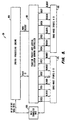
- Phantom packet and Logical Collision domain controller 110 includes, for an eight port switch, eight port x receive packet destination decoders 200x (one per port) and eight blocking 7-input OR gates (G0-G7).
- Each decoder 200x receives CRSx from a MAC 115 and, in response to a decoded PORT ID signal identifying port y, asserts a decoder output signal DECODEy when CRSx is asserted.
- Corresponding DECODEy signals from decoder 200x i.e., those that identify port y
- Each decoder 200x includes a 3-to-8 decoder 250, seven dual-input NOR gates (G10-G16) and an inverter G17.
- CRSx is input to inverter G17.
- An output of inverter G17 is coupled to a first input of each gate G10-G16.
- An output of NOR gates GX provides the DECODEy signal.
- the CRSx input is also provided to an enable input of decoder 250.
- Decoder 250 responsive to the PORT ID signal and assertion of the enable signal, converts a bit code identifying the active receiving port to an eight bit code.
- One of each of the bits of the converted PORT ID code is coupled to one of the second inputs of the NOR gates G10-G16.
- port 0 is an active receiver and the identified destination output port is port 7 (assume CRS7 is asserted)
- CRS7 is routed at DECODE0 to blocking OR gate G0.
- DECODE0 is active (e.g., active CRS7 routed to G0)
- BLOCKO is asserted
- a phantom packet is transmitted into the collision domain coupled to port 0 for as long as CRS7 remains asserted.
- the delay in deasserting the CRSx signal can be minimized by ensuring that the MAC controlling the CRS signal deasserts it as quickly as possible.
- the delay can be mitigated completely if the CRSx signal is returned from a switch port that is transmitting. Since the transmitting MAC is aware of the end of the packet in advance (since it is stored in it's internal FIFO), a transmitting MAC can effectively advance the deassertion of it's CRS output (by a predictable time period) in relation to the actual packet completion.
- the logic delays can be eliminated, and in fact the station which is being blocked by the phantom packet, can be prioritized slightly. Dropping the CRSx indication early, deasserts the BLOCKx signal, and ceases the transmission of the phantom packet. Allowing this to occur at a previously blocked input port, slightly earlier than the carrier indication of the ports currently engaged in a packet transfer, allows the IPG timer of the previously blocked station to begin timing out, and allows the station to aggressively contend for the logical collision domain.
- Switch processing engine 100 is assumed to be able to read the appropriate Throttle Count values when two input ports are active and simultaneously (or closely separated in time) request access to the same output resource. Switch processing engine 100 would then choose the port with the highest Throttle Count to be allowed to occupy the output port, while the port with the lower Throttle Count value would have its port ID written to the Logical Collision domain controller for the associated output port.
- the present invention provides a simple, efficient solution to a problem of flow control in a half-duplex Ethernet switch. While the above is a complete description of the preferred embodiments of the invention, various alternatives, modifications, and equivalents may be used.
- Modifications include creating the phantom packet with a specific preamble or SFD pattern, which identifies the packet as being a phantom.
- the phantom packet could be formed to contain data field(s) and a valid CRC so that information could be passed within the phantom packet, which may be useful to some devices (full duplex capable devices for instance).
- enhanced end stations could be deployed to react differently to the phantom packet. For instance, read and use the data passed within the phantom packet, or cease transmission for a specified period on receipt of the phantom packet.
- Resumption of transmission by the end station could be accomplished by either transmitting a "resume” message, or merely allowing the end station to resume transmission after a fixed or variable delay.
- the phantom packet is used die to its simplicity and interoperablity with existing Ethernet communications systems, other derivatives of Ethernet or other communications systems may use an alternative signaling method to effectively indicate that the packet cannot currently be accepted, and that it should be re-tried after a suitable delay. Therefore, the above description should not be taken as limiting the scope of the invention which is defined by the appended claims.
Landscapes
- Engineering & Computer Science (AREA)
- Computer Networks & Wireless Communication (AREA)
- Signal Processing (AREA)
- Small-Scale Networks (AREA)
- Data Exchanges In Wide-Area Networks (AREA)
Applications Claiming Priority (3)
| Application Number | Priority Date | Filing Date | Title |
|---|---|---|---|
| US480497 | 1983-03-30 | ||
| US08/480,497 US5859837A (en) | 1995-06-07 | 1995-06-07 | Flow control method and apparatus for ethernet packet switched hub |
| PCT/US1996/004658 WO1996041456A1 (en) | 1995-06-07 | 1996-04-04 | Flow control method and apparatus for ethernet packet switched hub |
Publications (2)
| Publication Number | Publication Date |
|---|---|
| EP0830769A1 EP0830769A1 (en) | 1998-03-25 |
| EP0830769B1 true EP0830769B1 (en) | 2000-06-07 |
Family
ID=23908190
Family Applications (1)
| Application Number | Title | Priority Date | Filing Date |
|---|---|---|---|
| EP96911582A Expired - Lifetime EP0830769B1 (en) | 1995-06-07 | 1996-04-04 | Flow control method and apparatus for ethernet packet switched hub |
Country Status (7)
| Country | Link |
|---|---|
| US (1) | US5859837A (ko) |
| EP (1) | EP0830769B1 (ko) |
| JP (1) | JP3684404B2 (ko) |
| KR (1) | KR19990021933A (ko) |
| DE (1) | DE69608800T2 (ko) |
| TW (1) | TW312068B (ko) |
| WO (1) | WO1996041456A1 (ko) |
Cited By (1)
| Publication number | Priority date | Publication date | Assignee | Title |
|---|---|---|---|---|
| DE102004050423A1 (de) * | 2004-10-15 | 2006-04-20 | Bosch Rexroth Ag | Kommunikationssystem und Verfahren zur Synchronisation desselben |
Families Citing this family (55)
| Publication number | Priority date | Publication date | Assignee | Title |
|---|---|---|---|---|
| US6035105A (en) * | 1996-01-02 | 2000-03-07 | Cisco Technology, Inc. | Multiple VLAN architecture system |
| US6151326A (en) * | 1996-10-24 | 2000-11-21 | Hewlett-Packard Company | Method and apparatus for automatic device segmentation and port-to-segment distribution |
| US6282195B1 (en) * | 1997-01-09 | 2001-08-28 | Silicon Graphics, Inc. | Packetized data transmissions in a switched router architecture |
| US6185630B1 (en) | 1997-02-14 | 2001-02-06 | Advanced Micro Devices, Inc. | Device initializing system with programmable array logic configured to cause non-volatile memory to output address and data information to the device in a prescribed sequence |
| US5931915A (en) * | 1997-05-13 | 1999-08-03 | International Business Machines Corporation | Method for processing early arrival messages within a multinode asynchronous data communications system |
| US5935268A (en) * | 1997-06-03 | 1999-08-10 | Bay Networks, Inc. | Method and apparatus for generating an error detection code for a modified data packet derived from an original data packet |
| JP3116860B2 (ja) | 1997-06-05 | 2000-12-11 | 日本電気株式会社 | データ処理装置、データ処理システム、データ処理方法、情報記憶媒体 |
| US6363067B1 (en) | 1997-09-17 | 2002-03-26 | Sony Corporation | Staged partitioned communication bus for a multi-port bridge for a local area network |
| US6301256B1 (en) | 1997-09-17 | 2001-10-09 | Sony Corporation | Selection technique for preventing a source port from becoming a destination port in a multi-port bridge for a local area network |
| US6252879B1 (en) | 1997-09-17 | 2001-06-26 | Sony Corporation | Single counter for controlling multiple finite state machines in a multi-port bridge for local area network |
| US6751225B1 (en) | 1997-09-17 | 2004-06-15 | Sony Corporation | Port within a multi-port bridge including a buffer for storing routing information for data packets received in the port |
| US6617879B1 (en) | 1997-09-17 | 2003-09-09 | Sony Corporation | Transparently partitioned communication bus for multi-port bridge for a local area network |
| US6442168B1 (en) | 1997-09-17 | 2002-08-27 | Sony Corporation | High speed bus structure in a multi-port bridge for a local area network |
| US6446173B1 (en) | 1997-09-17 | 2002-09-03 | Sony Corporation | Memory controller in a multi-port bridge for a local area network |
| US6308218B1 (en) | 1997-09-17 | 2001-10-23 | Sony Corporation | Address look-up mechanism in a multi-port bridge for a local area network |
| US7570583B2 (en) * | 1997-12-05 | 2009-08-04 | Cisco Technology, Inc. | Extending SONET/SDH automatic protection switching |
| US6687754B1 (en) * | 1998-08-27 | 2004-02-03 | Intel Corporation | Method of detecting a device in a network |
| US6370115B1 (en) * | 1998-09-09 | 2002-04-09 | Stmicroelectronics, Inc. | Ethernet device and method for applying back pressure |
| US6667985B1 (en) * | 1998-10-28 | 2003-12-23 | 3Com Technologies | Communication switch including input bandwidth throttling to reduce output congestion |
| US6885657B1 (en) | 1998-11-30 | 2005-04-26 | Broadcom Corporation | Network telephony system |
| KR100308902B1 (ko) * | 1998-12-28 | 2001-11-15 | 윤종용 | 이더넷 매체접속제어계층에서 수신패킷의 에러 처리 방법 및 장치 |
| US6785742B1 (en) * | 1999-02-24 | 2004-08-31 | Brocade Communications Systems, Inc. | SCSI enclosure services |
| GB2348580B (en) | 1999-03-30 | 2001-03-14 | 3Com Corp | System and method for congestion control in packet-based communication networks |
| US7046632B2 (en) * | 2000-04-01 | 2006-05-16 | Via Technologies, Inc. | Method and switch controller for relieving flow congestion in network |
| US20050030898A1 (en) * | 2000-05-08 | 2005-02-10 | Metrobility Optical Systems Inc. | Using inter-packet gap as management channel |
| US6856595B1 (en) | 2000-05-19 | 2005-02-15 | Mosaid Technologies, Inc. | Method and apparatus for providing input back pressure in an output buffered switch |
| NO313778B1 (no) * | 2000-06-06 | 2002-11-25 | Ontime Networks As | Fremgangsmåte for å sikre aksess til et transmisjonsmedium ved et forhåndsbestemt tidspunkt og en tidsserver som benytterfremgangsmåten |
| US6981054B1 (en) | 2000-06-06 | 2005-12-27 | Advanced Micro Devices, Inc. | Flow control arrangement in a network switch based on priority traffic |
| JP3407717B2 (ja) * | 2000-06-20 | 2003-05-19 | 日本電気株式会社 | Lan通信路制御システム及び制御方法 |
| DE10039838A1 (de) * | 2000-08-10 | 2002-02-21 | Philips Corp Intellectual Pty | Aktivitätsdetektion in einem Sternknoten mit mehreren gekoppelten Netzknoten |
| GB2370184B (en) * | 2000-12-13 | 2003-06-18 | 3Com Corp | Selectable bandwidth facility for a network port |
| US7058070B2 (en) * | 2001-05-01 | 2006-06-06 | Integrated Device Technology, Inc. | Back pressure control system for network switch port |
| US20030101268A1 (en) * | 2001-05-18 | 2003-05-29 | Davidson David Scott | High-level extensible markup language (XML) structure and communication process |
| US7082104B2 (en) * | 2001-05-18 | 2006-07-25 | Intel Corporation | Network device switch |
| US7142552B2 (en) * | 2002-04-08 | 2006-11-28 | International Business Machines Corporation | Method and system for priority enforcement with flow control |
| US7304940B2 (en) * | 2002-09-05 | 2007-12-04 | World Wide Packets, Inc. | Network switch assembly, network switching device, and method |
| US7633861B2 (en) * | 2003-04-25 | 2009-12-15 | Alcatel-Lucent Usa Inc. | Fabric access integrated circuit configured to bound cell reorder depth |
| US7646724B2 (en) | 2003-05-12 | 2010-01-12 | International Business Machines Corporation | Dynamic blocking in a shared host-network interface |
| US20050138238A1 (en) * | 2003-12-22 | 2005-06-23 | James Tierney | Flow control interface |
| US7355975B2 (en) * | 2004-04-30 | 2008-04-08 | International Business Machines Corporation | Method and apparatus for group communication with end-to-end reliability |
| US7680053B1 (en) * | 2004-10-29 | 2010-03-16 | Marvell International Ltd. | Inter-device flow control |
| US8004970B2 (en) * | 2005-08-30 | 2011-08-23 | International Business Machines Corporation | Method, system and program product for setting a transmission rate in a network |
| US7729274B2 (en) * | 2006-03-31 | 2010-06-01 | Ciena Corporation | Smart ethernet mesh edge device |
| US8218445B2 (en) * | 2006-06-02 | 2012-07-10 | Ciena Corporation | Smart ethernet edge networking system |
| US8363545B2 (en) * | 2007-02-15 | 2013-01-29 | Ciena Corporation | Efficient ethernet LAN with service level agreements |
| US9621375B2 (en) | 2006-09-12 | 2017-04-11 | Ciena Corporation | Smart Ethernet edge networking system |
| US8509062B2 (en) * | 2006-08-07 | 2013-08-13 | Ciena Corporation | Smart ethernet edge networking system |
| JP2008172515A (ja) * | 2007-01-11 | 2008-07-24 | Sony Corp | 送信装置および方法、通信装置、並びにプログラム |
| US20090188561A1 (en) * | 2008-01-25 | 2009-07-30 | Emcore Corporation | High concentration terrestrial solar array with III-V compound semiconductor cell |
| US8819161B1 (en) | 2010-01-18 | 2014-08-26 | Marvell International Ltd. | Auto-syntonization and time-of-day synchronization for master-slave physical layer devices |
| US8539068B2 (en) * | 2010-06-07 | 2013-09-17 | Salesforce.Com, Inc. | Methods and systems for providing customized domain messages |
| GB2482013B (en) * | 2010-07-15 | 2016-08-03 | Cray Uk Ltd | Crossbar packet switch with simultaneous reassertion of blocked requests |
| KR102171117B1 (ko) * | 2013-08-30 | 2020-10-29 | 삼성전자주식회사 | 패킷 송수신 방법 및 그에 따른 단말, 그에 따른 시스템 |
| WO2019173618A1 (en) * | 2018-03-08 | 2019-09-12 | Fungible, Inc. | Reliable communications using a point to point protocol |
| US10671554B1 (en) | 2019-02-08 | 2020-06-02 | Advanced Micro Devices, Inc. | Credit based flow control mechanism for use in multiple link width interconnect systems |
Family Cites Families (11)
| Publication number | Priority date | Publication date | Assignee | Title |
|---|---|---|---|---|
| US4500990A (en) * | 1982-04-14 | 1985-02-19 | Nec Corporation | Data communication device including circuitry responsive to an overflow of an input packet buffer for causing a collision |
| US5140585A (en) * | 1990-07-19 | 1992-08-18 | Kabushiki Kaisha Toshiba | Star local-area network system |
| US5285449A (en) * | 1991-04-03 | 1994-02-08 | International Business Machines Corporation | Protocol for hybrid local area networks |
| US5339313A (en) * | 1991-06-28 | 1994-08-16 | Digital Equipment Corporation | Method and apparatus for traffic congestion control in a communication network bridge device |
| US5177788A (en) * | 1991-10-15 | 1993-01-05 | Ungermann-Bass, Inc. | Network message security method and apparatus |
| US5305321A (en) * | 1992-02-24 | 1994-04-19 | Advanced Micro Devices | Ethernet media access controller with external address detection interface and associated method |
| US5351241A (en) * | 1992-12-24 | 1994-09-27 | Intel Corporation | Twisted pair ethernet hub for a star local area network |
| FR2701618B1 (fr) * | 1993-02-16 | 1995-06-23 | Tremel Jean Yves | Procede de mesure de parametres de performance d'un reseau atm et dispositif de mise en oeuvre. |
| EP0648034A1 (en) * | 1993-09-08 | 1995-04-12 | ALCATEL BELL Naamloze Vennootschap | Communication network and computer network server and interface modules used therein |
| US5469439A (en) * | 1994-05-04 | 1995-11-21 | Hewlett Packard Company | Two priority fair distributed round robin protocol for a network having cascaded hubs |
| US5546385A (en) * | 1995-01-19 | 1996-08-13 | Intel Corporation | Flexible switching hub for a communication network |
-
1995
- 1995-06-07 US US08/480,497 patent/US5859837A/en not_active Expired - Lifetime
-
1996
- 1996-03-02 TW TW085102565A patent/TW312068B/zh active
- 1996-04-04 DE DE69608800T patent/DE69608800T2/de not_active Expired - Lifetime
- 1996-04-04 KR KR1019970708408A patent/KR19990021933A/ko not_active Application Discontinuation
- 1996-04-04 WO PCT/US1996/004658 patent/WO1996041456A1/en not_active Application Discontinuation
- 1996-04-04 EP EP96911582A patent/EP0830769B1/en not_active Expired - Lifetime
- 1996-04-04 JP JP50046197A patent/JP3684404B2/ja not_active Expired - Fee Related
Cited By (2)
| Publication number | Priority date | Publication date | Assignee | Title |
|---|---|---|---|---|
| DE102004050423A1 (de) * | 2004-10-15 | 2006-04-20 | Bosch Rexroth Ag | Kommunikationssystem und Verfahren zur Synchronisation desselben |
| US8170066B2 (en) | 2004-10-15 | 2012-05-01 | Bosch Rexroth Ag | Communication system and method for synchronization of the same |
Also Published As
| Publication number | Publication date |
|---|---|
| JPH11506287A (ja) | 1999-06-02 |
| DE69608800T2 (de) | 2001-01-18 |
| WO1996041456A1 (en) | 1996-12-19 |
| JP3684404B2 (ja) | 2005-08-17 |
| KR19990021933A (ko) | 1999-03-25 |
| TW312068B (ko) | 1997-08-01 |
| US5859837A (en) | 1999-01-12 |
| EP0830769A1 (en) | 1998-03-25 |
| DE69608800D1 (de) | 2000-07-13 |
Similar Documents
| Publication | Publication Date | Title |
|---|---|---|
| EP0830769B1 (en) | Flow control method and apparatus for ethernet packet switched hub | |
| EP0830768B1 (en) | Enhancements to 802.3 media access control and associate signaling schemes for full duplex ethernet | |
| US6198722B1 (en) | Flow control method for networks | |
| US6192422B1 (en) | Repeater with flow control device transmitting congestion indication data from output port buffer to associated network node upon port input buffer crossing threshold level | |
| US6442170B1 (en) | Adaptive addressing filtering | |
| US5920698A (en) | Automatic detection of a similar device at the other end of a wire in a computer network | |
| US6002675A (en) | Method and apparatus for controlling transmission of data over a network | |
| US5568476A (en) | Method and apparatus for avoiding packet loss on a CSMA/CD-type local area network using receive-sense-based jam signal | |
| EP1106018B1 (en) | Telecommunication network with variable address learning, switching and routing | |
| WO1999009713A1 (en) | Circuits and methods for a ring network | |
| JPH05219088A (ja) | 通信網制御方法 | |
| Alves et al. | Ethernet goes real-time: a survey on research and technological developments | |
| EP0853405A2 (en) | Ethernet network with credit based flow control | |
| US6370115B1 (en) | Ethernet device and method for applying back pressure | |
| EP0800733B1 (en) | Programmable delay of disrupt for secure networks | |
| EP0853406A2 (en) | Management of a computer network switched repeater | |
| AU714667C (en) | Buffered repeater with early filling of transmit buffer | |
| Ma et al. | Prioritized protocols for multi-bus local area networks |
Legal Events
| Date | Code | Title | Description |
|---|---|---|---|
| PUAI | Public reference made under article 153(3) epc to a published international application that has entered the european phase |
Free format text: ORIGINAL CODE: 0009012 |
|
| 17P | Request for examination filed |
Effective date: 19971107 |
|
| AK | Designated contracting states |
Kind code of ref document: A1 Designated state(s): DE FR GB |
|
| GRAG | Despatch of communication of intention to grant |
Free format text: ORIGINAL CODE: EPIDOS AGRA |
|
| 17Q | First examination report despatched |
Effective date: 19990819 |
|
| GRAG | Despatch of communication of intention to grant |
Free format text: ORIGINAL CODE: EPIDOS AGRA |
|
| GRAH | Despatch of communication of intention to grant a patent |
Free format text: ORIGINAL CODE: EPIDOS IGRA |
|
| GRAH | Despatch of communication of intention to grant a patent |
Free format text: ORIGINAL CODE: EPIDOS IGRA |
|
| GRAA | (expected) grant |
Free format text: ORIGINAL CODE: 0009210 |
|
| AK | Designated contracting states |
Kind code of ref document: B1 Designated state(s): DE FR GB |
|
| REF | Corresponds to: |
Ref document number: 69608800 Country of ref document: DE Date of ref document: 20000713 |
|
| ET | Fr: translation filed | ||
| PLBE | No opposition filed within time limit |
Free format text: ORIGINAL CODE: 0009261 |
|
| STAA | Information on the status of an ep patent application or granted ep patent |
Free format text: STATUS: NO OPPOSITION FILED WITHIN TIME LIMIT |
|
| 26N | No opposition filed | ||
| REG | Reference to a national code |
Ref country code: GB Ref legal event code: IF02 |
|
| REG | Reference to a national code |
Ref country code: GB Ref legal event code: 732E Free format text: REGISTERED BETWEEN 20091210 AND 20091216 |
|
| PGFP | Annual fee paid to national office [announced via postgrant information from national office to epo] |
Ref country code: GB Payment date: 20100312 Year of fee payment: 15 |
|
| PGFP | Annual fee paid to national office [announced via postgrant information from national office to epo] |
Ref country code: FR Payment date: 20100420 Year of fee payment: 15 |
|
| PGFP | Annual fee paid to national office [announced via postgrant information from national office to epo] |
Ref country code: DE Payment date: 20100430 Year of fee payment: 15 |
|
| REG | Reference to a national code |
Ref country code: FR Ref legal event code: TP |
|
| REG | Reference to a national code |
Ref country code: DE Ref legal event code: R119 Ref document number: 69608800 Country of ref document: DE |
|
| REG | Reference to a national code |
Ref country code: DE Ref legal event code: R119 Ref document number: 69608800 Country of ref document: DE |
|
| GBPC | Gb: european patent ceased through non-payment of renewal fee |
Effective date: 20110404 |
|
| REG | Reference to a national code |
Ref country code: FR Ref legal event code: ST Effective date: 20111230 |
|
| PG25 | Lapsed in a contracting state [announced via postgrant information from national office to epo] |
Ref country code: FR Free format text: LAPSE BECAUSE OF NON-PAYMENT OF DUE FEES Effective date: 20110502 |
|
| PG25 | Lapsed in a contracting state [announced via postgrant information from national office to epo] |
Ref country code: GB Free format text: LAPSE BECAUSE OF NON-PAYMENT OF DUE FEES Effective date: 20110404 |
|
| PG25 | Lapsed in a contracting state [announced via postgrant information from national office to epo] |
Ref country code: DE Free format text: LAPSE BECAUSE OF NON-PAYMENT OF DUE FEES Effective date: 20111031 |