EP0830647B1 - Automatisches fehlertolerantes steuerungssystem unter verwendung analytischer redundanz - Google Patents
Automatisches fehlertolerantes steuerungssystem unter verwendung analytischer redundanz Download PDFInfo
- Publication number
- EP0830647B1 EP0830647B1 EP96921509A EP96921509A EP0830647B1 EP 0830647 B1 EP0830647 B1 EP 0830647B1 EP 96921509 A EP96921509 A EP 96921509A EP 96921509 A EP96921509 A EP 96921509A EP 0830647 B1 EP0830647 B1 EP 0830647B1
- Authority
- EP
- European Patent Office
- Prior art keywords
- signal
- sensor
- flight control
- status signal
- transformed
- Prior art date
- Legal status (The legal status is an assumption and is not a legal conclusion. Google has not performed a legal analysis and makes no representation as to the accuracy of the status listed.)
- Expired - Lifetime
Links
- RZVHIXYEVGDQDX-UHFFFAOYSA-N 9,10-anthraquinone Chemical compound C1=CC=C2C(=O)C3=CC=CC=C3C(=O)C2=C1 RZVHIXYEVGDQDX-UHFFFAOYSA-N 0.000 claims abstract description 85
- 230000001131 transforming effect Effects 0.000 claims abstract description 19
- 238000000034 method Methods 0.000 claims abstract description 12
- 238000012545 processing Methods 0.000 claims description 15
- 230000004044 response Effects 0.000 claims description 14
- 230000009466 transformation Effects 0.000 claims description 10
- 230000000116 mitigating effect Effects 0.000 abstract 1
- 238000001514 detection method Methods 0.000 description 25
- 230000001419 dependent effect Effects 0.000 description 14
- 238000005259 measurement Methods 0.000 description 8
- 239000013598 vector Substances 0.000 description 7
- 230000008859 change Effects 0.000 description 6
- 238000013461 design Methods 0.000 description 6
- 230000000694 effects Effects 0.000 description 6
- 238000013178 mathematical model Methods 0.000 description 6
- 238000010586 diagram Methods 0.000 description 4
- 230000015572 biosynthetic process Effects 0.000 description 3
- 238000002955 isolation Methods 0.000 description 3
- 239000011159 matrix material Substances 0.000 description 3
- 238000003786 synthesis reaction Methods 0.000 description 3
- 238000013459 approach Methods 0.000 description 2
- 230000008901 benefit Effects 0.000 description 2
- 239000000523 sample Substances 0.000 description 2
- 238000012546 transfer Methods 0.000 description 2
- 238000000844 transformation Methods 0.000 description 2
- 238000010200 validation analysis Methods 0.000 description 2
- PXFBZOLANLWPMH-UHFFFAOYSA-N 16-Epiaffinine Natural products C1C(C2=CC=CC=C2N2)=C2C(=O)CC2C(=CC)CN(C)C1C2CO PXFBZOLANLWPMH-UHFFFAOYSA-N 0.000 description 1
- 238000002485 combustion reaction Methods 0.000 description 1
- 230000006837 decompression Effects 0.000 description 1
- 230000003247 decreasing effect Effects 0.000 description 1
- 238000011156 evaluation Methods 0.000 description 1
- 239000000446 fuel Substances 0.000 description 1
- 230000003993 interaction Effects 0.000 description 1
- 239000000203 mixture Substances 0.000 description 1
- 238000012544 monitoring process Methods 0.000 description 1
- 230000008569 process Effects 0.000 description 1
- 230000009897 systematic effect Effects 0.000 description 1
- 230000001052 transient effect Effects 0.000 description 1
Images



Classifications
-
- G—PHYSICS
- G05—CONTROLLING; REGULATING
- G05B—CONTROL OR REGULATING SYSTEMS IN GENERAL; FUNCTIONAL ELEMENTS OF SUCH SYSTEMS; MONITORING OR TESTING ARRANGEMENTS FOR SUCH SYSTEMS OR ELEMENTS
- G05B9/00—Safety arrangements
- G05B9/02—Safety arrangements electric
-
- G—PHYSICS
- G05—CONTROLLING; REGULATING
- G05B—CONTROL OR REGULATING SYSTEMS IN GENERAL; FUNCTIONAL ELEMENTS OF SUCH SYSTEMS; MONITORING OR TESTING ARRANGEMENTS FOR SUCH SYSTEMS OR ELEMENTS
- G05B23/00—Testing or monitoring of control systems or parts thereof
- G05B23/02—Electric testing or monitoring
- G05B23/0205—Electric testing or monitoring by means of a monitoring system capable of detecting and responding to faults
- G05B23/0259—Electric testing or monitoring by means of a monitoring system capable of detecting and responding to faults characterized by the response to fault detection
- G05B23/0286—Modifications to the monitored process, e.g. stopping operation or adapting control
-
- G—PHYSICS
- G05—CONTROLLING; REGULATING
- G05B—CONTROL OR REGULATING SYSTEMS IN GENERAL; FUNCTIONAL ELEMENTS OF SUCH SYSTEMS; MONITORING OR TESTING ARRANGEMENTS FOR SUCH SYSTEMS OR ELEMENTS
- G05B9/00—Safety arrangements
- G05B9/02—Safety arrangements electric
- G05B9/03—Safety arrangements electric with multiple-channel loop, i.e. redundant control systems
-
- G—PHYSICS
- G05—CONTROLLING; REGULATING
- G05D—SYSTEMS FOR CONTROLLING OR REGULATING NON-ELECTRIC VARIABLES
- G05D1/00—Control of position, course, altitude or attitude of land, water, air or space vehicles, e.g. using automatic pilots
- G05D1/0055—Control of position, course, altitude or attitude of land, water, air or space vehicles, e.g. using automatic pilots with safety arrangements
- G05D1/0077—Control of position, course, altitude or attitude of land, water, air or space vehicles, e.g. using automatic pilots with safety arrangements using redundant signals or controls
Definitions
- the present invention relates to a fault tolerant automatic control system for a dynamic device (e.g. an airplane), wherein the fault tolerant control system utilizes analytic redundancy. More particularly, the present invention relates to a fault tolerant control system including (i) a coordinate transforming diffeomorphism and (ii) a feedback control law (algorithm), which produce a control system model that is linear time invariant (the feedback control law which renders the control system model linear time invariant is hereinafter termed "a feedback LTI'ing control law") so that sensor/actuator failures are easily identified and the automatic control algorithm may be reconfigured based on the detected failures.
- a feedback LTI'ing control law the feedback control law which renders the control system model linear time invariant
- the invention pertains to the automatic control of parameter-dependent dynamic systems (such as an aircraft in flight) in the face of a failure of any one of the actuators or sensors of the control system.
- the fault tolerant automatic control system is capable of performing the functions of automatic failure detection and control system reconfiguration for a system whose dynamic behavior depends on the parameters of the system, such as an airplane dependent on air speed, altitude, etc.
- multi-link robotic manipulators exhibit dynamic behavior dependent on link configuration.
- the dynamic response with the links fully extended will be, for example, different from the . case where all links are retracted.
- the parameters upon which the dynamics depend are link configuration.
- the need for compactness and the environment in which manipulators are used do not permit the necessary real estate for including multiply-redundant hardware.
- an important issue is the parameter-dependent nature of most control systems.
- an aircraft flying at steady speed and altitude is an example of a linear time invariant system since the dynamic behavior of the aircraft in response to small disturbances about this operating condition may be well described by a mathematical model which is linear and has constant parameters.
- Aircraft typically operate over a large range in parameters such as altitude, speed, mass, center of mass location, etc.
- a mathematical model of the aircraft dynamics must necessarily include the effects of these and other parameters in order to accurately describe the dynamic behavior of the aircraft due to external disturbances and control inputs for any combinations of these parameter values.
- an adequate mathematical model in such a case is linear, but parameter dependent, with the parameters varying over wide ranges.
- a multi-link robotic manipulator is another example in the class of linear parameter-dependent systems.
- Existing fault tolerant control systems which have good design and synthesis attributes are limited in application to linear time invariant systems, and are not directly applicable to the more common linear parameter-dependent systems.
- DE 39 29 404 A1 discloses a fault tolerant automatic control system utilizing analytic redundancy.
- the system can be used for the recognition and identification of faults of failures in sensors detecting variables of states.
- This known technology involves determining a set of validation sectors which span the space of the measurement matrix, then determining a set of parity vectors from measured signals such that the parity vectors can be written as a linear combination of the validation sectors. Finally some further magnitude evaluation is performed to determine failures.
- This object is achieved by the features of the independent claims.
- the dependent claims develop further the central idea of the present invention.
- the present invention provides analytic redundancy by comparing measured system behavior with expected system behavior and detecting failures based on this comparison. After failure detection, the control system algorithm is reconfigured to ignore or compensate for the failed component.
- a fault tolerant control system for a dynamic device having a sensor and a predetermined control algorithm includes means for receiving a status signal from the sensor. Processing means are provided for (i) transforming the sensor status signal and a predetermined reference signal into a linear time invariant coordinate system, (ii) generating a sensor estimate in the linear time invariant coordinate system based on the transformed sensor status signal and the transformed reference signal, (iii) transforming the sensor estimate into a physical coordinate system, (iv) detecting an error in the sensor status signal based on the transformed sensor estimate and the sensor status signal, and (v) reconfiguring the predetermined control algorithm based on the detected error.
- a fault tolerant aircraft flight control system for detecting a failure in at least one of a flight control sensor and a flight control actuator, and for reconfiguring the flight control system to minimize the detected failure includes input means for receiving a status signal indicating status of at least one of a flight control sensor and a flight control actuator.
- a processor for (i) comparing the received status signal to a predetermined flight control reference signal and providing a flight control adjustment signal based on the comparison, (ii) transforming the status signal, the reference signal, and the adjustment signal into a linear time invariant coordinate system, (iii) determining an expected response of the at least one of a flight control sensor and a flight control actuator based on the transformed signals in the linear time invariant coordinate system, and generating an expected response signal corresponding thereto; (iv) transforming the expected response signal from the linear time invariant coordinate system to a physical coordinate system, (v) comparing the transformed expected response signal to the received status signal and generating an error signal corresponding thereto, (vi) determining that a failure has occurred in the at least one of flight control sensor and a flight control actuator based on the error signal, and (vii) generating a reconfigure signal to reconfigure the flight control system to minimize the effect of the detected failure.
- algorithm includes the steps of (i) inputting a status signal from the sensor, (ii) transforming the sensor status signal and a predetermined reference signal into a linear time invariant coordinate system, (iii) generating a sensor estimate in the linear time invariant coordinate system based on the transformed sensor status signal and transformed reference signal, (iv) transforming the sensor estimate into a physical coordinate system, (v) detecting an error in the sensor status signal based on the transformed sensor estimate and the sensor status signal, and (vi) reconfiguring the predetermined control algorithm based on the detected error.
- the present invention will be described with respect to an embodiment incorporated in an aircraft automatic flight control system for maintaining desired handling qualities and dynamic performance of the aircraft even in the event of sensor or actuator failure.
- the present invention is also applicable to other dynamic devices such as vehicles including automobiles, trains, robots; and to other dynamic devices requiring monitoring and control including internal combustion engines, wind and solar generators, etc.
- Fig. 1 is a perspective view of a UAV aircraft 1 having flight control surfaces such as ailerons 101, elevator 102, and rudder 103. Each flight control surface has an actuator (not shown in Fig. 1) for controlling the corresponding surface to achieves controlled flight. Of course, other flight control actuators may be provided such as throttle, propeller, fuel mixture, elevator trim, brake, cowl flap, etc.
- the actuators described above are controlled by a flight control computer 104 which outputs actuator control signals in accordance with a flight control algorithm (hereinafter termed flight control laws), in order to achieve controlled flight.
- the flight control computer 104 receives as inputs sensor status signals from the sensors disposed in sensor rack 105.
- Various aircraft performance sensors disposed about the aircraft monitor and provide signals to the sensor rack 105, which, in turn, provides the sensor signals to the flight control computer 104.
- provided aircraft sensors may include: an altimeter; an airspeed probe; a vertical gyro for measuring roll and pitch attitudes; rate gyros for measuring roll, pitch, and yaw angular rates; a magnetometer for directional information; alpha-beta air probes for measuring angle of attack and sideslip angle; etc.
- the flight control computer 104 uses sensor status inputs and a flight control algorithm, the flight control computer 104 outputs actuator commands to control the various flight control surfaces to maintain stable flight.
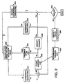
- Fig. 2 is a functional block diagram for explaining the functional aspects according to the present invention.
- Fig. 2 represents an algorithm which provides sensor or actuator failure detection and isolation for an aircraft dynamic system whose dynamics vary with parameter value (vary over time), while taking account of the parameter dependence in both parameter value as well as the rate of change of parameter values of the dynamic system to be controlled.
- a mathematical model of the parameter-dependent dynamic system depicted in Fig. 1 is written in a physical coordinate system (hereinafter called a coordinate system in X-space) which can be represented on the physical dynamic system.
- a Cartesian axis system may have one axis disposed along the fuselage toward the nose, one axis disposed along the wing toward the right wingtip, and one axis disposed straight down from the center of mass, perpendicular to the plane incorporating the first two axes. Measurements via sensors placed along or about these axes provide information regarding for example, aircraft pitch, roll attitude, side slip, angle of attack, etc.
- a reference signal Yr is an actuation input commanded by the ground-based UAV pilot.
- the actuation input of the stick moved forward is the reference signal Yr input to the flight control computer.
- the flight control computer subtracts from Yr the measured actuator or sensor signal Ym (e.g., the actual stick location), and determines a difference signal Ydiff.
- This difference signal is input to an appropriate one or ones of the flight control laws 208 (of the flight control algorithm) to determine an actual actuator command Ya which affects aircraft dynamics 209 by, for example, causing the elevator to move downward thereby decreasing pitch and thus increasing airspeed.
- Flight control laws are typically a plurality of equations used to control flight in a predictable way.
- the pitch attitude initially is determined to be even, thus producing a very small G2(pitch attitude) term.
- the elevator actuator command is thus the sum of G1 and G2, i.e., a large downward elevator actuator command.
- Flight control laws are well known to those of ordinary skill in flight and vehicle controls and will not be described in greater detail herein. Reference may be had to the text "AIRCRAFT DYNAMICS AND AUTOMATIC CONTROL", by McRuer, et al., Princeton University Press, 1973, incorporated herein by reference.
- the output of flight control law 208 is an actuator command Ya which produces an effect on aircraft dynamics 209 which represents the dynamic behavior of the aircraft.
- the measured output Ym of aircraft dynamics 209 represents the physical dynamic response of the aircraft to the actuator input Ya.
- the interaction of the flight control law 208 and aircraft dynamics 209 is well known to those of ordinary skill in the art.
- the present invention achieves fault detection and isolation and control law reconfiguration by transforming the various actuator signals into a linear time invariant coordinate system within which can be performed failure detection and isolation for dynamic systems whose parameters vary over time. That is, a failure detection filter may be implemented in so-called Z-space in which the system may be represented as linear time invariant and is independent of the dynamic system parameters.
- the failure detection filter is relatively simple in design and implementation, and is applicable to parameter-dependent dynamic systems whose parameters may vary in value over the full parameter envelope at arbitrary rates.
- non-stationary aircraft flight dynamics equations are transformed into stationary linear equations in a general and systematic fashion.
- a set of constant coefficient differential equations is generated in Z-space for modeling the effects of failures in aircraft systems.
- linear time invariant failure detection algorithms may be directly applied to generate in Z-space a system model of expected aircraft dynamic behavior. This model is then compared to the sensor-measured system behavior to detect aircraft control failures and to reconfigure the aircraft controls to minimize the failure.
- a coordinate transformation or diffeomorphism 201 is determined which transforms the physical coordinates (X-space) of the aircraft dynamic mathematical model to a new set of coordinates (Z-space).
- a feedback LTI'ing control law 202 which includes terms that account for both the current parameter values as well as the rate of change of the parameter values, it is then possible to mathematically treat the dynamic system as a linear time invariant system in Z-space.
- This methodology of feedback LTI-zation (by which the combination of diffeomorphism and feedback LTI-ing control yields the system mathematically linear time invariant) is an extension of a concept of input state feedback linearization [e.g., see Hunt, et al., "Global Transformations Of Non-Linear Systems", IEEE Transactions On Automatic Control, volume AC-28, no. 1, January, 1983; G. Meyer, et al., "Application Of Non-Linear Transformations To Automatic Flight Control," Automatica, volume 20, no. 1, pp. 103-7, Pergamon Pres. Ltd., 1984;] to account for parameter rate of change terms, and is outlined in the PhD. thesis of the inventor, Dr.
- the diffeomorphism is the system coordinates transformation, and is key to defining the transformed coordinates space in which the failure detection filter 203 is defined. Specifically, the coordinates transformation maps the physical coordinates (X-space) model into a set of coordinates in 2-space.
- One diffeomorphism exists for longitudinal aircraft dynamics, and one diffeomorphism exists for lateral aircraft dynamics.
- Output Input SystemZeros SystemPoles
- the poles are the characteristics of the system (e.g. for the longitudinal dynamics of an aircraft, this polynomial will include the short period and phugoid mode second-order dynamics), and the zeros indicate how the specific combination of input and measurement may obscure or, conversely, highlight specific internal dynamics of the system.
- the airspeed response to elevator inputs Very little information regarding pitch rate and angle of attack is apparent in the airspeed sensor data, but obviously changes in both pitch rate and alpha are occurring "internal" to the input-output view of the system.
- the fundamental requirement for solving the diffeomorphism is to find a measurement combination (the measurement direction is not necessarily unique) of all the system states, which will not mask any information about the system dynamics, i.e. when looking at this specific measurement combination, information about all the internal dynamics will be available. This makes physical sense, since the transformed space equations of motion should include dynamics of the system. This transfer function will then have no zeros, and it becomes relatively mechanical to determine the diffeomorphism.
- ⁇ f ( x ) + g ( x ) u
- u the system input
- the failure detection filter 203 in transformed coordinates, which will be the single fixed point design valid for the entire operating envelope of the aircraft.
- the failure detection filter is initially designed at a nominal operating point in the flight envelope, using the model described in physical coordinates, and taking advantage of the insight gained by working in these coordinates. This design is then transformed into the z-space coordinates to determine the transformed space failure detection filter 203, which is then unchanged for all operating points in the flight envelope.
- This FDF is implemented in z-space, and is independent of parameters. Note that (1) H x (p) is designed at a nominal operating condition, which correlates to a specific set of values of the parameters of the system and (2) H z is independent of the system parameters and remains fixed for full system operation envelope i.e. this Single FDF design covers the entire envelope.
- the feedback LTI'ing law 202 when combined with the coordinate transform 201, yields the transformed spaced mathematical model linear time invariant.
- the failure detection filter 203 in these linear time invariant coordinates (Z-space) is depicted in block 203.
- the failure detection filter generates estimates of the Z-space state vector .
- Failure detection filters are readily known to those of ordinary skill in the art, for example, see Massoumnia, "A Geometric Approach To The Synthesis Of Failure Detection Filters," IEEE Transactions On Automatic Control, volume AC-31, no. 9, September 1986 - incorporated herein by reference.
- the estimated Z-state vector is termed and is provided to inverse coordinate transform 204 which is an inverse of diffeomorphism 201.
- the key to this algorithm is, fundamentally, that the failure detection filter does not require the system parameters to be constant, since the diffeomorphism and the feedback LTI'ing control law capture the effects of the varying operating conditions of the aircraft (e.g., different speeds, different altitudes, etc.).
- Each failure detection filter (there will be several running on board the flight control computer) is only designed for a single flight condition, but is valid for the entire operational envelope, since the diffeomorphism and feedback LTI'ing control law together accommodate the effects of the varying parameters (e.g., speed, altitude, mass, etc.).
- the expected behavior Y is then subtracted from the measured signal Ym and the result is compared to a predetermined threshold ⁇ in block 205. If the difference between the measured and expected behavior is above the predetermined threshold, a failure is indicated and the failure component will be identified in block 206. For example, where the vertical gyro indicates a large change in pitch, but the airspeed indicator does not vary, it may be determined that the vertical gyro component has failed.
- block 207 reconfigures the flight control law 208 to mitigate the failed component.
- the pitch attitude term will be zeroed.
- simply ignoring the failed sensor gives adequate closed loop performance for continued operation.
- use of the integrated pitch rate for pitch attitude data, or integrated roll rate for roll attitude data gives good performance and allows continued operation.
- Fig. 3 is a flowchart depicting the software control carried out by the flight control computer 104.
- the sensor status signal Ym is input from a sensor.
- the reference signal Yr is read from the flight control computer RAM.
- the difference signal Ydiff is obtained by subtracting Ym from Yr.
- the difference signal Ydiff is input into the flight control law 208, and an appropriate actuator adjustment signal Ya is obtained therefrom.
- the signal Ya is output to the appropriate actuator(s) in step S5.
- step S6 the signal Ym is transformed from X-space to Z-space and output as signal Zm.
- step S7 the signal Yr is transformed from X-space to Z-space and output as signal Zr.
- step S8 the feedback LTI'ing control law converts the signal Ya into 2-space signal Zalti.
- step S9 the failure detection filter 203 is used to generate the estimate signal from the signals Zn, Zr, and Zalti.
- step S10 the signal is transformed from Z-space to X-space as signal Y and.
- step S11 it is determined whether a failure exists by subtracting Y and from Ym and determining whether that difference exceeds a predetermined threshold ⁇ . If the threshold is not exceeded, the software loops back to step S1 where a new status signal Ym is input. However, if a failure is indicated in step S11, the appropriate component is identified and the flight control law 208 is reconfigured in step S12. Accordingly, the failure is reliably detected and the flight control program is reconfigured to avoid or minimize the detected failure.
- Fig. 4 is a block diagram showing the relationship between the various sensors, actuators, and the flight control computer.
- flight control computer 104 receives input from various sensors such as airspeed sensor 105a, altimeter 105b, pitch sensor 105c, and Nth sensor 105n.
- the various sensor inputs are inserted into the appropriate flight control laws 208 and output as actuators signals Ya to actuators 106 such as throttle actuator 106a, elevator actuator 106b, aileron actuator 106c, and Mth actuator 106m.
- Fig. 5 is a graph showing the true measured airspeed Ym of the Perseus-A aircraft in solid line.
- control component failures can be reliably and efficiently detected, and the control system can be reconfigured in a way to minimize the detected failure.
Landscapes
- Engineering & Computer Science (AREA)
- Physics & Mathematics (AREA)
- General Physics & Mathematics (AREA)
- Automation & Control Theory (AREA)
- Remote Sensing (AREA)
- Radar, Positioning & Navigation (AREA)
- Aviation & Aerospace Engineering (AREA)
- Feedback Control In General (AREA)
- Control Of Position, Course, Altitude, Or Attitude Of Moving Bodies (AREA)
- Safety Devices In Control Systems (AREA)
- Hardware Redundancy (AREA)
- Traffic Control Systems (AREA)
- Control Of Eletrric Generators (AREA)
- Control Of Non-Electrical Variables (AREA)
Claims (20)
- Fehlertolerantes automatisches Steuerungssystem für eine dynamische Vorrichtung, die einen Sensor (105) und einen vorbestimmten Steuerungsalgorithmus aufweist,
mit einer Einrichtung zum Empfangen eines Statussignals von dem Sensor (105) und
mit einer Verarbeitungseinrichtung (104) zum(i) Transformieren des Sensor-Statussignals und eines vorbestimmten Referenzsignals in ein lineares zeitinvariantes Koordinatensystem,(ii) Erzeugen eines Sensor-Schätzwerts in dem linearen zeitinvarianten Koordinatensystem auf der Basis des transformierten Sensor-Statussignals und des transformierten Referenzsignals,(iii) Transformieren des Sensor-Schätzwerts in ein physikalisches Koordinatensystem,(iv) Detektieren eines Fehlers in dem Sensor-Statussignal auf der Basis eines Vergleichs des transformierten Sensor-Schätzwerts und des Sensor-Statussignals und(v) Rekonfigurieren des vorbestimmten Steuerungsalgorithmus auf der Basis des detektierten Fehlers. - System nach Anspruch 1, bei dem die Verarbeitungseinrichtung (104) ein Differenzsignal bestimmt, das der Differenz zwischen dem Sensor-Statussignals und dem vorbestimmten Referenzsignal entspricht.
- System nach Anspruch 2, bei dem die Verarbeitungseinrichtung (104) das Differenzsignal in den Steuerungsalgorithmus eingibt und daraus ein Stellglied-Justiersignal erzeugt.
- System nach Anspruch 3, bei dem die Verarbeitungseinrichtung (104) das Sensor-Statussignal und das vorbestimmte Referenzsignal durch Anwenden einer Diffeomorphismus-Transformation auf das Sensor-Statussignal und auf das vorbestimmte Referenzsignal und durch Anwenden eines Rückkopplungs-Steuerungsgesetzes, das linear zeitinvariant macht, auf das Stellglied-Justiersignal in das lineare zeitinvariante Koordinatensystem transformiert.
- System nach Anspruch 4, bei dem die Verarbeitungseinrichtung (104) den System-Schätzwert auf der Basis des transformierten Sensor-Statussignals, des transformierten Referenzsignals und des durch Rückkopplung linear zeitinvariant gemachten Stellglied-Justiersignals erzeugt.
- System nach einem der vorhergehenden Ansprüche, bei dem die Verarbeitungseinrichtung einen Luftfahrzeug-Flugsteuerungscomputer (104) umfaßt und bei dem der vorbestimmte Steuerungsalgorithmus ein Flugsteuerungsgesetz umfaßt.
- Fehlertolerantes Luftfahrzeug-Flugsteuerungssystem zum Detektieren eines Defekts in einem Flugsteuerungssensor (105) und einem Flugsteuerungsstellglied (106) oder in wenigstens einer dieser Komponenten und zum Rekonfigurieren des Flugsteuerungssystems, um den detektierten Defekt zu minimieren,
mit einer Eingabeeinrichtung zum Empfangen eines Statussignals, das den Zustand des Flugsteuerungssensors (105) und des Flugsteuerungsstellglieds (106) bzw. der wenigstens einer dieser Komponenten anzeigt,
mit einer Verarbeitungseinrichtung (104) zumsowie mit einer Ausgabeeinrichtung zur Ausgabe eines Flugsteuerung-Justiersignals an den Flugsteuerungssensor und das Flugsteuerungsstellglied bzw. die wenigstens eine dieser Komponenten auf der Basis des rekonfigurierten Flugsteuerungssystems.(i) Vergleichen des empfangenen Statussignals mit einem vorbestimmten Flugsteuerungs-Referenzsignal und zur Lieferung eines Flugsteuerungs-Justiersignals auf der Basis des Vergleichs,(ii) Transformieren des Statussignals, des Referenzsignals und des Justiersignals in ein lineares zeitinvariantes Koordinatensystem,(iii) Bestimmen einer erwarteten Antwort des Flugsteuerungssensors und des Flugsteuerungsstellglieds bzw. der wenigstens einer dieser Komponenten auf der Basis der transformierten Signale in dem linearen zeitinvarianten Koordinatensystem und Erzeugen eines entsprechenden erwarteten Antwortsignals,(iv) Transformieren des erwarteten Antwortsignals aus dem linearen zeitinvarianten Koordinatensystem in ein physikalisches Koordinatensystem,(v) Vergleichen des transformierten erwarteten Antwortsignals mit dem empfangenen Statussignal und Erzeugen eines entsprechenden Fehlersignals,(vi) Feststellen auf der Basis des Fehlersignals, daß ein Defekt in dem Flugsteuerungssensor und dem Flugsteuerungsstellglied bzw. wenigstens einer dieser Komponenten aufgetreten ist, und(vii) Erzeugen eines Rekonfigurierungssignals zum Rekonfigurieren des Flugsteuerungssystem, um den detektierten Defekt zu minimieren, - System nach Anspruch 7, bei dem die Verarbeitungseinrichtung (104) die Differenz zwischen dem empfangenen Statussignal und dem vorbestimmten Flugsteuerungs-Referenzsignal bestimmt und ein entsprechendes Differenzsignal ausgibt, wobei die Verarbeitungseinrichtung (104) das Differenzsignal in ein vorbestimmtes Flugsteuerungsgesetz eingibt, um das Flugsteuerung-Justiersignal zu erzeugen.
- System nach Anspruch 8, bei dem die Verarbeitungseinrichtung (104) das Statussignal, das Referenzsignal und das Justiersignal transformiert durch Anwenden einer Diffeomorphismus-Transformation auf das Statussignal und das Referenzsignal und durch Anwenden eines Rückkopplungs-Steuerungsgesetzes, das linear zeitinvariant macht, auf das Stellglied-Justiersignal.
- System nach Anspruch 9, bei dem ein Diffeomorphismus für die longitudinale Dynamik des Luftfahrzeugs vorgesehen ist und ein Diffeomorphismus für die laterale Dynamik des Luftfahrzeugs vorgesehen ist.
- System nach Anspruch 9 oder 10, bei dem die Verarbeitungseinrichtung (104) eine defekte Komponente nach dem Vergleichen des transformierten erwarteten Antwortsignals mit dem empfangenen Statussignal und dem Erzeugen des Fehlersignals identifiziert.
- System nach einem der Ansprüche 7 bis 11, bei dem die Verarbeitungseinrichtung (104) einen Flugsteuerungscomputer aufweist, der ein oder mehrere Flugsteuerungsgesetze verarbeitet, und bei dem der Flugsteuerungscomputer das eine oder die mehreren Flugsteuerungsgesetze auf der Basis des Rekonfigurierungssignals rekonfiguriert.
- System nach einem der Ansprüche 7 bis 12, bei dem die Verarbeitungseinrichtung (104) die erwartete Antwort in dem linearen zeitinvarianten Koordinatensystem im Z-Raum bestimmt, das von Parametern des Systems im wesentlichen unabhängig ist.
- Verfahren zur fehlertoleranten automatischen Steuerung für eine dynamische Vorrichtung, die einen Sensor (105) und einen vorbestimmten Steuerungsalgorithmus aufweist, mit den Verfahrensschritten:Empfangen eines Statussignals von dem Sensor (105),Transformieren des Sensor-Statussignals und eines vorbestimmten Referenzsignals in ein lineares zeitinvariantes Koordinatensystem,Erzeugen eines Sensor-Schätzwerts in dem linearen zeitinvarianten Koordinatensystem auf der Basis des transformierten Sensor-Statussignals und des transformierten Referenzsignals,Transformieren des Sensor-Schätzwerts in ein physikalisches Koordinatensystem,Detektieren eines Fehlers in dem Sensor-Statussignal auf der Basis des transformierten Sensor-Schätzwerts und des Sensor-Statussignals undRekonfigurieren des vorbestimmten Steuerungsalgorithmus auf der Basis des detektierten Fehlers.
- Verfahren nach Anspruch 14, bei dem die dynamische Vorrichtung ein Luftfahrzeug umfaßt, der vorbestimmte Steuerungsalgorithmus einen Flugsteuerungsalgorithmus umfaßt und das vorbestimmte Referenzsignal das Referenzsignal eines Flugsteuerungsgesetzes umfaßt.
- Verfahren nach Anspruch 14 oder 15, mit den weiteren Verfahrensschritten:Vergleichen des empfangenen Statussignals mit dem vorbestimmten Referenzsignal und Lieferung eines Differenzsignals auf der Basis des Vergleichs,Anwenden des vorbestimmten Steuerungsalgoritmus auf das Differenzsignal, um ein Betätigungs-Justiersignal zu erzeugen,Transformieren des Betätigungs-Justiersignals in das lineare zeitinvariante Koordinatensystem.
- Verfahren nach Anspruch 16, bei dem der Verfahrensschritt des Erzeugens eines Sensor-Schätzwerts den Verfahrensschritt des Erzeugens des Sensor-Schätzwerts auf der Basis des transformierten Sensor-Statussignals, des transformierten Referenzsignals und des transformierten Justiersignals umfaßt.
- Verfahren nach Anspruch 17, bei dem der erste Verfahrensschritt des Transformierens den Verfahrensschritt umfaßt, daß das Sensor-Statussignal und das vorbestimmte Referenzsignal einer Diffeomorphismus-Transformation unterzogen werden und daß das Betätigungs-Justiersignal nach einem Rückkopplungs-Steuerungsgesetz behandelt wird, das linear zeitinvariant macht.
- Verfahren nach einem der Ansprüche 14 bis 18, bei dem das lineare zeitinvariante Koordinatensystem ein Z-Raum-System ist, das von Parametern des Systems im wesentlichen unabhängig ist.
- Verfahren nach einem der Ansprüche 14 bis 19 mit dem weiteren Verfahrensschritt des Identifizierens einer defekten Komponente auf der Basis des detektierten Fehlers.
Applications Claiming Priority (3)
| Application Number | Priority Date | Filing Date | Title |
|---|---|---|---|
| US08/477,500 US5615119A (en) | 1995-06-07 | 1995-06-07 | Fault tolerant automatic control system utilizing analytic redundancy |
| US477500 | 1995-06-07 | ||
| PCT/US1996/010010 WO1996041294A1 (en) | 1995-06-07 | 1996-06-07 | Fault tolerant automatic control system utilizing analytic redundancy |
Publications (3)
| Publication Number | Publication Date |
|---|---|
| EP0830647A2 EP0830647A2 (de) | 1998-03-25 |
| EP0830647A4 EP0830647A4 (de) | 2000-04-26 |
| EP0830647B1 true EP0830647B1 (de) | 2002-04-10 |
Family
ID=23896172
Family Applications (1)
| Application Number | Title | Priority Date | Filing Date |
|---|---|---|---|
| EP96921509A Expired - Lifetime EP0830647B1 (de) | 1995-06-07 | 1996-06-07 | Automatisches fehlertolerantes steuerungssystem unter verwendung analytischer redundanz |
Country Status (8)
| Country | Link |
|---|---|
| US (2) | US5615119A (de) |
| EP (1) | EP0830647B1 (de) |
| JP (1) | JP3967381B2 (de) |
| AT (1) | ATE216093T1 (de) |
| AU (1) | AU6272096A (de) |
| CA (1) | CA2224018C (de) |
| DE (1) | DE69620604T2 (de) |
| WO (1) | WO1996041294A1 (de) |
Cited By (2)
| Publication number | Priority date | Publication date | Assignee | Title |
|---|---|---|---|---|
| CN102629139A (zh) * | 2012-04-10 | 2012-08-08 | 中国航空无线电电子研究所 | 地效飞行器的地效飞行管理系统 |
| CN103365296A (zh) * | 2013-06-29 | 2013-10-23 | 天津大学 | 一种四旋翼无人飞行器非线性输出反馈飞行控制方法 |
Families Citing this family (83)
| Publication number | Priority date | Publication date | Assignee | Title |
|---|---|---|---|---|
| US5615119A (en) * | 1995-06-07 | 1997-03-25 | Aurora Flight Sciences Corporation | Fault tolerant automatic control system utilizing analytic redundancy |
| US6539290B1 (en) * | 1995-06-07 | 2003-03-25 | Dabulamanzi Holdings, Llc | Method, apparatus and design procedure for controlling multi-input, multi-output (MIMO) parameter dependent systems using feedback LTI'zation |
| US6085127A (en) * | 1997-03-18 | 2000-07-04 | Aurora Flight Sciences Corporation | Fault tolerant automatic control system utilizing analytic redundancy |
| US6115654A (en) * | 1997-12-23 | 2000-09-05 | Simmonds Precision Products, Inc. | Universal sensor interface system and method |
| US6216063B1 (en) | 1998-05-06 | 2001-04-10 | The United States Of America As Represented By The Administrator Of The National Aeronautics And Space Administration | On-line μ method for robust flutter prediction in expanding a safe flight envelope for an aircraft model under flight test |
| US6189836B1 (en) | 1998-09-25 | 2001-02-20 | Sikorsky Aircraft Corporation | Model-following control system using acceleration feedback |
| AU758135B2 (en) | 1998-10-21 | 2003-03-13 | Deka Products Limited Partnership | Fault tolerant architecture for a personal vehicle |
| US6539783B1 (en) * | 1998-12-28 | 2003-04-01 | General Electric Co. | Methods and apparatus for estimating engine health |
| US6236914B1 (en) | 1999-06-16 | 2001-05-22 | Lockheed Martin Corporation | Stall and recovery control system |
| US6246929B1 (en) | 1999-06-16 | 2001-06-12 | Lockheed Martin Corporation | Enhanced stall and recovery control system |
| US6909944B2 (en) * | 1999-07-30 | 2005-06-21 | Oshkosh Truck Corporation | Vehicle control system and method |
| US7729831B2 (en) | 1999-07-30 | 2010-06-01 | Oshkosh Corporation | Concrete placement vehicle control system and method |
| US7024296B2 (en) * | 1999-07-30 | 2006-04-04 | Oshkosh Truck Corporation | Control system and method for an equipment service vehicle |
| US7184866B2 (en) | 1999-07-30 | 2007-02-27 | Oshkosh Truck Corporation | Equipment service vehicle with remote monitoring |
| US20040133319A1 (en) * | 1999-07-30 | 2004-07-08 | Oshkosh Truck Corporation | User interface and method for vehicle control system |
| US7184862B2 (en) | 1999-07-30 | 2007-02-27 | Oshkosh Truck Corporation | Turret targeting system and method for a fire fighting vehicle |
| US6882917B2 (en) * | 1999-07-30 | 2005-04-19 | Oshkosh Truck Corporation | Steering control system and method |
| US7006902B2 (en) | 1999-07-30 | 2006-02-28 | Oshkosh Truck Corporation | Control system and method for an equipment service vehicle |
| US7107129B2 (en) | 2002-02-28 | 2006-09-12 | Oshkosh Truck Corporation | Turret positioning system and method for a fire fighting vehicle |
| US6885920B2 (en) | 1999-07-30 | 2005-04-26 | Oshkosh Truck Corporation | Control system and method for electric vehicle |
| US7072745B2 (en) | 1999-07-30 | 2006-07-04 | Oshkosh Truck Corporation | Refuse vehicle control system and method |
| US6421593B1 (en) * | 1999-07-30 | 2002-07-16 | Pierce Manufacturing Inc. | Military vehicle having cooperative control network with distributed I/O interfacing |
| US7162332B2 (en) | 1999-07-30 | 2007-01-09 | Oshkosh Truck Corporation | Turret deployment system and method for a fire fighting vehicle |
| US7127331B2 (en) | 1999-07-30 | 2006-10-24 | Oshkosh Truck Corporation | Turret operator interface system and method for a fire fighting vehicle |
| US6553290B1 (en) * | 2000-02-09 | 2003-04-22 | Oshkosh Truck Corporation | Equipment service vehicle having on-board diagnostic system |
| US6922615B2 (en) * | 1999-07-30 | 2005-07-26 | Oshkosh Truck Corporation | Turret envelope control system and method for a fire fighting vehicle |
| US6993421B2 (en) | 1999-07-30 | 2006-01-31 | Oshkosh Truck Corporation | Equipment service vehicle with network-assisted vehicle service and repair |
| JP2001255905A (ja) * | 2000-03-08 | 2001-09-21 | Fuji Heavy Ind Ltd | モデル最適化適応制御方法 |
| GB0007619D0 (en) * | 2000-03-29 | 2000-05-17 | British Aerospace | Aircraft control system |
| GB0029760D0 (en) * | 2000-12-06 | 2001-01-17 | Secr Defence Brit | Tracking systems for detecting sensor errors |
| US7277782B2 (en) | 2001-01-31 | 2007-10-02 | Oshkosh Truck Corporation | Control system and method for electric vehicle |
| US7379797B2 (en) | 2001-01-31 | 2008-05-27 | Oshkosh Truck Corporation | System and method for braking in an electric vehicle |
| US6643569B2 (en) | 2001-03-30 | 2003-11-04 | The Regents Of The University Of Michigan | Method and system for detecting a failure or performance degradation in a dynamic system such as a flight vehicle |
| US7540015B2 (en) * | 2001-05-11 | 2009-05-26 | Privacy Shield Llc | System, method and apparatus for establishing privacy in internet transactions and communications |
| US6761057B2 (en) * | 2001-09-13 | 2004-07-13 | Rosemount Aerospace Inc. | Error detection and fault isolation for multi-function air data probes and systems |
| US6622972B2 (en) * | 2001-10-31 | 2003-09-23 | The Boeing Company | Method and system for in-flight fault monitoring of flight control actuators |
| US7302320B2 (en) | 2001-12-21 | 2007-11-27 | Oshkosh Truck Corporation | Failure mode operation for an electric vehicle |
| US7792618B2 (en) | 2001-12-21 | 2010-09-07 | Oshkosh Corporation | Control system and method for a concrete vehicle |
| US7254468B2 (en) | 2001-12-21 | 2007-08-07 | Oshkosh Truck Corporation | Multi-network control system for a vehicle |
| US7182296B2 (en) * | 2002-03-28 | 2007-02-27 | Honeywell International, Inc. | Methods and apparatus for error-tolerant wrap-back ACE monitor |
| FR2841008B1 (fr) * | 2002-06-12 | 2004-08-20 | Airbus France | Procede et systeme de pilotage d'un aeronef |
| US7412307B2 (en) | 2002-08-02 | 2008-08-12 | Oshkosh Truck Corporation | Refuse vehicle control system and method |
| US7379839B2 (en) * | 2002-12-23 | 2008-05-27 | Rosemount Aerospace, Inc. | Multi-function air data probes employing neural networks for determining local air data parameters |
| US7054785B2 (en) * | 2003-06-24 | 2006-05-30 | The Boeing Company | Methods and systems for analyzing flutter test data using non-linear transfer function frequency response fitting |
| US6885922B2 (en) * | 2003-06-24 | 2005-04-26 | Visteon Global Technologies, Inc. | System and method of robust fault detection for a vehicle steer-by-wire system |
| US6947858B2 (en) * | 2003-06-27 | 2005-09-20 | The Boeing Company | Methods and apparatus for analyzing flutter test data using damped sine curve fitting |
| US8942882B2 (en) * | 2004-07-02 | 2015-01-27 | The Boeing Company | Vehicle health management systems and methods |
| US7257470B2 (en) * | 2004-10-29 | 2007-08-14 | Rosemount Aerospace Inc. | Fault isolation method and apparatus in artificial intelligence based air data systems |
| US7213454B2 (en) * | 2005-04-06 | 2007-05-08 | Rosemount Aerospace Inc. | Method and apparatus for obtaining improved accuracy and range for air data parameters inferred from independent measurements of interdependent pressures |
| JP4617990B2 (ja) * | 2005-04-28 | 2011-01-26 | 日本電気株式会社 | 自動飛行制御装置、自動飛行制御方法及び自動飛行制御プログラム |
| US7451023B2 (en) * | 2005-07-25 | 2008-11-11 | Lockheed Martin Corporation | Collaborative system for a team of unmanned vehicles |
| US20070130096A1 (en) * | 2005-12-01 | 2007-06-07 | Rosemount Aerospace, Inc. | Fault detection in artificial intelligence based air data systems |
| US7742846B2 (en) * | 2006-06-02 | 2010-06-22 | Sikorsky Aircraft Corporation | Surface contact override landing scheme for a FBW rotary-wing aircraft |
| US8139109B2 (en) | 2006-06-19 | 2012-03-20 | Oshkosh Corporation | Vision system for an autonomous vehicle |
| US8947531B2 (en) | 2006-06-19 | 2015-02-03 | Oshkosh Corporation | Vehicle diagnostics based on information communicated between vehicles |
| US8060350B2 (en) * | 2007-03-29 | 2011-11-15 | United States Of America As Represented By The Administrator Of The National Aeronautics And Space Administration | Method of performing computational aeroelastic analyses |
| GB2460024B (en) | 2008-05-12 | 2013-10-16 | Rolls Royce Plc | Developments in or relating to system prognostics |
| DE102009017653A1 (de) * | 2009-04-16 | 2010-10-21 | Airbus Deutschland Gmbh | Hochauftriebssystem eines Flugzeugs, Flugzeugsystem und Propeller-Flugzeug mit einem Hochauftriebssystem |
| US20110184592A1 (en) * | 2010-01-26 | 2011-07-28 | Honeywell International Inc. | Alternate airspeed computation when air data computer (adc) fails |
| US8738202B2 (en) * | 2010-11-18 | 2014-05-27 | Ztr Control Systems | Method and apparatus for controlling sanding on locomotives |
| JP5732993B2 (ja) * | 2011-04-19 | 2015-06-10 | トヨタ自動車株式会社 | ロボット制御装置、その制御方法及び制御プログラム |
| FR2982239B1 (fr) * | 2011-11-08 | 2014-05-09 | Airbus Operations Sas | Procede et dispositif de detection du blocage d'une gouverne d'aeronef. |
| US8874345B2 (en) * | 2012-04-04 | 2014-10-28 | General Electric Company | Method and system for identifying an erroneous speed of a vehicle |
| US20150032297A1 (en) * | 2013-07-23 | 2015-01-29 | Micropilot Inc. | Electronic flight test card |
| US9845191B2 (en) | 2013-08-02 | 2017-12-19 | Oshkosh Corporation | Ejector track for refuse vehicle |
| CN106030431B (zh) * | 2014-08-15 | 2017-11-03 | 深圳市大疆创新科技有限公司 | 传感器的自动标定系统及方法 |
| CN104965414B (zh) * | 2015-06-30 | 2017-07-07 | 天津大学 | 针对四旋翼无人机执行器部分失效的容错控制方法 |
| CN105045105B (zh) * | 2015-07-30 | 2018-03-02 | 南京航空航天大学 | 一种针对状态时滞的四旋翼直升机容错控制装置及方法 |
| US10067033B2 (en) | 2015-10-26 | 2018-09-04 | General Electric Company | Systems and methods for in-cylinder pressure estimation using pressure wave modeling |
| US9587552B1 (en) | 2015-10-26 | 2017-03-07 | General Electric Company | Systems and methods for detecting anomalies at in-cylinder pressure sensors |
| US9891978B1 (en) * | 2015-12-03 | 2018-02-13 | Rockwell Collins, Inc. | Fault detection in a multi-core safety-critical avionics system |
| US10604236B2 (en) | 2016-06-01 | 2020-03-31 | Regents Of The University Of Minnesota | Fault-tolerant aircraft flight control using a subset of aerodynamic control surfaces |
| GB2563242B (en) * | 2017-06-07 | 2020-01-29 | Ge Aviat Systems Ltd | A method and system for enabling component monitoring redundancy in a digital network of intelligent sensing devices |
| US10605822B2 (en) * | 2017-06-12 | 2020-03-31 | The Boeing Company | System for estimating airspeed of an aircraft based on a weather buffer model |
| US11442446B2 (en) | 2017-09-06 | 2022-09-13 | Sikorsky Aircraft Corporation | Automatic envelope limiting based on detected hydraulic failures |
| DE102018101556A1 (de) * | 2017-11-28 | 2019-05-29 | Riedel Communications International GmbH | Fluggerät, Blitzschutzsystem und Verfahren zur Bereitstellung des Blitzschutzes |
| EP3862835B1 (de) * | 2020-02-10 | 2023-10-25 | Volocopter GmbH | Verfahren und system zur überwachung eines zustands eines senkrecht startenden und landenden flugzeugs |
| CN113534656B (zh) * | 2021-09-07 | 2022-01-21 | 中国商用飞机有限责任公司 | 一种电传飞行备份控制系统和方法 |
| CN114706416B (zh) * | 2022-01-21 | 2023-08-11 | 中国空气动力研究与发展中心计算空气动力研究所 | 一种倾转四旋翼飞机的过渡飞行控制方法 |
| CN114954915B (zh) * | 2022-04-20 | 2025-05-23 | 北京理工大学重庆创新中心 | 一种陆空机动平台全地形起降控制方法及系统 |
| CN115598982B (zh) * | 2022-10-27 | 2025-08-29 | 西北工业大学 | 面向操纵面故障的飞机飞行容错控制方法、系统及终端 |
| CN116610136B (zh) * | 2023-06-19 | 2026-02-06 | 南京理工大学 | 基于数据驱动技术的高超声速飞行器姿态容错控制方法 |
| CN116700355B (zh) * | 2023-08-04 | 2023-11-07 | 南京航空航天大学 | 一种面向无人车对峙跟踪的固定翼无人机容错控制方法 |
Family Cites Families (9)
| Publication number | Priority date | Publication date | Assignee | Title |
|---|---|---|---|---|
| DE3279929D1 (en) * | 1982-06-16 | 1989-10-12 | Boeing Co | Autopilot flight director system |
| US4649484A (en) * | 1983-08-01 | 1987-03-10 | The Boeing Company | Avionic control system |
| DE3929404A1 (de) * | 1989-09-05 | 1991-03-07 | Bodenseewerk Geraetetech | Verfahren und vorrichtung zum erkennen und identifizieren von fehlern an sensoren |
| US5297052A (en) * | 1989-10-16 | 1994-03-22 | The Boeing Company | Integrated fault-tolerant air data inertial reference system |
| US5274554A (en) * | 1991-02-01 | 1993-12-28 | The Boeing Company | Multiple-voting fault detection system for flight critical actuation control systems |
| US5289377A (en) * | 1991-08-12 | 1994-02-22 | Trw Inc. | Fault-tolerant solid-state flight data recorder |
| EP0541326A3 (en) * | 1991-11-04 | 1993-06-09 | General Electric Company | Determination of control system status |
| US5493497A (en) * | 1992-06-03 | 1996-02-20 | The Boeing Company | Multiaxis redundant fly-by-wire primary flight control system |
| US5615119A (en) * | 1995-06-07 | 1997-03-25 | Aurora Flight Sciences Corporation | Fault tolerant automatic control system utilizing analytic redundancy |
-
1995
- 1995-06-07 US US08/477,500 patent/US5615119A/en not_active Expired - Lifetime
-
1996
- 1996-06-07 DE DE69620604T patent/DE69620604T2/de not_active Expired - Lifetime
- 1996-06-07 AU AU62720/96A patent/AU6272096A/en not_active Abandoned
- 1996-06-07 JP JP50215097A patent/JP3967381B2/ja not_active Expired - Lifetime
- 1996-06-07 WO PCT/US1996/010010 patent/WO1996041294A1/en not_active Ceased
- 1996-06-07 CA CA002224018A patent/CA2224018C/en not_active Expired - Lifetime
- 1996-06-07 AT AT96921509T patent/ATE216093T1/de not_active IP Right Cessation
- 1996-06-07 EP EP96921509A patent/EP0830647B1/de not_active Expired - Lifetime
-
1997
- 1997-03-18 US US08/819,829 patent/US5819188A/en not_active Expired - Lifetime
Cited By (4)
| Publication number | Priority date | Publication date | Assignee | Title |
|---|---|---|---|---|
| CN102629139A (zh) * | 2012-04-10 | 2012-08-08 | 中国航空无线电电子研究所 | 地效飞行器的地效飞行管理系统 |
| CN102629139B (zh) * | 2012-04-10 | 2014-07-16 | 中国航空无线电电子研究所 | 地效飞行器的地效飞行管理系统 |
| CN103365296A (zh) * | 2013-06-29 | 2013-10-23 | 天津大学 | 一种四旋翼无人飞行器非线性输出反馈飞行控制方法 |
| CN103365296B (zh) * | 2013-06-29 | 2015-12-09 | 天津大学 | 一种四旋翼无人飞行器非线性输出反馈飞行控制方法 |
Also Published As
| Publication number | Publication date |
|---|---|
| DE69620604D1 (de) | 2002-05-16 |
| CA2224018A1 (en) | 1996-12-19 |
| ATE216093T1 (de) | 2002-04-15 |
| EP0830647A2 (de) | 1998-03-25 |
| JP3967381B2 (ja) | 2007-08-29 |
| CA2224018C (en) | 2007-03-27 |
| US5819188A (en) | 1998-10-06 |
| EP0830647A4 (de) | 2000-04-26 |
| JPH11507454A (ja) | 1999-06-29 |
| WO1996041294A1 (en) | 1996-12-19 |
| AU6272096A (en) | 1996-12-30 |
| US5615119A (en) | 1997-03-25 |
| DE69620604T2 (de) | 2002-11-07 |
Similar Documents
| Publication | Publication Date | Title |
|---|---|---|
| US5615119A (en) | Fault tolerant automatic control system utilizing analytic redundancy | |
| US6085127A (en) | Fault tolerant automatic control system utilizing analytic redundancy | |
| Yu et al. | The design of fixed-time observer and finite-time fault-tolerant control for hypersonic gliding vehicles | |
| Brinker et al. | Flight testing of reconfigurable control law on the X-36 tailless aircraft | |
| Nguyen et al. | Flight dynamics and hybrid adaptive control of damaged aircraft | |
| JP4570842B2 (ja) | フィードバックltiゼーションを使用して多入力多出力(mimo)パラメータ依存システムを制御するための方法、装置および設計手順 | |
| EP2687438A1 (de) | Steuersystem für flugzeuge, flugzeug, steuerprogramm für flugzeuge und steuerverfahren für flugzeuge | |
| Wang et al. | Incremental backstepping sliding mode fault-tolerant flight control | |
| Collinson | Fly-by-wire flight control | |
| US12468312B2 (en) | Aircraft and method for flight control of an aircraft during flight | |
| Napolitano et al. | On-line parameter estimation for restructurable flight control systems | |
| CN113128035A (zh) | 民用飞机飞控传感器信号重构容错控制方法 | |
| Cordeiro et al. | Cascaded incremental backstepping controller for the attitude tracking of fixed-wing aircraft | |
| Lombaerts et al. | Piloted simulator evaluation results of new fault-tolerant flight control algorithm | |
| Lombaerts et al. | Pseudo control hedging and its application for safe flight envelope protection | |
| Krishnakumar et al. | An adaptive critic approach to reference model adaptation | |
| Keller et al. | Aircraft flight envelope determination using upset detection and physical modeling methods | |
| Lv et al. | Survey on nonlinear reconfigurable flight control | |
| Stepanyan et al. | Stability and performance metrics for adaptive flight control | |
| Seo et al. | Design of fault tolerant control system for engine failure of single-engined aircraft | |
| KrishnaKumar et al. | Intelligent control approaches for aircraft applications | |
| Zhang et al. | Online aircraft damage case identification and classification for database information retrieval | |
| Vos et al. | Application of fault-tolerant controls to UAVs | |
| Ma | Development of fault detection and diagnosis techniques with applications to fixed-wing and rotary-wing UAVs | |
| Nguyen et al. | Hybrid damage adaptive flight control with model inversion adaptation |
Legal Events
| Date | Code | Title | Description |
|---|---|---|---|
| PUAI | Public reference made under article 153(3) epc to a published international application that has entered the european phase |
Free format text: ORIGINAL CODE: 0009012 |
|
| 17P | Request for examination filed |
Effective date: 19971021 |
|
| AK | Designated contracting states |
Kind code of ref document: A2 Designated state(s): AT BE CH DE DK ES FI FR GB GR IE IT LI LU MC NL PT SE |
|
| A4 | Supplementary search report drawn up and despatched |
Effective date: 20000313 |
|
| AK | Designated contracting states |
Kind code of ref document: A4 Designated state(s): AT BE CH DE DK ES FI FR GB GR IE IT LI LU MC NL PT SE |
|
| RIC1 | Information provided on ipc code assigned before grant |
Free format text: 7G 05D 1/00 A, 7G 05B 9/02 B |
|
| 17Q | First examination report despatched |
Effective date: 20010119 |
|
| GRAG | Despatch of communication of intention to grant |
Free format text: ORIGINAL CODE: EPIDOS AGRA |
|
| GRAG | Despatch of communication of intention to grant |
Free format text: ORIGINAL CODE: EPIDOS AGRA |
|
| GRAH | Despatch of communication of intention to grant a patent |
Free format text: ORIGINAL CODE: EPIDOS IGRA |
|
| REG | Reference to a national code |
Ref country code: GB Ref legal event code: IF02 |
|
| RAP1 | Party data changed (applicant data changed or rights of an application transferred) |
Owner name: DABULAMANZI HOLDINGS, LLC |
|
| GRAH | Despatch of communication of intention to grant a patent |
Free format text: ORIGINAL CODE: EPIDOS IGRA |
|
| GRAA | (expected) grant |
Free format text: ORIGINAL CODE: 0009210 |
|
| AK | Designated contracting states |
Kind code of ref document: B1 Designated state(s): AT BE CH DE DK ES FI FR GB GR IE IT LI LU MC NL PT SE |
|
| PG25 | Lapsed in a contracting state [announced via postgrant information from national office to epo] |
Ref country code: NL Free format text: LAPSE BECAUSE OF FAILURE TO SUBMIT A TRANSLATION OF THE DESCRIPTION OR TO PAY THE FEE WITHIN THE PRESCRIBED TIME-LIMIT Effective date: 20020410 Ref country code: LI Free format text: LAPSE BECAUSE OF FAILURE TO SUBMIT A TRANSLATION OF THE DESCRIPTION OR TO PAY THE FEE WITHIN THE PRESCRIBED TIME-LIMIT Effective date: 20020410 Ref country code: IT Free format text: LAPSE BECAUSE OF FAILURE TO SUBMIT A TRANSLATION OF THE DESCRIPTION OR TO PAY THE FEE WITHIN THE PRESCRIBED TIME-LIMIT;WARNING: LAPSES OF ITALIAN PATENTS WITH EFFECTIVE DATE BEFORE 2007 MAY HAVE OCCURRED AT ANY TIME BEFORE 2007. THE CORRECT EFFECTIVE DATE MAY BE DIFFERENT FROM THE ONE RECORDED. Effective date: 20020410 Ref country code: GR Free format text: LAPSE BECAUSE OF FAILURE TO SUBMIT A TRANSLATION OF THE DESCRIPTION OR TO PAY THE FEE WITHIN THE PRESCRIBED TIME-LIMIT Effective date: 20020410 Ref country code: FI Free format text: LAPSE BECAUSE OF FAILURE TO SUBMIT A TRANSLATION OF THE DESCRIPTION OR TO PAY THE FEE WITHIN THE PRESCRIBED TIME-LIMIT Effective date: 20020410 Ref country code: CH Free format text: LAPSE BECAUSE OF FAILURE TO SUBMIT A TRANSLATION OF THE DESCRIPTION OR TO PAY THE FEE WITHIN THE PRESCRIBED TIME-LIMIT Effective date: 20020410 Ref country code: BE Free format text: LAPSE BECAUSE OF FAILURE TO SUBMIT A TRANSLATION OF THE DESCRIPTION OR TO PAY THE FEE WITHIN THE PRESCRIBED TIME-LIMIT Effective date: 20020410 Ref country code: AT Free format text: LAPSE BECAUSE OF FAILURE TO SUBMIT A TRANSLATION OF THE DESCRIPTION OR TO PAY THE FEE WITHIN THE PRESCRIBED TIME-LIMIT Effective date: 20020410 |
|
| REF | Corresponds to: |
Ref document number: 216093 Country of ref document: AT Date of ref document: 20020415 Kind code of ref document: T |
|
| REG | Reference to a national code |
Ref country code: CH Ref legal event code: EP |
|
| REG | Reference to a national code |
Ref country code: IE Ref legal event code: FG4D |
|
| REF | Corresponds to: |
Ref document number: 69620604 Country of ref document: DE Date of ref document: 20020516 |
|
| PG25 | Lapsed in a contracting state [announced via postgrant information from national office to epo] |
Ref country code: MC Free format text: LAPSE BECAUSE OF NON-PAYMENT OF DUE FEES Effective date: 20020607 Ref country code: LU Free format text: LAPSE BECAUSE OF NON-PAYMENT OF DUE FEES Effective date: 20020607 Ref country code: IE Free format text: LAPSE BECAUSE OF NON-PAYMENT OF DUE FEES Effective date: 20020607 |
|
| PG25 | Lapsed in a contracting state [announced via postgrant information from national office to epo] |
Ref country code: SE Free format text: LAPSE BECAUSE OF FAILURE TO SUBMIT A TRANSLATION OF THE DESCRIPTION OR TO PAY THE FEE WITHIN THE PRESCRIBED TIME-LIMIT Effective date: 20020710 Ref country code: PT Free format text: LAPSE BECAUSE OF FAILURE TO SUBMIT A TRANSLATION OF THE DESCRIPTION OR TO PAY THE FEE WITHIN THE PRESCRIBED TIME-LIMIT Effective date: 20020710 Ref country code: DK Free format text: LAPSE BECAUSE OF FAILURE TO SUBMIT A TRANSLATION OF THE DESCRIPTION OR TO PAY THE FEE WITHIN THE PRESCRIBED TIME-LIMIT Effective date: 20020710 |
|
| ET | Fr: translation filed | ||
| NLV1 | Nl: lapsed or annulled due to failure to fulfill the requirements of art. 29p and 29m of the patents act | ||
| REG | Reference to a national code |
Ref country code: CH Ref legal event code: PL |
|
| PG25 | Lapsed in a contracting state [announced via postgrant information from national office to epo] |
Ref country code: ES Free format text: LAPSE BECAUSE OF FAILURE TO SUBMIT A TRANSLATION OF THE DESCRIPTION OR TO PAY THE FEE WITHIN THE PRESCRIBED TIME-LIMIT Effective date: 20021030 |
|
| PLBE | No opposition filed within time limit |
Free format text: ORIGINAL CODE: 0009261 |
|
| STAA | Information on the status of an ep patent application or granted ep patent |
Free format text: STATUS: NO OPPOSITION FILED WITHIN TIME LIMIT |
|
| 26N | No opposition filed |
Effective date: 20030113 |
|
| REG | Reference to a national code |
Ref country code: IE Ref legal event code: MM4A |
|
| REG | Reference to a national code |
Ref country code: FR Ref legal event code: TP |
|
| REG | Reference to a national code |
Ref country code: GB Ref legal event code: 732E |
|
| REG | Reference to a national code |
Ref country code: FR Ref legal event code: PLFP Year of fee payment: 20 |
|
| PGFP | Annual fee paid to national office [announced via postgrant information from national office to epo] |
Ref country code: GB Payment date: 20150629 Year of fee payment: 20 Ref country code: DE Payment date: 20150629 Year of fee payment: 20 |
|
| PGFP | Annual fee paid to national office [announced via postgrant information from national office to epo] |
Ref country code: FR Payment date: 20150617 Year of fee payment: 20 |
|
| REG | Reference to a national code |
Ref country code: DE Ref legal event code: R071 Ref document number: 69620604 Country of ref document: DE |
|
| REG | Reference to a national code |
Ref country code: GB Ref legal event code: PE20 Expiry date: 20160606 |
|
| PG25 | Lapsed in a contracting state [announced via postgrant information from national office to epo] |
Ref country code: GB Free format text: LAPSE BECAUSE OF EXPIRATION OF PROTECTION Effective date: 20160606 |