EP0830498B1 - Vorrichtung und verfahren zur bestimmung der sauerstoffpufferkapazität in einem katalysator - Google Patents
Vorrichtung und verfahren zur bestimmung der sauerstoffpufferkapazität in einem katalysator Download PDFInfo
- Publication number
- EP0830498B1 EP0830498B1 EP96918960A EP96918960A EP0830498B1 EP 0830498 B1 EP0830498 B1 EP 0830498B1 EP 96918960 A EP96918960 A EP 96918960A EP 96918960 A EP96918960 A EP 96918960A EP 0830498 B1 EP0830498 B1 EP 0830498B1
- Authority
- EP
- European Patent Office
- Prior art keywords
- sensor
- downstream
- oxygen
- buffer capacity
- fuel
- Prior art date
- Legal status (The legal status is an assumption and is not a legal conclusion. Google has not performed a legal analysis and makes no representation as to the accuracy of the status listed.)
- Expired - Lifetime
Links
Images



Classifications
-
- F—MECHANICAL ENGINEERING; LIGHTING; HEATING; WEAPONS; BLASTING
- F01—MACHINES OR ENGINES IN GENERAL; ENGINE PLANTS IN GENERAL; STEAM ENGINES
- F01N—GAS-FLOW SILENCERS OR EXHAUST APPARATUS FOR MACHINES OR ENGINES IN GENERAL; GAS-FLOW SILENCERS OR EXHAUST APPARATUS FOR INTERNAL-COMBUSTION ENGINES
- F01N11/00—Monitoring or diagnostic devices for exhaust-gas treatment apparatus
- F01N11/007—Monitoring or diagnostic devices for exhaust-gas treatment apparatus the diagnostic devices measuring oxygen or air concentration downstream of the exhaust apparatus
-
- F—MECHANICAL ENGINEERING; LIGHTING; HEATING; WEAPONS; BLASTING
- F01—MACHINES OR ENGINES IN GENERAL; ENGINE PLANTS IN GENERAL; STEAM ENGINES
- F01N—GAS-FLOW SILENCERS OR EXHAUST APPARATUS FOR MACHINES OR ENGINES IN GENERAL; GAS-FLOW SILENCERS OR EXHAUST APPARATUS FOR INTERNAL-COMBUSTION ENGINES
- F01N13/00—Exhaust or silencing apparatus characterised by constructional features
- F01N13/009—Exhaust or silencing apparatus characterised by constructional features having two or more separate purifying devices arranged in series
- F01N13/0097—Exhaust or silencing apparatus characterised by constructional features having two or more separate purifying devices arranged in series the purifying devices are arranged in a single housing
-
- F—MECHANICAL ENGINEERING; LIGHTING; HEATING; WEAPONS; BLASTING
- F01—MACHINES OR ENGINES IN GENERAL; ENGINE PLANTS IN GENERAL; STEAM ENGINES
- F01N—GAS-FLOW SILENCERS OR EXHAUST APPARATUS FOR MACHINES OR ENGINES IN GENERAL; GAS-FLOW SILENCERS OR EXHAUST APPARATUS FOR INTERNAL-COMBUSTION ENGINES
- F01N2550/00—Monitoring or diagnosing the deterioration of exhaust systems
- F01N2550/02—Catalytic activity of catalytic converters
-
- Y—GENERAL TAGGING OF NEW TECHNOLOGICAL DEVELOPMENTS; GENERAL TAGGING OF CROSS-SECTIONAL TECHNOLOGIES SPANNING OVER SEVERAL SECTIONS OF THE IPC; TECHNICAL SUBJECTS COVERED BY FORMER USPC CROSS-REFERENCE ART COLLECTIONS [XRACs] AND DIGESTS
- Y02—TECHNOLOGIES OR APPLICATIONS FOR MITIGATION OR ADAPTATION AGAINST CLIMATE CHANGE
- Y02T—CLIMATE CHANGE MITIGATION TECHNOLOGIES RELATED TO TRANSPORTATION
- Y02T10/00—Road transport of goods or passengers
- Y02T10/10—Internal combustion engine [ICE] based vehicles
- Y02T10/40—Engine management systems
Definitions
- the invention relates to an arrangement of the type defined in the preamble of claim 1 and to a method as defined in the preamble of claim 7 and 8 for determining the oxygen buffer capacity of a catalytic converter.
- the invention also relates to a method for controlling the air/fuel ratio of a vehicle engine, based on the determination of the oxygen buffer capacity.
- Catalytic converters for vehicle exhaust systems are well known. Such converters are typically constructed by having a housing within which one or more converter bricks (often called converter matrices) are arranged. Each of the bricks has a washcoat containing one or more rare metals typically chosen amongst the elements of platinum, rhodium or palladium.
- the washcoat provides a plurality of catalytic reaction sites on which oxygen which is temporarily stored within the catalytic converter as a buffer (i.e. an amount of surplus oxygen for later use) during lean mixture running, can undergo catalytic oxidation reactions with one or all of the following gases: carbon monoxide (CO), hydrocarbons (HC) and nitrous oxides (NO x ) of various types. Where a three-way catalytic converter is provided, all the gases undergo oxidation reactions.
- CO carbon monoxide
- HC hydrocarbons
- NO x nitrous oxides
- One such method for determining the presence of a reduced buffer capacity of a catalytic converter is disclosed in e.g. DE-A-38 30 515, in which the difference in the oxygen content of the exhaust gas both upstream and downstream of the catalytic converter is measured. By comparing the quotient of this difference to the oxygen quantity upstream of the catalytic converter, a value is obtained which can be compared to known values. On the basis of the comparison, the condition of the catalytic converter is determined so that replacement of the catalytic converter at an appropriate time can be instigated.
- the oxygen content signals from an oxygen sensor upstream and an oxygen sensor downstream of the catalytic converter are fed into a microprocessor and compared to threshold values. On the basis of said comparison, the deterioration level is determined.
- EP-A-466 311 discloses an arrangement and a method in accordance with the preamble of claims 1 , 7 and 8.
- a test method is used for detecting the degrading of a catalytic converter in which the frequency and/or amplitude of the input signal is artificially changed by applying a selected frequency and/or amplitude modulation thereof and then analysing the output signals.
- US-A-5 207 057 discloses a system analysing the signals of the upstream and downstream sensors to produce a ratio of the frequencies of their output signals. When this ratio reaches a particular level it is determined that the catalytic converter has deteriorated.
- US-A-5 335 538 discloses a system in which the oxygen buffer capacity is calculated using phase shift of upstream and downstream sensor outputs together with the gas running times during steady state operating conditions.
- US-A-5 293 740 measures the actual oxygen charge level and compares this to a desired charge level before applying a correction factor to thereby improve exhaust emission levels.
- Oxygen charge level is calculated using a time-dependent integration from a measurement of the inducted air mass flow, the content of oxygen in the inducted air based on an approximation and the deviation of the lambda value from unity.
- the present invention aims at providing an arrangement and method for determining the size of the oxygen buffer capacity of a catalytic converter, in particular at repeated intervals during engine operation so that updated information on buffer capacity is available.
- the value of the oxygen buffer capacity is used to provide a control input to the fuel injection control unit to alter the fuel injection to said engine in order to compensate for reduced buffer capacity. Any method of measuring oxygen buffer capacity can be used to provide the required information for such compensation.
- the signal output of the upstream sensor of a catalytic converter system is one which fluctuates very rapidly and basically periodically between high and low voltage output.
- This output is used as a primary control input for a fuel injection control system to control whether an increase or decrease in the amount of fuel should be supplied to a fuel injector (i.e. whether a richer or weaker mixture is required).
- a fuel injection control system to control whether an increase or decrease in the amount of fuel should be supplied to a fuel injector (i.e. whether a richer or weaker mixture is required).
- the output of the downstream sensor is a fairly even, or slowly varying voltage, as it provides only a fine-tuning of the air/fuel ratio required.
- the downstream sensor is used to provide the primary input signal to the fuel injection control unit instead of the upstream sensor. In this way, the adjustment of the oxygen content of the exhaust gases coming through the catalytic converter will cause a rapidly fluctuating output signal from the downstream sensor.
- this output signal (which is also an input signal for a fuel injection control unit) the actual size of the oxygen buffer capacity can be determined. The method of analysis will be explained in more detail below.
- the oxygen buffer capacity is reduced during the life of a catalytic converter, the time taken to use up the buffer, and then to refill it with more oxygen from the exhaust gases during normal engine running, will be correspondingly reduced.
- the periodic time taken for the sensor to send a signal to richen or to weaken the air/fuel mixture will be relatively long compared to that during normal operation of the upstream sensor. This is due to the fact that the exhaust gases take a finite time to pass through the converter and also a finite time to use up the stored oxygen buffer. Consequently it will be apparent that when the oxygen buffer capacity is reduced, the periodic time of the fluctuations in the signal from the downstream sensor will be similarly reduced. In one embodiment of the invention, this reduction in periodic time is measured and compared to known values of periodic time for different sizes of oxygen buffer capacity. In this way the buffer capacity can be closely determined.
- the output signals of both the upstream sensor and the downstream sensor may be used to determine the oxygen buffer capacity by measuring their time displacement (phase-shift).
- phase-shift phase-shift
- the downstream sensor is again used to supply the primary input to the fuel injection control unit and then the outputs of the upstream and the downstream sensor are analyzed.
- the outputs of the upstream and downstream sensors will be very similar, although as will be seen in the accompanying figures, the signal of one is delayed in time with respect to the other. Measuring the time displacement will thus reveal the oxygen buffer capacity when compared to known values of time displacement.
- the time during which the downstream sensor is used to supply the primary control input may be as short as one time period, but will typically be four or more time periods so that a mean value of time period can be calculated and so that any transient effects from non-oxidised gases will be reduced.
- This switching means will typically be an electronic switching means which is responsive to a series of control parameters.
- the measurements should occur within a so-called window of parameters.
- window of parameters For example, when considering the parameters of engine load and speed, a particular engine load and engine speed may result in a different set of measured values from a different engine load. Similarly if the engine is not operating at a steady temperature (typically during the warm-up phase) the readings will be different from when the engine is operating at a steady temperature.
- at least one window of pre-determined parameters should be defined, in which the signal sampling is conducted. Typically the window will be within the normal driving cycle parameter range of the engine.
- a plurality of windows may also be provided so that it is easier to have sampling during each vehicle use.
- the measure of oxygen buffer capacity can be used to indicate the present condition of the catalytic converter and/or when replacement is required. Moreover, the results may however be used to control the fuel input to the engine so that the gas content of the exhaust gases stays within the acceptable limits for the buffer capacity which has been determined. This fuel injection input control is thus a compensation input control which will lead to reduced emissions in vehicles having catalytic converters with reduced oxygen buffer capacity.
- fuel injection control unit may relate to a single control unit system, but that several control units may be included within said control unit so as to perform the required control functions.
- the arrangement shown in Fig. 1 comprises a catalytic converter having two converter matrices 30, 31.
- the invention may however be carried out with any number of matrices.
- the converter 1 has an inlet on the left hand side (as depicted) and an outlet on the right hand side. Although the connection is not shown, the inlet to the catalytic converter 1 is connected to an exhaust outlet of an engine 9.
- An oxygen sensor 2 is placed at the upstream end of the catalytic converter and a further oxygen sensor 3 is placed downstream of the catalytic converter in the direction of flow of exhaust gases.
- the downstream sensor may however be placed at any other location downstream of the first sensor as long as it is also downstream of at least one catalytic converter matrix. Thus alternative positions 32 and 33 for the downstream sensor are shown in dashed lines.
- Each of the sensors has an output 2a, 3b which is transmitted via a connection 6 and 7 respectively to a fuel injection control unit 4.
- the connections 6 and 7 are typically electrical conductors, but radio signals or light-transmitting cables could be used.
- Said outputs 2a and 3b then provide respective input signals at inputs 4a and 4b of the control unit 4.
- An output 4c of unit 4 is then connected via line 8 to an input 5a of a fuel injector means 5 (e.g. a fuel injector and/or a fuel pump) which, in turn, supplies fuel to engine 9 via line 10.
- Line 10 would normally be part of the inlet manifold unless direct injection is involved.
- the upstream sensor 2 is used to provide a primary control voltage input to the unit 4. On the basis of this input, a voltage is fed through line 8 so as to control when, and for how long, fuel is to be supplied by injector 5 to the engine 9.
- the downstream sensor 3, during normal operation finely adjusts the air/fuel ratio based on the oxygen content of the exhaust gases after passage through the catalytic converter.
- Fig. 2 shows three basic elements contained within the control unit 4; a window parameter circuit 11, a selector circuit 12 and an analysis circuit 13.
- the circuit 11 decides when the system should be operating normally and when the system should be run to determine the oxygen buffer capacity. In order to decide this, the circuit 11 is set up so as to test whether a number of window parameters are fulfilled before proceeding with a test of the oxygen buffer capacity.
- window parameters may for example include engine temperature, oil temperature, catalytic converter temperature, engine running time which has elapsed after initial engine ignition, engine running time since the last buffer capacity test and/or number of tests carried out in any one start-to-stop operation.
- a switching means is provided in the form of a selector circuit 12.
- a signal is sent to the circuit 12 and a switching occurs such that the signal from the downstream sensor 3 is used as the primary input to the unit 4. This is thus equivalent to making the input 4b take the place of input 4a. In this way, the output signal from the downstream sensor will fluctuate in order to provide primary control of the fuel/air mixture.
- the signal is analyzed by circuit 13 and the time information value(s) from the signal is/are compared to one or more predetermined value(s) so as to arrive at a measure of the oxygen buffer capacity.
- the circuit 13 may be additional to, and/or part of, the normal circuitry for providing a fuel injection control output via line 8 (output 4c).
- the analysis performed by circuit 13 is normally a measurement of the periodic time (time period), or average periodic time, of the fluctuations in the output signal from the downstream sensor.
- time period time
- the time information to be used can be the time displacement between the input signals from the upstream and the downstream sensor.
- a calculation of the oxygen buffer capacity can then be made by a comparison calculation with known values of period time for various buffer capacities.
- the actual buffer capacity can be determined as a particular time length, or the percentage buffer capacity remaining can be determined by comparison with corresponding values.
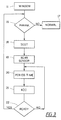
- Fig. 3 shows a typical flow chart for a determination of the buffer capacity.
- a series of input parameters such as engine speed, load, temperature and/or time, are sent to window parameter block 11.
- block 16 it is determined whether the window parameters of any window are fulfilled or not. If they are not fulfilled, block 17 is followed so that the air/fuel ratio continues to be adjusted on the basis of a primary signal from the upstream sensor. This will be the normal situation.
- block 18 indicates that a signal to initiate a test will be sent to selector block 12 in control unit 4.
- This will initiate block 19 which makes the control unit 4 receive the primary control input from input 4b such that fuel injection control is effected by the downstream sensor 3.
- the fluctuations of the signal input at 4b or 4a will then be analyzed (cf. block 20) in order to measure the time period of the fluctuations.
- the signal inputs at inputs 4a and 4b will be analyzed to measure the time displacement between the two signals.
- Block 21 signifies that a determination of oxygen buffer capacity will then be made, this being a function of the analyzed time information, and hence the symbolism K(t).
- a decision is made as to whether the analysis is complete. In the affirmative (YES), the analysis is terminated and the control unit 4 will assume normal operation. If negative (NO), the steps carried out in blocks 20 to 22 will be initiated again.
- Fig. 4 shows typical voltage output signals 23 and 25, and 24 and 26, from the front and rear oxygen sensors respectively, with respect to time (t).
- the lower portion of Fig. 4 shows an output value 27 corresponding to the typical applied factor for fuel injection time and thus how the length of injection timing can vary.
- Zone 20 is a zone in which the engine is running as normal with the primary input from the upstream sensor.
- Zone 21 is the analysis time zone with primary control input from the downstream sensor 3 and zone 22 is when the primary control input is switched back to the upstream sensor 2.
- the output in zone 21 corresponds to a typical output measured over approximately ten seconds, although shorter or longer time zones can be used for zone 21.
- the upstream sensor output 23 fluctuates rapidly which modifies the air/fuel ratio to lean and rich and then back again.
- the downstream sensor 3 output does not fluctuate rapidly but instead supplies a gently varying output to the fuel control unit 4 to richen or weaken the mixture by small increments.
- zone 21 the time period and size of the signal of the downstream sensor output 26 vary relatively rapidly as it alters the inlet mixture from weak to rich and back again.
- the output of the upstream sensor also follows this with a very similar fluctuation waveform, although with a distinct and relatively constant time lag compared to signal 25.
- the period of each of the signals becomes shorter and the time lag becomes less.
- either of these time information sources may be used for the signal analysis.
- zone 22 the output of the two sensors returns to its normal value as in zone 20. A zone similar to zone 21 will then recur when the window parameters are again fulfilled.
- the fluctuating signal 27 shows a value corresponding to the typical applied factor for the injection time. This signal also varies in zone 21 since it is dependent on the resultant input signal from the rear sensor. In this way, the periodic time of the signal 27 in zone 21 can also be used to determine the buffer capacity.
- the signal 27 may have other fluctuation shapes (e.g. square wave form, etc.).
- Fig. 5 shows how the periodic time TP varies with the number of miles driven for a typical catalytic converter.
- TP is almost five seconds whereas with an aged catalytic converter with 200 000 driven miles the time period has been reduced to about half.
- TP reduces with the number of driven miles on an almost linear scale in this particular exhaust system. Since this reduction is due to the reduction in oxygen buffer capacity, a direct comparison can be made with known buffer capacity data in order to determine the present buffer capacity. Different curves will be produced for different vehicles.
- Fig. 6 shows how the periodic time TP varies linearly with mass flow of air or fuel/air into the engine.
- this value can be stored in a memory for subsequent use.
- the fuel injection to the engine can then be modified so that the amount of oxygen buffer capacity never becomes depleted or completely full. This is achieved, for example, by using a short period of weakening and/or richening of the air/fuel mixture at appropriate intervals.
- Richening may be achieved by a small extra quantity of fuel being injected so as to richen the mixture temporarily which will result in more hydrocarbons being passed into the exhaust gases so as to prevent the oxygen in the exhaust gases from filling the entire oxygen buffer capacity.
- the fuel may be injected by, for example, a marginally longer injection period compared to that required.
- mixture weakening can be performed in order to help fill the oxygen buffer capacity if it is being reduced.
- Such buffer corrections will be made on the basis of the determined buffer capacity. Typically these corrections will occur during acceleration or deceleration phases and/or shortly thereafter.
Landscapes
- Engineering & Computer Science (AREA)
- Chemical & Material Sciences (AREA)
- Combustion & Propulsion (AREA)
- Mechanical Engineering (AREA)
- General Engineering & Computer Science (AREA)
- Chemical Kinetics & Catalysis (AREA)
- Electrical Control Of Air Or Fuel Supplied To Internal-Combustion Engine (AREA)
- Exhaust Gas After Treatment (AREA)
- Combined Controls Of Internal Combustion Engines (AREA)
Claims (14)
- Anordnung zum Bestimmen der Sauerstoffpufferkapazität in einem katalytischen Konverter (1) eines Abgassystems, die Anordnung umfasst zumindest einen Downstream-Sauerstoffsensor (3, 32, 3), der downstream von zumindest einer Konvertermatrix (30, 31) des katalytischen Konverters angeordnet ist, der Downstream-Sensor (3, 32, 33) führt ein Eingangssignal (24) einer Kraftstoffeinspritzsteuereinheit (4) zu, und einen Upstream-Sauerstoffsensor (2), der upstream von der Konvertermatrix (30, 31) angeordnet ist, zum Zuführen eines Primäreingangssignals an die Kraftstoffeinspritzsteuereinheit (4), wobei Kraftstoffsteuerungsausgangsmittel innerhalb der Steuereinheit bereitgestellt sind zum Ändern des Luft/Kraftstoff-Verhältnisses in Abhängigkeit von den Eingangssignalen der Downstream- (3, 32, 33) und Upstream- (2) Sensoren,
dadurch gekennzeichnet, dass Mittel (12) bereitgestellt sind, die bewirken, dass das Eingangssignal von dem Downstream-Sensor (3, 32, 33) stattdessen als der Primäreingang von dem Upstream-Sensor für eine beschränkte Zeitperiode wirkt, und dass ein Analysatorschaltkreis (13) bereitgestellt ist zum Bestimmen der Zeitinformation der Fluktuationen des Eingangssignals (26), die daraus resultieren, oder eines fluktuierenden Signals (27), das davon abhängt, und Berechnungsmittel zum Berechnen der Sauerstoffpufferkapazität, basierend auf der Zeitinformation. - Anordnung nach Anspruch 1, dadurch gekennzeichnet, dass ein Schaltmittel (12) bereitgestellt ist zum Schalten des Eingangssignals von dem Downstream-Sensor (3, 32, 33), das stattdessen als der Primäreingang von dem Upstream-Sensor (2) wirkt.
- Anordnung nach einem der Ansprüche 1 oder 2, dadurch gekennzeichnet, dass der Analysatorschaltkreis (13) die Zeitverschiebung der Fluktuationen des Eingangssignals (26) von dem Downstream-Sensor (3, 32, 33) misst bezogen auf die Fluktuationen des Eingangssignals (25) von dem Upstream-Sensor.
- Anordnung nach einem der Ansprüche 1 oder 2, dadurch gekennzeichnet, dass der Analysatorschaltkreis (13) die Zeitperiode (TP) der Fluktuationen in dem/den Eingangssignal(en) (25, 26, 27) misst.
- Anordnung nach einem der Ansprüche 2 bis 4, dadurch gekennzeichnet, dass ein Schaltkreis (1) bereitgestellt ist mit einem Fenster von vorbestimmten Eingangsparametern, die zum Erzeugen eines Ausgangssignals erforderlich sind, und das Ausgangssignal zum Aktivieren der Schaltmittel verwendet wird.
- Anordnung nach einem der vorhergehenden Ansprüche,
dadurch gekennzeichnet, dass die Anordnung des Weiteren Speichermittel zum Speichern des berechneten Wertes der Sauerstoffpufferkapazität umfasst und dass der gespeicherte Wert beim Steuern des Luft-/Kraftstoffmischverhältnisses verwendet wird. - Verfahren zum Bestimmen der Sauerstoffpufferkapazität in einem katalytischen Konverter (1) eines Abgassystems, das System umfasst einen Downstream-Sauerstoffsensor (3, 32, 33), der downstream von einer Konvertermatrix (30, 31) des katalytischen Konverters angeordnet ist, der Downstream-Sensor (3, 32, 33) führt ein Eingangssignal (26) der Kraftstoffeinspritzsteuereinheit (4) zu, und einen Upstream-Sauerstoffsensor (2), der upstream von der Matrix angeordnet ist zum Zuführen eines Primäreingangssignals an die Kraftstoffeinspritzsteuereinheit (4),
dadurch gekennzeichnet, dass das Eingangssignal von dem Downstream-Sensor geschaltet ist, so dass es stattdessen als der Primäreingang von dem Upstream-Sensor (2) für eine beschränkte Zeitperiode wirkt, und dass die resultierenden Fluktuationen in dem Signal von dem Downstream-Sauerstoffsensor (3, 32, 33) oder ein davon abhängiges fluktuierendes Signal (27) analysiert werden, um die Zeitperiode (TP) der Fluktuationen zu bestimmen, und wobei die Sauerstoffpufferkapazität des katalytischen Konverters basierend auf der bestimmten Zeitperiode (TP) berechnet wird. - Verfahren zum Bestimmen der Sauerstoffpufferkapazität in einem katalytischen Konverter (1) eines Abgassystems, das System umfasst einen Downstream-Sauerstoffsensor (3, 32, 33), der downstream von einer Konvertermatrix (30, 31) des katalytischen Konverters angeordnet ist, der Downstream-Sensor (3, 32, 33) führt ein Eingangssignal (26) einer Kraftstoffeinspritzsteuereinheit (4) zu, und ein Upstream-Sauerstoffsensor (2), der upstream von der Matrix angeordnet ist zum Zuführen eines Primäreingangssignals an die Kraftstoffeinspritzsteuereinheit (4),
dadurch gekennzeichnet, dass das Eingangssignal von dem Downstream-Sensor geschaltet wird, so dass es stattdessen als der Primäreingang von dem Upstream-Sensor (2) für eine beschränkte Zeitperiode wirkt, und dass die resultierenden Fluktuationen in dem Signal von dem Downstream-Sauerstoffsensor (3, 32, 33) analysiert werden, um die Zeitverschiebung der Fluktuationen zu bestimmen, und wobei die Sauerstoffpufferkapazität des katalytischen Konverters basierend auf der bestimmten Zeitverschiebung berechnet wird. - Verfahren nach Anspruch 7 oder 8, dadurch gekennzeichnet, dass die Eingangssignale (23, 24, 25, 26) von dem Downstream-Sensor (3, 32, 33) und dem Upstream-Sensor (2) an die Kraftstoffeinspritzsteuereinheit (4) verwendet werden, um das Luft/Kraftstoffverhältnis an der Einlassseite (10) eines Motors zu ändern, und dass die Anordnung des Weiteren Speichermittel zum Speichern des berechneten Wertes der Sauerstoffpufferkapazität umfasst, und dass der gespeicherte Wert beim Steuern des Luft/Kraftstoffverhältnisses verwendet wird.
- Verfahren nach einem der Ansprüche 6 bis 9, dadurch gekennzeichnet, dass ein oder mehrere Fenster von vorbestimmten Parametern innerhalb des Stromkreises der Kraftstoffeinspritzsteuereinheit (4) bereitgestellt sind, und dass die Analyse der Signalfluktuationen nur durchgeführt wird, wenn die Eingangsparameter mit den Parametern innerhalb eines Fensters übereinstimmen.
- Verfahren nach Anspruch 10, dadurch gekennzeichnet, dass die Parameter innerhalb eines Fensters ein oder mehrere der Parameter aus der Gruppe der Parameter umfassen: Massefluss an Kraftstoff zur Einlassseite eines Motors, Massefluss an Luft zur Einlassseite eines Motors, Motorumdrehungsgeschwindigkeit, Motorbelastung, Motortemperatur, Öltemperatur, Temperatur des katalytischen Konverters, Motorlaufzeit, die seit der ursprünglichen Motorzündung vergangen ist, und Motorenlaufzeit seit dem letzten Pufferkapazitätstest.
- Verfahren zum Steuern des Luft-/Kraftstoffverhältnisses eines Fahrzeugmotors basierend auf der Bestimmung der Sauerstoffpufferkapazität nach einem der vorhergehenden Ansprüche 7 bis 11, dadurch gekennzeichnet, dass das Luft-/Kraftstoffverhältnis der in den Motor eingegebenen Mischung geändert wird, um so die zur Verfügung stehende Sauerstoffpufferkapazität zu kompensieren.
- Verfahren nach Anspruch 12, dadurch gekennzeichnet, dass das Luft-/Kraftstoffverhältnis vorübergehend angereichert wird durch Zuführen von Kraftstoff über eine längere Kraftstoffeinspritzzeit als normalerweise erforderlich, um stöchiometrische Bedingungen zu erreichen, oder durch Zuführen einer verschiedenartigen Extramenge an Kraftstoff.
- Verfahren nach Anspruch 12, dadurch gekennzeichnet, dass das Luft-/Kraftstoffverhältnis vorübergehend geschwächt wird durch Zuführen von Kraftstoff über eine kürzere Kraftstoffeinspritzzeit als normalerweise erforderlich, um stöchiometrische Bedingungen zu erreichen, oder durch Zuführen einer geringeren Menge an Kraftstoff.
Applications Claiming Priority (3)
| Application Number | Priority Date | Filing Date | Title |
|---|---|---|---|
| SE9502066 | 1995-06-07 | ||
| SE9502066A SE505235C2 (sv) | 1995-06-07 | 1995-06-07 | Sätt och anordning för att bestämma syrebuffertkapaciteten i en katalytisk avgasrenare |
| PCT/SE1996/000724 WO1996041071A1 (en) | 1995-06-07 | 1996-05-31 | Arrangement and method for determining the oxygen buffer capacity in a catalytic converter |
Publications (2)
| Publication Number | Publication Date |
|---|---|
| EP0830498A1 EP0830498A1 (de) | 1998-03-25 |
| EP0830498B1 true EP0830498B1 (de) | 2001-11-21 |
Family
ID=20398533
Family Applications (1)
| Application Number | Title | Priority Date | Filing Date |
|---|---|---|---|
| EP96918960A Expired - Lifetime EP0830498B1 (de) | 1995-06-07 | 1996-05-31 | Vorrichtung und verfahren zur bestimmung der sauerstoffpufferkapazität in einem katalysator |
Country Status (5)
| Country | Link |
|---|---|
| US (1) | US6119447A (de) |
| EP (1) | EP0830498B1 (de) |
| DE (1) | DE69617232T2 (de) |
| SE (1) | SE505235C2 (de) |
| WO (1) | WO1996041071A1 (de) |
Families Citing this family (26)
| Publication number | Priority date | Publication date | Assignee | Title |
|---|---|---|---|---|
| DE19936200A1 (de) * | 1999-07-31 | 2001-02-08 | Bosch Gmbh Robert | Verfahren zum Betreiben einer Brennkraftmaschine |
| FR2798700B1 (fr) * | 1999-09-21 | 2001-11-23 | Renault | Procede et systeme de surveillance du fonctionnement des pots catalytiques d'un moteur a combustion interne |
| KR100444376B1 (ko) * | 2000-02-16 | 2004-08-16 | 닛산 지도우샤 가부시키가이샤 | 엔진의 배기정화장치 |
| KR100495643B1 (ko) * | 2000-02-25 | 2005-06-14 | 닛산 지도우샤 가부시키가이샤 | 엔진의 배기 정화 장치 |
| US6591605B2 (en) * | 2001-06-11 | 2003-07-15 | Ford Global Technologies, Llc | System and method for controlling the air / fuel ratio in an internal combustion engine |
| US6550237B1 (en) * | 2002-09-25 | 2003-04-22 | Ford Global Technologies, L.L.C. | Method and system for monitoring a catalytic converter |
| US6804951B2 (en) * | 2002-11-06 | 2004-10-19 | Ford Global Technologies, Llc | On-board diagnostic catalyst monitoring system |
| DE102004038481B3 (de) * | 2004-08-07 | 2005-07-07 | Audi Ag | Verfahren zur Regelung des einer Brennkraftmaschine zugeführten Luft/Kraftstoffverhältnisses |
| DE102005004670B4 (de) * | 2005-02-02 | 2007-05-24 | Iav Gmbh Ingenieurgesellschaft Auto Und Verkehr | Verfahren zur Diagnose des Alterungsgrades eines im Abgaskanal einer Brennkraftmaschine angeordneten Katalysators |
| DE102005059894B4 (de) * | 2005-12-15 | 2019-07-25 | Robert Bosch Gmbh | Verfahren zur Messung der Sauerstoffspeicherfähigkeit einer Abgasreinigungsanlage |
| DE102006025050B4 (de) * | 2006-05-27 | 2014-04-03 | Fev Gmbh | Verfahren und Vorrichtung zum Betrieb einer Abgasnachbehandlungsanlage |
| US8666936B2 (en) | 2006-10-05 | 2014-03-04 | Trimble Navigation Limited | System and method for asset management |
| US9747329B2 (en) | 2006-10-05 | 2017-08-29 | Trimble Inc. | Limiting access to asset management information |
| US9747571B2 (en) | 2006-10-05 | 2017-08-29 | Trimble Inc. | Integrated asset management |
| US9519876B2 (en) | 2006-10-05 | 2016-12-13 | Trimble Navigation Limited | Method for providing maintenance to an asset |
| US9811949B2 (en) | 2006-10-05 | 2017-11-07 | Trimble Inc. | Method for providing status information pertaining to an asset |
| US9773222B2 (en) | 2006-10-05 | 2017-09-26 | Trimble Inc. | Externally augmented asset management |
| US9536405B2 (en) | 2006-10-05 | 2017-01-03 | Trimble Inc. | Unreported event status change determination and alerting |
| KR101477582B1 (ko) | 2006-12-07 | 2015-01-02 | 회가내스 아베 | 연자성 분말 |
| US8600932B2 (en) * | 2007-05-07 | 2013-12-03 | Trimble Navigation Limited | Telematic asset microfluidic analysis |
| DE102007059772B4 (de) * | 2007-12-12 | 2014-06-26 | Audi Ag | Verfahren zur Bestimmung der Sauerstoffspeicherkapazität eines Katalysators für ein Kraftfahrzeug sowie zugehörige Messeinrichtung |
| US8165787B2 (en) | 2011-04-08 | 2012-04-24 | Ford Global Technologies, Llc | Method for adjusting engine air-fuel ratio |
| US9760685B2 (en) | 2011-05-16 | 2017-09-12 | Trimble Inc. | Telematic microfluidic analysis using handheld device |
| US9739763B2 (en) * | 2011-05-16 | 2017-08-22 | Trimble Inc. | Telematic locomotive microfluidic analysis |
| JP6971094B2 (ja) * | 2017-08-30 | 2021-11-24 | 日立Astemo株式会社 | 内燃機関の電子制御装置 |
| AT521669B1 (de) * | 2018-08-23 | 2022-08-15 | Avl List Gmbh | Verfahren und Verbrennungskraftmaschine zur Effizienzverbesserung eines SCR-Systems |
Citations (4)
| Publication number | Priority date | Publication date | Assignee | Title |
|---|---|---|---|---|
| EP0466311A1 (de) * | 1990-06-11 | 1992-01-15 | Ford Motor Company Limited | Verfahren zur An-Bord-Feststellung der Degradierung eines Kraftfahrzeugkatalysators |
| US5207057A (en) * | 1991-05-16 | 1993-05-04 | Toyota Jidosha Kabushiki Kaisha | Air-fuel ratio control device for an engine |
| US5293740A (en) * | 1991-08-29 | 1994-03-15 | Robert Bosch Gmbh | Method and arrangement for controlling the quantity of fuel for an internal combustion engine having a catalytic converter |
| US5335538A (en) * | 1991-08-30 | 1994-08-09 | Robert Bosch Gmbh | Method and arrangement for determining the storage capacity of a catalytic converter |
Family Cites Families (17)
| Publication number | Priority date | Publication date | Assignee | Title |
|---|---|---|---|---|
| DE3830515A1 (de) * | 1988-09-08 | 1990-03-22 | Bayerische Motoren Werke Ag | Verfahren zur ueberpruefung der funktion des abgaskatalysators einer brennkraftmaschine |
| US5228335A (en) * | 1991-02-25 | 1993-07-20 | The United States Of America As Represented By The United States Environmental Protection Agency | Method and apparatus for detection of catalyst failure on-board a motor vehicle using a dual oxygen sensor and an algorithm |
| DE4112478C2 (de) * | 1991-04-17 | 2001-03-08 | Bosch Gmbh Robert | Verfahren und Vorrichtung zum Beurteilen des Alterungszustandes eines Katalysators |
| US5159810A (en) * | 1991-08-26 | 1992-11-03 | Ford Motor Company | Catalytic converter monitoring using downstream oxygen sensor |
| US5622047A (en) * | 1992-07-03 | 1997-04-22 | Nippondenso Co., Ltd. | Method and apparatus for detecting saturation gas amount absorbed by catalytic converter |
| JP3010921B2 (ja) * | 1992-08-27 | 2000-02-21 | 日産自動車株式会社 | 内燃機関の触媒劣化診断装置 |
| JPH06129285A (ja) * | 1992-10-20 | 1994-05-10 | Honda Motor Co Ltd | 内燃機関の空燃比制御装置 |
| IT1260234B (it) * | 1992-12-18 | 1996-04-02 | Sistema di controllo a loop chiuso integrato, multifunzione, senza mappatura e auto-adattivo per motori endotermici | |
| JPH06229292A (ja) * | 1993-01-29 | 1994-08-16 | Honda Motor Co Ltd | 内燃機関の空燃比制御装置 |
| FR2702516B1 (fr) * | 1993-03-12 | 1995-06-02 | Siemens Automotive Sa | Procédé de surveillance de l'efficacité d'un pot catalytique chauffé, pour le traitement des gaz d'échappement d'un moteur à combustion interne. |
| DE4308661A1 (de) * | 1993-03-18 | 1994-09-22 | Emitec Emissionstechnologie | Verfahren und Vorrichtung zur Funktionsüberwachung eines katalytischen Konverters |
| GB9315918D0 (en) * | 1993-07-31 | 1993-09-15 | Lucas Ind Plc | Method of and apparatus for monitoring operation of a catalyst |
| JP2858288B2 (ja) * | 1993-09-02 | 1999-02-17 | 株式会社ユニシアジェックス | 内燃機関の空燃比制御装置における自己診断装置 |
| JP2962987B2 (ja) * | 1993-12-01 | 1999-10-12 | 本田技研工業株式会社 | 内燃機関の燃料制御装置 |
| DE59404052D1 (de) * | 1993-12-21 | 1997-10-16 | Siemens Ag | Verfahren zur überprüfung der konvertierungsfähigkeit eines katalysators |
| US5678402A (en) * | 1994-03-23 | 1997-10-21 | Honda Giken Kogyo Kabushiki Kaisha | Air-fuel ratio control system for internal combustion engines and exhaust system temperature-estimating device applicable thereto |
| US5544481A (en) * | 1995-03-31 | 1996-08-13 | Ford Motor Company | Engine air/fuel control system and catalytic converter monitoring |
-
1995
- 1995-06-07 SE SE9502066A patent/SE505235C2/sv unknown
-
1996
- 1996-05-31 US US08/973,174 patent/US6119447A/en not_active Expired - Fee Related
- 1996-05-31 EP EP96918960A patent/EP0830498B1/de not_active Expired - Lifetime
- 1996-05-31 WO PCT/SE1996/000724 patent/WO1996041071A1/en not_active Ceased
- 1996-05-31 DE DE69617232T patent/DE69617232T2/de not_active Expired - Fee Related
Patent Citations (4)
| Publication number | Priority date | Publication date | Assignee | Title |
|---|---|---|---|---|
| EP0466311A1 (de) * | 1990-06-11 | 1992-01-15 | Ford Motor Company Limited | Verfahren zur An-Bord-Feststellung der Degradierung eines Kraftfahrzeugkatalysators |
| US5207057A (en) * | 1991-05-16 | 1993-05-04 | Toyota Jidosha Kabushiki Kaisha | Air-fuel ratio control device for an engine |
| US5293740A (en) * | 1991-08-29 | 1994-03-15 | Robert Bosch Gmbh | Method and arrangement for controlling the quantity of fuel for an internal combustion engine having a catalytic converter |
| US5335538A (en) * | 1991-08-30 | 1994-08-09 | Robert Bosch Gmbh | Method and arrangement for determining the storage capacity of a catalytic converter |
Also Published As
| Publication number | Publication date |
|---|---|
| DE69617232D1 (de) | 2002-01-03 |
| DE69617232T2 (de) | 2002-07-18 |
| EP0830498A1 (de) | 1998-03-25 |
| WO1996041071A1 (en) | 1996-12-19 |
| US6119447A (en) | 2000-09-19 |
| SE9502066D0 (sv) | 1995-06-07 |
| SE505235C2 (sv) | 1997-07-21 |
| SE9502066L (sv) | 1996-12-08 |
Similar Documents
| Publication | Publication Date | Title |
|---|---|---|
| US6119447A (en) | Arrangement and method for determining the oxygen buffer capacity in a catalytic converter | |
| US8141345B2 (en) | Method and device for regulating the fuel/air ratio of a combustion process | |
| EP0136519B1 (de) | Luft/Kraftstoffverhältnissteuereinrichtung für Innenbrennkraftmaschinen | |
| EP0897055B1 (de) | Optimierung der Regelung des Krafstoff/Luft-Verhältnisses einer Brennkraftmaschine unter Verwendung des Sauerstoffspeicherungsvermögens eines Katalysator | |
| US5154055A (en) | Apparatus for detecting purification factor of catalyst | |
| US5335538A (en) | Method and arrangement for determining the storage capacity of a catalytic converter | |
| US5533332A (en) | Method and apparatus for self diagnosis of an internal combustion engine | |
| EP0536789B1 (de) | Vorrichtung zur Bestimmung der Verschlechterung eines Katalysators für eine Brennkraftmaschine | |
| US5207057A (en) | Air-fuel ratio control device for an engine | |
| US7343734B2 (en) | Method for adjusting a defined oxygen concentration by means of binary lambda regulation in order to diagnose an exhaust gas catalyst | |
| EP0547326B1 (de) | Vorrichtung zum Feststellen der Verschlechterung eines Katalysators einer Brennkraftmaschine | |
| US4733358A (en) | Method for optimizing the air/fuel ratio under non-steady conditions in an internal combustion engine | |
| JP3030040B2 (ja) | ラムダ制御方法及び装置 | |
| US4492202A (en) | Fuel injection control | |
| US4580539A (en) | Air-fuel ratio control apparatus | |
| US4693076A (en) | Double air-fuel ratio sensor system having improved response characteristics | |
| US5303580A (en) | Method and arrangement for determining the state of deterioration of a catalyzer | |
| CA1161524A (en) | Closed loop air/fuel ratio control system with oxygen sensor signal compensation | |
| EP0676003B1 (de) | Festellung der verschlechterung eines sauerstoffsensors | |
| JPH06299886A (ja) | フィードバック制御システム及び制御方法 | |
| US6212467B1 (en) | Electronic engine control system | |
| US6644097B2 (en) | Method and apparatus for inferring fuel mixture | |
| JP3195034B2 (ja) | エンジンの排気センサの劣化検出装置 | |
| JPH06185345A (ja) | 車載用触媒コンバータの効率測定方法および装置 | |
| KR20220030891A (ko) | 촉매 컨버터의 모델링된 반응 동특성을 조정하는 방법 및 컴퓨터 유닛 |
Legal Events
| Date | Code | Title | Description |
|---|---|---|---|
| PUAI | Public reference made under article 153(3) epc to a published international application that has entered the european phase |
Free format text: ORIGINAL CODE: 0009012 |
|
| 17P | Request for examination filed |
Effective date: 19971204 |
|
| AK | Designated contracting states |
Kind code of ref document: A1 Designated state(s): DE GB |
|
| 17Q | First examination report despatched |
Effective date: 19990311 |
|
| GRAG | Despatch of communication of intention to grant |
Free format text: ORIGINAL CODE: EPIDOS AGRA |
|
| GRAG | Despatch of communication of intention to grant |
Free format text: ORIGINAL CODE: EPIDOS AGRA |
|
| GRAH | Despatch of communication of intention to grant a patent |
Free format text: ORIGINAL CODE: EPIDOS IGRA |
|
| GRAH | Despatch of communication of intention to grant a patent |
Free format text: ORIGINAL CODE: EPIDOS IGRA |
|
| GRAA | (expected) grant |
Free format text: ORIGINAL CODE: 0009210 |
|
| RAP1 | Party data changed (applicant data changed or rights of an application transferred) |
Owner name: VOLVO CAR CORPORATION |
|
| AK | Designated contracting states |
Kind code of ref document: B1 Designated state(s): DE GB |
|
| REG | Reference to a national code |
Ref country code: GB Ref legal event code: IF02 |
|
| REF | Corresponds to: |
Ref document number: 69617232 Country of ref document: DE Date of ref document: 20020103 |
|
| PLBE | No opposition filed within time limit |
Free format text: ORIGINAL CODE: 0009261 |
|
| STAA | Information on the status of an ep patent application or granted ep patent |
Free format text: STATUS: NO OPPOSITION FILED WITHIN TIME LIMIT |
|
| 26N | No opposition filed | ||
| PGFP | Annual fee paid to national office [announced via postgrant information from national office to epo] |
Ref country code: DE Payment date: 20080530 Year of fee payment: 13 |
|
| PGFP | Annual fee paid to national office [announced via postgrant information from national office to epo] |
Ref country code: GB Payment date: 20080407 Year of fee payment: 13 |
|
| GBPC | Gb: european patent ceased through non-payment of renewal fee |
Effective date: 20090531 |
|
| PG25 | Lapsed in a contracting state [announced via postgrant information from national office to epo] |
Ref country code: GB Free format text: LAPSE BECAUSE OF NON-PAYMENT OF DUE FEES Effective date: 20090531 |
|
| PG25 | Lapsed in a contracting state [announced via postgrant information from national office to epo] |
Ref country code: DE Free format text: LAPSE BECAUSE OF NON-PAYMENT OF DUE FEES Effective date: 20091201 |