EP0829697B1 - Landzielscheibe zum Simulieren von der thermischen Form eines Fahrzeugs wie zum Beispiel eines Panzerfahrzeugs - Google Patents
Landzielscheibe zum Simulieren von der thermischen Form eines Fahrzeugs wie zum Beispiel eines Panzerfahrzeugs Download PDFInfo
- Publication number
- EP0829697B1 EP0829697B1 EP97402109A EP97402109A EP0829697B1 EP 0829697 B1 EP0829697 B1 EP 0829697B1 EP 97402109 A EP97402109 A EP 97402109A EP 97402109 A EP97402109 A EP 97402109A EP 0829697 B1 EP0829697 B1 EP 0829697B1
- Authority
- EP
- European Patent Office
- Prior art keywords
- simulating
- thermal
- support structure
- road train
- vehicle
- Prior art date
- Legal status (The legal status is an assumption and is not a legal conclusion. Google has not performed a legal analysis and makes no representation as to the accuracy of the status listed.)
- Expired - Lifetime
Links
Images

Classifications
-
- F—MECHANICAL ENGINEERING; LIGHTING; HEATING; WEAPONS; BLASTING
- F41—WEAPONS
- F41J—TARGETS; TARGET RANGES; BULLET CATCHERS
- F41J2/00—Reflecting targets, e.g. radar-reflector targets; Active targets transmitting electromagnetic or acoustic waves
- F41J2/02—Active targets transmitting infrared radiation
Definitions
- the present invention relates to a target device terrestrial to simulate the thermal silhouette of an object, including that of a vehicle such as a tank.
- patent FR2716962 which forms a base for the preamble of claim 1, describes a lure of three-dimensional simulation, in particular for a tank, and comprising a supporting structure made from elements metal assemblies on which is laid a canvas camouflage and, in some places, means of heating so as to simulate a thermal signature of the machine.
- patent EP156070 describes a device comprising adjustable thermal emission means covering at least partially a support structure close by its three dimensions of the shape of the vehicle to be simulated, the means thermal emission consisting of modular elements arranged on an intermediate frame, the elements modular being plate-shaped diffusers, at least a heater being associated with the internal face of each Streamer.
- the first is to require the displacement of the observer, or restrictive manipulations of the target to allow the observation of the latter from several angles of observation.
- the patents DE9321080U and US4416456 are known which describe load-bearing structures comprising rolling means and a support on which a target is arranged.
- the carrying structure emits infrared radiation which is added to that of the target and which disturbs it, which harms the quality of the simulation, in particular at the bottom of the target.
- reflections of the infrared radiation occur between each of the different facets of the target which make it difficult to accurately simulate the infrared signature of the object to be simulated.
- thermal targets reproduce only one uniform thermal silhouette by contrast, not allowing to perform variations over a wide temperature range.
- the present invention aims to overcome the disadvantages mentioned above by producing a thermal target easily observable from different viewing angles and which allows a more precise simulation of a silhouette thermal of an object, in particular of a vehicle such as a tank modern whose thermal signature is very little contrasted by in relation to the environment.
- This simulation can be performed both static and dynamic, even on a rugged or muddy terrain.
- the subject of the invention is a device constituting a Earth target to simulate the thermal silhouette of an object mobile as described in claim 1.
- the means of simulation of the thermal silhouette of the undercarriage of the object have at least two frames, the first of which simulates the upper part of the undercarriage of the object and is fixed relative to the supporting structure while the second simulates the lower part of the undercarriage of the object and is able to be moved by means capable of allowing said displacement.
- said means able to allow said displacement are constituted by at at least one actuator, for example of the electrical type or hydraulic.
- the means emissions are made up of modular elements fixed on an intermediate frame, the modular elements can in particular be diffusers in the form of plates, minus one heater being associated with the internal face of each Streamer.
- the thermal emission means are controllable, i.e. controllable according to thermal characteristics of the instantaneous environment of the target.
- the supporting structure has a base for pivoting at least one part of the intermediate structure following a rotation of plus or minus 180 degrees in the horizontal plane.
- the device is further characterized in that a heated train is arranged on each side at the rear of the supporting and resting structure on the ground so as to simulate the tracks of the tracks.
- This train can be attached to the back of the supporting structure and include rolling means.
- the supporting structure includes the means of supply and control of the means thermal emission.
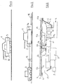
- the thermal target 1 shown in Figure 1 shows a first embodiment for tests without shooting, especially for measurements of infrared silhouettes at for simulation purposes.
- it includes means thermal emission 2, and on the other hand a supporting structure 3 intended to support these means.
- the supporting structure 3 is a vehicle comprising a running gear 31 composed of three pairs of wheels and an intermediate structure, the occurrence of a frame 32 on which the means are fixed thermal emission 2.
- the transmission means thermal 2 have two main parts, a frame and modular elements constituting a skin.
- the frame of the frame consists of tubes 4 of material composite, of the fiberglass profile type for example, for assembly of modular elements. These last are positioned on the frame so as to delimit the contours of the vehicle to represent.
- Modular elements are composed of eight elements main electromechanically homogeneous, corresponding to various structural or functional parts of the vehicle to simulate, namely gun, turret, front and rear parts of the tank, right and left sides, right and left lower parts.
- Each main element is divided into frames, each representing a homogeneous electromechanical entity.
- Each frame is made up of temperature-regulated facets and unregulated facets.
- the number of unregulated facets of the "mask" type concerns only a very small fraction of the surface of the skin, so as to create a contrast by in relation to the regulated background facets, and also to simplify the arrangement of the thermal emission means.
- Each of the temperature-regulated facets consists of diffusers 5 with which are associated, on their internal face 5a, heaters 6 fixed by bonding.
- the diffusers are, for example, aluminum sheets, about 5 mm thick, covered on the external face 5b with a coating 7 of paint, so as to obtain optical characteristics such as a higher reflection coefficient or equal to 0.1 in the visible and near infrared bands and an emissivity greater than 0.9 in the wavelength range between 8 and 12 ⁇ m and for an observation angle less than 60 degrees.
- the choice of such a coating reflecting the solar flux reduces the need for continuous cooling to obtain a set point.
- the specular reflection coefficient must be less than 0.1 in the wavelength range between 8 and 12 ⁇ m and for an observation angle less than 85 degrees.
- the heaters 6 are, in this preferred embodiment, laminar electrical resistances connected in series by conductors 6a, and manufactured to dimensions, the dissipable surface powers of which can vary between 2000 W / m 2 and 6300 W / m 2 .
- the dimensions of the diffusers which correspond to those of the facets, are reduced, for example 40 cm by 40 cm maximum, so as to limit the damage during the impact of a projectile for a configuration of the firing device as described below, and at facilitate repairs.
- the realism of the simulation is also increased, and image degradation thermal impact is limited.
- each heater is connected in 6b to a regulator 8. This is controlled by a control and command unit 9, which is outside the thermal emission means.
- a ventilation group 10 of facets connected in 10a to the regulator, to ensure that necessary cooling of a regulated area in case sudden rise in temperature during regulation.
- This ventilation group consists of fans housed in a panel 11, of the composite material type by example.
- the panel rests in 12 on the frame 4.
- a space 13 about 20 cm lets an air gap between the panel 11 and the diffusers 5, closed at the rear by a sheet 13a, for example aluminum alloy.
- Diffusers and heaters are supported by profiles 4a, resting themselves on panel 11.
- the fans operate all or nothing, extracting and rejecting the heated air under the skin by a sheath of ventilation 14 connected to the outlet of the ventilation group. They are controlled by regulators 8 in conjunction with the control 9.
- regulators 8 in conjunction with the control 9.
- at least one facet regulator so that you can also switch the power for the heaters.
- a postage stamp type temperature probe 15 is glued directly to the internal face of the diffusers, in a area not covered by the heaters.
- the probe is connected in 15a to the regulator so that the information provided by the probe allows instant regulation of heaters.
- the supporting structure is specific and adapted to have dynamic behavior similar to that of the vehicle at simulate, for example a tank.
- the supporting structure is itself a vehicle equipped with a chassis, a driving element, axles and a cockpit.
- the driving element and the cockpit are arranged under the the thickest part corresponding to the turret.
- the chassis is an assembly of mechanically welded profiles so as to integrate all the equipment supports of the vehicle and interface supports with transmission means thermal.
- a heat engine is connected by a drive shaft to a mechanical distribution box which allows sharing the motor power between several hydraulic pumps for propulsion and for the electric generation intended for the means thermal emission.
- the load-bearing structure is a three-axle, six-wheel vehicle independent. All wheels are driven by motor hydraulic, motor-wheel type. So the vehicle is fully hydraulic.
- the imposed turning radius leads to the provision of a mounting of steering to turn the wheels of front and rear axle: the vehicle presented therefore four steered wheels.
- the cockpit interior is isolated from the rest of the vehicle through a metal enclosure. This enclosure is connected grounded and air conditioned.
- the cockpit includes, conventional manner, the conventional driving equipment of motor vehicles.
- the outer cover of the carrier is made of sheet steel polished stainless steel to reduce the thermal silhouette of the vehicle.
- the covers receive the interior side of the vehicle a thermal insulation about 2 cm thick having a very low thermal conductivity. This insulation is covered on the inside of the vehicle with aluminum foil polished.
- the bottom plate of the vehicle is covered on each side a paint with low emissivity.
- the evacuation of the hot cooling gases and of the carrier vehicle is done on its rear side at through a grid inclined downwards, and fitted with fins upward deflection.
- This grid is recessed towards the outside of the vehicle to be at the level of thermal skin emission means.
- the fresh air intake is at the surface less than the front of the vehicle and through all the existing means of thermal emission. Part of this air circulates between diffusers and frame to avoid air pockets hot.
- the air speed through the exchangers is provided by four fans powered by motors hydraulic.
- the thermal emission means are based on the structure carrier: this provides energy and ensures control thermal diffusers through the unit of control and command and provides mobility.
- control and command unit is inserted into the supporting structure and consists of a PC type computer.
- This has software that allows, from the external environment and a mapping, to give the instructions of regulations in order to order the heaters and retrieve the data from temperatures measured by the probes.
- the control and command is able to detect all element failures constituting the device.
- the thermal emission means rest on a frame 3a swivel.
- the structure carrier 3 described above is remotely remote so as not to not be damaged by the shot. This provides energy to thermal emission means and provides thermal control by a network. Means of supply and control independent of the structure could however be used.
- the frame 3a is a wooden frame which has the same bearing surfaces that the supporting structure to receive the means of thermal emission. This frame rests on a base turning which allows it to perform, in the horizontal plane, a rotation of more or less 180 ° with respect to the median axis. The rotation is ensured by electric motors. It is thus possible to present a different view of the target during the flight of the projectile.
- thermal emission means in the form of modules, simulate the running gear of the simulated object so in the track of a tank, and are partly mobile in translation relative to the vehicle chassis.
- this mobility is provided, for each module, by actuators electric or hydraulic fixed at one of their ends to the chassis and to the thermal emission means to the other.
- the operation of the actuators of a module is independent of that of the other modules.
- This mobility of the modules allows for example to simulate crossing an obstacle such as a step or a Pierre...
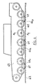
- the thermal emission means 40 simulate a running gear of a tank comprising, for each track 7, carrying rollers, a sprocket and 1 tensioning roller.
- the simulation vehicle comprises 6 driving wheels 41 resting on the ground 42.
- the thermal emission means 40 comprise a first frame 43 fixed relative to the chassis of the vehicle and having a ground clearance of about ten centimeters. They also include a set of three mobile frames 44 1 , 44 2 , 44 3 .
- the simulation of the rollers by the thermal emission means is shown in dotted lines.
- the frame 43 simulates about two thirds of it while the frames 44 1 , 44 2 , 44 3 simulates about a third.
- the mobility of the frame 44 2 is ensured by connecting rods 45 fixed on the one hand to the frame 46 and on the other hand to the frame 44 2 .
- the initial position of the latter is adjusted using a cable 47.
- the cable When it is desired to simulate driving on hard ground on which a tank is not sinking, the cable is relaxed so that the frames 44 1 , 44 2 , 44 3 are flush with the ground.
- the cable is pulled upwards so that the frames 44 1 , 44 2 , 44 3 are completely retracted and that only the heat emission means of the frame 43 emit a infrared signature.
- the retracted position of the frame 44 2 is shown in dotted lines in FIG. 5.
- the frames 44 1 , 44 2 , 44 3 retract one after the other when the step is crossed and then return to the initial position as soon as the step is crossed.
- shock absorbers are arranged on the front of each of them.
- FIG. 6 presents a detailed diagram of the anchoring point of a link on the frame 44 2 .
- the link 45 is constituted by two parallel elements 45 1 , 45 2 having openings facing their lower end.
- a lever 51 comprising an axis 52, free to rotate in said openings, supports a heater 6 and a diffuser 5.
- a rigid suspension system ensures behavior of the simulation vehicle substantially identical to that of a tracked machine, both in pitch and in roll and lace.
- a heated train 16 resting on the ground is arranged on each side behind the device in order to simulate the track of the tracks.
- This train can for example be attached to the supporting structure.
- a mobile target device for firing inert projectile can be envisaged by interposing between the thermal skin or thermal emission means and structure carrier, a subset of protective impact so as to isolate the pilot from the device.
Landscapes
- Engineering & Computer Science (AREA)
- Physics & Mathematics (AREA)
- Electromagnetism (AREA)
- Radar, Positioning & Navigation (AREA)
- Remote Sensing (AREA)
- General Engineering & Computer Science (AREA)
- Aiming, Guidance, Guns With A Light Source, Armor, Camouflage, And Targets (AREA)
- Filling Or Discharging Of Gas Storage Vessels (AREA)
Claims (13)
- Vorrichtung, welche ein für Bodenübungen bestimmtes Trefferziel bildet, zum Simulieren der thermischen Silhouette eines beweglichen Gegenstandes, insbesondere eines Fahrzeugs wie beispielsweise eines Panzers, ausgestattet mit regulierbaren Mitteln (2) für die thermische Emission, welche mindestens teilweise eine Trägerstruktur (3), die in ihren drei Außendimensionen der Form des darzustellenden Gegenstandes ähnlich ist, abdecken, dadurch gekennzeichnet, dass die Trägerstruktur ein Fahrwerk umfaßt, welches insbesondere aus mindestens zwei mit einem Chassis verbundenen Räder-/Achseneinheiten besteht, und dass die Mittel für die thermische Emission (43; 441; 442; 443) mit Mitteln zum Simulieren der thermischen Silhouette des Fahrwerks des Gegenstandes sowie mit Mitteln (45), die das Bewegen von mindestens einem Teil (441; 442; 443) der Mittel zum Simulieren der thermischen Silhouette des Fahrwerks in Bezug auf die Trägerstruktur (3) ermöglichen, ausgestattet sind.
- Vorrichtung gemäß Patentanspruch 1, dadurch gekennzeichnet, dass die Mittel zur Simulation der thermischen Silhouette des Fahrwerks des Gegenstandes mindestens zwei Rahmen (43; 441; 442; 443) umfassen, wobei der erste (43) den oberen Teil des Fahrwerks des Gegenstandes simuliert und im Verhältnis zur Trägerstruktur unbeweglich ist, und der zweite (441; 442; 443) den unteren Teil des Fahrwerks des Gegenstandes simuliert und durch die Mittel (45) bewegt werden kann.
- Vorrichtung gemäß irgendeinem der Patentansprüche 1 und 2, dadurch gekennzeichnet, dass die Mittel (45), die das Bewegen von mindestens einem Teil der besagten Simultationsmittel ermöglichen, mindestens ein Betätigungsglied umfassen.
- Vorrichtung gemäß irgendeinem der Patentansprüche 1 bis 3, dadurch gekennzeichnet, dass die Mittel (45) mindestens einen Schwingarm umfassen.
- Vorrichtung gemäß irgendeinem der Patentansprüche 1 bis 7, dadurch gekennzeichnet, dass die Mittel für die thermische Emission aus auf einer Zwischenarmatur befestigten modularen Elementen bestehen.
- Vorrichtung gemäß Patentanspruch 5, dadurch gekennzeichnet, dass die Form und die Dimensionen der modularen Elemente den verschiedenen strukturellen oder funktionellen Teilen des Gegenstandes entsprechen.
- Vorrichtung gemäß irgendeinem der Patentansprüche 5 und 6, dadurch gekennzeichnet, dass die modularen Elemente plattenförmige Diffusoren (5) sind, wobei mindestens ein Erhitzer (6) mit der Innenseite (5a) eines jeden Diffusors verbunden ist.
- Vorrichtung gemäß Patentanspruch 7, dadurch gekennzeichnet, dass mindestens ein Diffusor einen Reflexionsfaktor von 0,1 oder höher in den sichtbaren Bändern und nahe Infrarot sowie eine Emissionsfähigkeit von über 0,9 im Wellenlängenbereich zwischen 8 und 12 um und für einen Beobachtungswinkel unter 60 Grad aufweist.
- Vorrichtung gemäß Patentanspruch 8, dadurch gekennzeichnet, dass der besagte Diffusor aus einem an der Außenseite 5b mit einer Farbschicht 7 verkleideten Aluminiumblech besteht.
- Vorrichtung gemäß irgendeinem der Patentansprüche 1 bis 9, dadurch gekennzeichnet, dass die Mittel für die thermische Emission steuerbar sind.
- Vorrichtung gemäß Patentanspruch 10, dadurch gekennzeichnet, dass das Fahrzeug mit Versorgungsmitteln (8) und Steuermitteln (9) der Mittel für die thermische Emission ausgestattet ist.
- Vorrichtung gemäß irgendeinem der Patentansprüche 1 bis 11 für die Simulation eines sich auf trockendem Boden fortbewegenden Trägergegenstandes mit Kettenantrieb, dadurch gekennzeichnet, dass sie ein auf jeder Seite hinter der Trägerstruktur angeordnetes heizbares Schleppelement (16) umfasst, um die Spuren der Ketten zu simulieren.
- Vorrichtung gemäß irgendeinem der Patentansprüche 1 bis 12, dadurch gekennzeichnet, dass die Trägerstruktur mit einem Sockel ausgestattet ist, auf welchem die Zwischenarmatur (4), die die Mittel für die thermische Emission trägt, sich entsprechend einer Rotation von mehr oder weniger 180 Grad auf horizontaler Ebene drehen kann.
Applications Claiming Priority (2)
| Application Number | Priority Date | Filing Date | Title |
|---|---|---|---|
| FR9611126 | 1996-09-12 | ||
| FR9611126A FR2753263B1 (fr) | 1996-09-12 | 1996-09-12 | Cible terrestre pour simuler la silhouette thermique d'un vehicule, tel qu'un char |
Publications (3)
| Publication Number | Publication Date |
|---|---|
| EP0829697A2 EP0829697A2 (de) | 1998-03-18 |
| EP0829697A3 EP0829697A3 (de) | 1999-02-17 |
| EP0829697B1 true EP0829697B1 (de) | 2000-05-10 |
Family
ID=9495678
Family Applications (1)
| Application Number | Title | Priority Date | Filing Date |
|---|---|---|---|
| EP97402109A Expired - Lifetime EP0829697B1 (de) | 1996-09-12 | 1997-09-11 | Landzielscheibe zum Simulieren von der thermischen Form eines Fahrzeugs wie zum Beispiel eines Panzerfahrzeugs |
Country Status (4)
| Country | Link |
|---|---|
| US (1) | US5901959A (de) |
| EP (1) | EP0829697B1 (de) |
| DE (1) | DE69701940T2 (de) |
| FR (1) | FR2753263B1 (de) |
Families Citing this family (12)
| Publication number | Priority date | Publication date | Assignee | Title |
|---|---|---|---|---|
| FR2793877B1 (fr) * | 1999-05-18 | 2002-05-17 | Giat Ind Sa | Dispositif de leurrage |
| US7641006B2 (en) * | 2002-06-27 | 2010-01-05 | Scheetz Inc. | Military vehicle with electric drive running gear system |
| US7644788B2 (en) * | 2002-06-27 | 2010-01-12 | Scheetz Inc. | Tensioning and suspension system for a trailer |
| US7325808B1 (en) | 2004-07-29 | 2008-02-05 | Eod Technology, Inc. | Target range systems |
| US9341444B2 (en) | 2005-11-23 | 2016-05-17 | Robert Levine | Thermal electric images |
| US20080134872A1 (en) * | 2005-12-22 | 2008-06-12 | Stuart Owen Goldman | Forced premature detonation of improvised explosive devices via chemical substances |
| US8985585B2 (en) * | 2006-09-11 | 2015-03-24 | Bruce Hodge | Thermal target system |
| US20110175292A1 (en) * | 2008-02-07 | 2011-07-21 | Carni Anthony R | Thermal Signature Target |
| US7939802B2 (en) * | 2008-03-21 | 2011-05-10 | Charlie Grady Guinn | Target with thermal imaging system |
| US7820969B2 (en) * | 2008-03-21 | 2010-10-26 | Charlie Grady Guinn | Target with thermal imaging system |
| CA2723481C (en) * | 2008-05-05 | 2015-08-04 | R.A.S.R. Thermal Target Systems Inc. | Reactive firearm training target |
| US20220276028A1 (en) * | 2019-08-21 | 2022-09-01 | Marathon Robotics Pty Ltd | A Target for Use in Firearms Training |
Family Cites Families (12)
| Publication number | Priority date | Publication date | Assignee | Title |
|---|---|---|---|---|
| US4416456A (en) * | 1978-12-08 | 1983-11-22 | Australasian Training Aids Pty. Ltd. | Trolleys for target ranges |
| US4306630A (en) * | 1979-02-01 | 1981-12-22 | Monte Anthony J | Radio controlled miniature target vehicle and radio control accessory for binoculars |
| US4240212A (en) * | 1979-06-21 | 1980-12-23 | The United States Of America As Represented By The Secretary Of The Navy | Thermal signature targets |
| US4253670A (en) * | 1979-08-07 | 1981-03-03 | The United States Of America As Represented By The Secretary Of The Army | Simulated thermal target |
| US4546983A (en) * | 1981-09-18 | 1985-10-15 | Tvi Energy Corporation | Multi-spectral target |
| US4515374A (en) * | 1983-11-21 | 1985-05-07 | Herren Jr Thomas W | Moveable target assembly |
| DE3516392A1 (de) * | 1984-10-30 | 1986-11-13 | Carlheinz 8484 Grafenwöhr Geuss | Zielflaeche zur verwendung bei einer zieleinrichtung fuer infrarot-schiessuebungen |
| US4946171A (en) * | 1989-01-03 | 1990-08-07 | Eastman Kodak Company | Live fire target modular support structure |
| US5065032A (en) * | 1990-09-10 | 1991-11-12 | Custom Training Aids | Thermal integrated target |
| DE9321080U1 (de) * | 1992-12-23 | 1996-01-18 | Mey, Klaus-Peter, Dipl.-Ing. Dipl.-Wirtsch.-Ing. Dr.-Ing., 50226 Frechen | Zielobjekt, insbesondere Zielscheibe mit Halterung |
| FR2716962B1 (fr) * | 1994-03-07 | 1996-05-24 | Bachmann Camouflage Sa | Leurre de simulation notamment d'un engin de combat. |
| DE4425635C1 (de) * | 1994-07-20 | 1995-11-23 | Daimler Benz Aerospace Ag | Selbstfahrmodul |
-
1996
- 1996-09-12 FR FR9611126A patent/FR2753263B1/fr not_active Expired - Fee Related
-
1997
- 1997-09-11 EP EP97402109A patent/EP0829697B1/de not_active Expired - Lifetime
- 1997-09-11 DE DE69701940T patent/DE69701940T2/de not_active Expired - Fee Related
- 1997-09-12 US US08/928,754 patent/US5901959A/en not_active Expired - Fee Related
Also Published As
| Publication number | Publication date |
|---|---|
| US5901959A (en) | 1999-05-11 |
| FR2753263A1 (fr) | 1998-03-13 |
| DE69701940T2 (de) | 2000-10-05 |
| DE69701940D1 (de) | 2000-06-15 |
| EP0829697A2 (de) | 1998-03-18 |
| EP0829697A3 (de) | 1999-02-17 |
| FR2753263B1 (fr) | 1998-10-30 |
Similar Documents
| Publication | Publication Date | Title |
|---|---|---|
| EP0829697A2 (de) | Landzielscheibe zum Simulieren von der thermischen Form eines Fahrzeugs wie zum Beispiel eines Panzerfahrzeugs | |
| CA3022169A1 (fr) | Vehicule electrique terrestre de transport en commun, muni de capot(s) de protection des batteries | |
| EP1035017B1 (de) | Verfahren für die Simulation der äusseren Wärmeströme, die von den Abstrahlelementen eines Raumfahrzeuges während des Fluges absorbiert werden, und Raumfahrzeug für die Durchführung dieses Verfahrens | |
| EP2196762A1 (de) | Rollendes Material zum Auslösen von Sprengladungen und motorisierte Einheit zum Sichern von Straßen, Pisten und Ähnlichem | |
| FR2930234A1 (fr) | Systeme de degivrage et/ou d'antigivrage pour bord d'attaque de voilure d'aeronef. | |
| FR2818916A1 (fr) | Appareil et procede d'attraction | |
| FR2553596A1 (fr) | Systeme d'actionnement d'helice de moteur | |
| FR2916528A1 (fr) | Vehicule blinde leger modulaire et cabine mise en oeuvre dans un tel vehicule | |
| WO2020065071A1 (fr) | Véhicule motorisé | |
| EP2857821B1 (de) | Prüfvorrichtung für Kraftfahrzeuge | |
| WO2018189259A1 (fr) | Dispositif de déploiement | |
| EP1054230B1 (de) | Täuscheinrichtung zum Irreführen einer Landmine | |
| FR2523220A1 (fr) | Centrale eolienne pour la production d'energie | |
| EP4363779B1 (de) | Reinigungsroboter für ein solarkraftwerk | |
| FR2509801A1 (fr) | Module stato-eolien parasonore | |
| WO2018197780A1 (fr) | Dispositif de chauffage pour un véhicule automobile | |
| FR3077267A1 (fr) | Aerodyne sans pilote | |
| FR3136835A1 (fr) | Générateur d’air réversible mobile pour le conditionnement thermique des constructions légères, permanentes ou éphémères | |
| FR2641853A1 (fr) | Dispositif de refroidissement de l'air par la technique d'evaporation | |
| FR2723190A1 (fr) | Banc de simulation infra-rouge | |
| EP1006334B1 (de) | Wärmeziel | |
| FR2547029A1 (fr) | Procedes de domestication des energies solaire et eolienne | |
| FR2970485A1 (fr) | Dispositif mobile de traitement des pistes d'aerodrome ou point strategique par temps de neige ou pluie verglacante par projection d'air chaud comprime | |
| FR3136792A1 (fr) | Fondoir pour mastic bitumineux, remorque comportant le fondoir | |
| WO2013160623A2 (fr) | Radiateur electrique dont la face interne de la facade avant presente des zones ayant des emissivites differentes |
Legal Events
| Date | Code | Title | Description |
|---|---|---|---|
| PUAI | Public reference made under article 153(3) epc to a published international application that has entered the european phase |
Free format text: ORIGINAL CODE: 0009012 |
|
| 17P | Request for examination filed |
Effective date: 19971002 |
|
| AK | Designated contracting states |
Kind code of ref document: A2 Designated state(s): DE FR GB IT NL |
|
| AX | Request for extension of the european patent |
Free format text: AL;LT;LV;RO;SI |
|
| PUAL | Search report despatched |
Free format text: ORIGINAL CODE: 0009013 |
|
| AK | Designated contracting states |
Kind code of ref document: A3 Designated state(s): AT BE CH DE DK ES FI FR GB GR IE IT LI LU MC NL PT SE |
|
| AX | Request for extension of the european patent |
Free format text: AL;LT;LV;RO;SI |
|
| 17Q | First examination report despatched |
Effective date: 19990512 |
|
| GRAG | Despatch of communication of intention to grant |
Free format text: ORIGINAL CODE: EPIDOS AGRA |
|
| GRAG | Despatch of communication of intention to grant |
Free format text: ORIGINAL CODE: EPIDOS AGRA |
|
| GRAH | Despatch of communication of intention to grant a patent |
Free format text: ORIGINAL CODE: EPIDOS IGRA |
|
| AKX | Designation fees paid |
Free format text: DE FR GB IT NL |
|
| GRAH | Despatch of communication of intention to grant a patent |
Free format text: ORIGINAL CODE: EPIDOS IGRA |
|
| GRAA | (expected) grant |
Free format text: ORIGINAL CODE: 0009210 |
|
| AK | Designated contracting states |
Kind code of ref document: B1 Designated state(s): DE FR GB IT NL |
|
| ITF | It: translation for a ep patent filed | ||
| REF | Corresponds to: |
Ref document number: 69701940 Country of ref document: DE Date of ref document: 20000615 |
|
| GBT | Gb: translation of ep patent filed (gb section 77(6)(a)/1977) |
Effective date: 20000602 |
|
| PLBE | No opposition filed within time limit |
Free format text: ORIGINAL CODE: 0009261 |
|
| STAA | Information on the status of an ep patent application or granted ep patent |
Free format text: STATUS: NO OPPOSITION FILED WITHIN TIME LIMIT |
|
| 26N | No opposition filed | ||
| PGFP | Annual fee paid to national office [announced via postgrant information from national office to epo] |
Ref country code: DE Payment date: 20011130 Year of fee payment: 5 |
|
| REG | Reference to a national code |
Ref country code: GB Ref legal event code: IF02 |
|
| PGFP | Annual fee paid to national office [announced via postgrant information from national office to epo] |
Ref country code: FR Payment date: 20020327 Year of fee payment: 5 |
|
| PGFP | Annual fee paid to national office [announced via postgrant information from national office to epo] |
Ref country code: GB Payment date: 20020830 Year of fee payment: 6 |
|
| PGFP | Annual fee paid to national office [announced via postgrant information from national office to epo] |
Ref country code: NL Payment date: 20020930 Year of fee payment: 6 |
|
| PG25 | Lapsed in a contracting state [announced via postgrant information from national office to epo] |
Ref country code: DE Free format text: LAPSE BECAUSE OF NON-PAYMENT OF DUE FEES Effective date: 20030401 |
|
| PG25 | Lapsed in a contracting state [announced via postgrant information from national office to epo] |
Ref country code: FR Free format text: LAPSE BECAUSE OF NON-PAYMENT OF DUE FEES Effective date: 20030603 |
|
| REG | Reference to a national code |
Ref country code: FR Ref legal event code: ST |
|
| PG25 | Lapsed in a contracting state [announced via postgrant information from national office to epo] |
Ref country code: GB Free format text: LAPSE BECAUSE OF NON-PAYMENT OF DUE FEES Effective date: 20030911 |
|
| PG25 | Lapsed in a contracting state [announced via postgrant information from national office to epo] |
Ref country code: NL Free format text: LAPSE BECAUSE OF NON-PAYMENT OF DUE FEES Effective date: 20040401 |
|
| GBPC | Gb: european patent ceased through non-payment of renewal fee |
Effective date: 20030911 |
|
| NLV4 | Nl: lapsed or anulled due to non-payment of the annual fee |
Effective date: 20040401 |
|
| PG25 | Lapsed in a contracting state [announced via postgrant information from national office to epo] |
Ref country code: IT Free format text: LAPSE BECAUSE OF NON-PAYMENT OF DUE FEES Effective date: 20050911 |