EP0828102A2 - Steam turbine control - Google Patents
Steam turbine control Download PDFInfo
- Publication number
- EP0828102A2 EP0828102A2 EP97114903A EP97114903A EP0828102A2 EP 0828102 A2 EP0828102 A2 EP 0828102A2 EP 97114903 A EP97114903 A EP 97114903A EP 97114903 A EP97114903 A EP 97114903A EP 0828102 A2 EP0828102 A2 EP 0828102A2
- Authority
- EP
- European Patent Office
- Prior art keywords
- valve
- cone
- insert
- hydraulic drive
- steam
- Prior art date
- Legal status (The legal status is an assumption and is not a legal conclusion. Google has not performed a legal analysis and makes no representation as to the accuracy of the status listed.)
- Granted
Links
Images

Classifications
-
- F—MECHANICAL ENGINEERING; LIGHTING; HEATING; WEAPONS; BLASTING
- F01—MACHINES OR ENGINES IN GENERAL; ENGINE PLANTS IN GENERAL; STEAM ENGINES
- F01D—NON-POSITIVE DISPLACEMENT MACHINES OR ENGINES, e.g. STEAM TURBINES
- F01D17/00—Regulating or controlling by varying flow
- F01D17/10—Final actuators
- F01D17/12—Final actuators arranged in stator parts
- F01D17/14—Final actuators arranged in stator parts varying effective cross-sectional area of nozzles or guide conduits
- F01D17/141—Final actuators arranged in stator parts varying effective cross-sectional area of nozzles or guide conduits by means of shiftable members or valves obturating part of the flow path
- F01D17/145—Final actuators arranged in stator parts varying effective cross-sectional area of nozzles or guide conduits by means of shiftable members or valves obturating part of the flow path by means of valves, e.g. for steam turbines
-
- F—MECHANICAL ENGINEERING; LIGHTING; HEATING; WEAPONS; BLASTING
- F16—ENGINEERING ELEMENTS AND UNITS; GENERAL MEASURES FOR PRODUCING AND MAINTAINING EFFECTIVE FUNCTIONING OF MACHINES OR INSTALLATIONS; THERMAL INSULATION IN GENERAL
- F16K—VALVES; TAPS; COCKS; ACTUATING-FLOATS; DEVICES FOR VENTING OR AERATING
- F16K31/00—Actuating devices; Operating means; Releasing devices
- F16K31/12—Actuating devices; Operating means; Releasing devices actuated by fluid
Definitions
- the invention relates to a steam control valve for Steam turbines with one arranged in the valve housing Valve insert, with one in a packing guided valve spindle, with one in the valve insert sliding valve cone and with one in the valve housing arranged valve diffuser and a hydraulic Drive.
- Pressure-balanced steam control valves are known for Steam turbines used as single or double seat valves be carried out by means of oil hydraulic Drives are operated.
- the double seat valve is due to the back to back arrangement two valve plates or cones pressure-balanced, so that due to the minimum differential pressure no appreciable opening forces on the valve the vapor pressure when the valve is closed arise.
- the double seat valve is, however, for technical reasons almost never tight. On the one hand, this is due to the constructive Uncertainty when dimensioning the distance of the two valve seats and the other on the not exactly the same thermal expansion of the valve housing and Valve stem with the two integral valve disks.
- the cross-sectional area falls to the rear of the valve cone the valve stem for a complete one Pressure equalization gone.
- the Cross section of the valve stem is smaller than for a valve without pressure compensation. Because of that The closing spring can also have a lower spindle lift can be installed with lower preload. This means, as with the double seat valve, the required Forces to operate the valve are low.
- valve cone designed as a piston is necessary against the valve insert designed as a sleeve sealed.
- valves and actuators must be located below the turbine; or, that when the valves are arranged above the turbine hydraulic drives via levers and redirections their Function.
- the object of the invention is to provide a steam control valve develop, which requires minimal adjustment forces and is sealed when closed and what inclusive its drive arranged above the turbine can, without, as with oil hydraulic Given drives, the risk of an oil fire arises.
- valve including its hydraulic Drive can be arranged in any installation position can, so even in a hanging position below the Turbine.
- the valve consists of a valve cone, the one with two or more axial bores is provided so that below and above the valve cone the pressure is always the same.
- the valve cone is guided in a valve insert and with upper and lower piston rings against this sealed.
- valve cone diameters above and below are like this dimensioned that the upper steam-loaded cone surface taking into account the spindle cross section of the Area corresponds to the underside of the cone.
- the valve cone is thus in terms of top and bottom balancing pressure forces acting on it. As a result of this balance, the adjusting forces for the valve small, so that the spindle diameter can be kept small.
- the spindle is with one Gland packing sealed against the valve insert.
- valve plug To avoid steam leakage when closed Control valve (the valve plug sits on the valve diffuser on) via the piston rings and the axial Bores is the valve plug with one turn provided, which with the upper and lower valve insert forms a chamber. This chamber becomes over one or more channels arranged in the valve insert are, leakage vapor to an atmospheric or aspirated lower pressure level.
- valve insert is divided into two.
- Both parts of the valve insert are telescopic put together.
- the valve is operated by a hydraulic Drive.
- a key feature of the present Invention is the use of clear water as a hydraulic fluid to drive the steam control valve. With this version of the drive is environmental protection and fire protection is easily done.
- the invention is based on a schematic Embodiment explained in more detail.
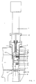
- Fig. 1 shows a section through the control valve with attached water hydraulic drive (7) and Drive lantern (15).
- the valve stem (5) of the Valve plug (1) is sealed by a packing (12) guided in the upper part of the valve insert (3a) is arranged.
- valve insert (3a and 3b) and the valve diffuser (6) are detachably fastened in the valve housing (10).
- the lower part of the valve insert (3b) protrudes into the Steam room (11).
- the valve insert (3) is in two parts executed, it consists of the upper part (3a) and the lower part (3b), which are pushed into each other and are screwed.
- valve cone (1) slides through three piston rings each (4) sealed, in the valve insert parts (3a) and (3b).
- the nested valve insert parts (3a) and (3b) form at their separation point by means of longitudinal grooves and Screwing the upper part (3a) a flow channel (9), which is designed as a suction channel for leakage steam and on a suction line (17) is connected.
- valve cone (1) In the valve cone (1) are continuous axial Bores (2) introduced. Above the valve cone (1) forms a chamber (16) through which Bores (2) is exposed to steam.
- valve cone (1) By turning the valve cone (1) in the middle Area (1b) forms between valve cone (1) and Valve insert (3a and 3b) a chamber (8) to which a Suction channel (9) is connected.
- Fig. 2 shows a section on an enlarged scale through the control valve, but without the water hydraulic Drive.
- the valve insert (3a and 3b) in the Valve housing (10) is hatched here shown.
- valve cone (1) is on a valve spindle (5) attached. Both the top (14) and the bottom (13) The surface of the valve cone (1a) and (1c) are pressurized. The lower pressurized surface (13) closes with the when the valve is closed Valve diffuser (6), which is inserted into the valve housing (10) is, from.
- Fig. 2 The other features of Fig. 2 are identical to Fig. 1.
Abstract
Description
Die Erfindung betrifft ein Dampfstellventil für Dampfturbinen mit einem im Ventilgehäuse angeordneten Ventileinsatz, mit einer in einer Dichtungspackung geführten Ventilspindel, mit einem im Ventileinsatz gleitenden Ventilkegel und mit einem im Ventilgehäuse angeordneten Ventildiffusor und einem hydraulischen Antrieb.The invention relates to a steam control valve for Steam turbines with one arranged in the valve housing Valve insert, with one in a packing guided valve spindle, with one in the valve insert sliding valve cone and with one in the valve housing arranged valve diffuser and a hydraulic Drive.
Bekannt sind druckausgeglichene Dampf-Stellventile für Dampfturbinen, die als Einfach- oder Doppelsitzventile ausgeführt werden und die mittels ölhydraulischer Antriebe betätigt werden.Pressure-balanced steam control valves are known for Steam turbines used as single or double seat valves be carried out by means of oil hydraulic Drives are operated.
Das Doppelsitzventil ist infolge der Rücken an Rücken-Anordnung zweier Ventilteller oder -kegel druckausgeglichen, so daß infolge des minimalen Differenzdrucks auf das Ventil keine nennenswerten Öffnungskräfte aus dem Dampfdruck in geschlossenem Zustand des Ventils entstehen.The double seat valve is due to the back to back arrangement two valve plates or cones pressure-balanced, so that due to the minimum differential pressure no appreciable opening forces on the valve the vapor pressure when the valve is closed arise.
Da somit die hydraulischen Antriebe kleiner ausfallen können, ist auch die Kraft für die Ölverdrängung beim Schließvorgang geringer, und da wegen der geringeren Verstellkräfte auch der Querschnitt der Ventilspindel geringer ausfallen kann, ist auch der Spindelauftrieb in geöffnetem Zustand des Ventils geringer und die Vorspannung der Schließfeder kann geringer ausfallen. Das heißt, die notwendigen Kräfte zur Betätigung eines Doppelsitzventils sind relativ gering.Because the hydraulic drives are smaller is also the force for oil displacement in the Closing process less, and because of the lower Adjustment forces also the cross section of the valve spindle spindle lift can also be lower lower when the valve is open and the Preload of the closing spring can be less. That means the necessary forces to operate a Double seat valves are relatively small.
Das Doppelsitzventil ist aus technischen Gründen jedoch fast nie dicht. Dies liegt zum einen an der konstruktiven Überbestimmtheit bei der Bemaßung des Abstandes der beiden Ventilsitze und zum anderen an der nicht exakt gleichen Wärmeausdehnung von Ventilgehäuse und Ventilspindel mit den zwei integralen Ventiltellern. The double seat valve is, however, for technical reasons almost never tight. On the one hand, this is due to the constructive Uncertainty when dimensioning the distance of the two valve seats and the other on the not exactly the same thermal expansion of the valve housing and Valve stem with the two integral valve disks.
Bei dem bekannten Einfachsitzventil in Kolbenbauweise wird wie bei der vorliegenden Erfindung die Rückseite des Ventils mit dem gleichen Druck beaufschlagt, wie er in Strömungsrichtung gesehen hinter dem Ventil herrscht.In the known single-seat valve in piston design becomes the back as in the present invention of the valve is pressurized with the same pressure as it is seen behind the valve in the direction of flow prevails.
Durch die notwendige Anbindung der Ventilspindel auf der Rückseite des Ventilkegels fällt die Querschnittsfläche der Ventilspindel jedoch für einen vollständigen Druckausgleich weg. Wie beim Doppelsitzventil kann der Querschnitt der Ventilspindel geringer ausfallen als bei einem Ventil ohne Druckausgleich. Wegen des somit geringeren Spindelauftriebs kann auch die Schließfeder mit geringerer Vorspannung eingebaut werden. Das heißt, wie beim Doppelsitzventil sind die erforderlichen Kräfte zur Betätigung des Ventils gering.Due to the necessary connection of the valve spindle the cross-sectional area falls to the rear of the valve cone the valve stem for a complete one Pressure equalization gone. As with the double seat valve, the Cross section of the valve stem is smaller than for a valve without pressure compensation. Because of that The closing spring can also have a lower spindle lift can be installed with lower preload. This means, as with the double seat valve, the required Forces to operate the valve are low.
Der als Kolben ausgeführte Ventilkegel ist notwendigerweise gegen den als Büchse ausgeführten Ventileinsatz abgedichtet. Die Dampfleckage über diesen Dichtring (Dichtringe) fließt jedoch über die Druckausgleichsbohrungen im Ventilkegel der Beschaufelung der Turbine zu. Dieses kann bei hohen Dampfdrücken zu einem ungewollten Anlaufen der Turbine führen.The valve cone designed as a piston is necessary against the valve insert designed as a sleeve sealed. The steam leak over this sealing ring (Sealing rings), however, flows through the pressure compensation holes in the valve cone of the turbine blades to. At high steam pressures, this can lead to an unwanted Start the turbine.
Die ölhydraulischen Antriebe der genannten Dampf-Stellventile werden aus Gründen des Brandschutzes heute immer außerhalb des Bereiches heißer Turbinenteile angeordnet. Das heißt, daß Ventile und Antriebe unterhalb der Turbine angeordnet werden müssen; oder, daß bei Anordnung der Ventile oberhalb der Turbine die hydraulischen Antriebe über Hebel und Umlenkungen ihre Funktion erfüllen müssen.The oil-hydraulic drives of the steam control valves mentioned are used for fire safety reasons today always outside the area of hot turbine parts arranged. That means valves and actuators must be located below the turbine; or, that when the valves are arranged above the turbine hydraulic drives via levers and redirections their Function.
Aufgabe der Erfindung ist es, ein Dampf-Stellventil zu entwickeln, welches minimale Verstellkräfte erfordert und in geschlossenem Zustand dicht ist und was einschließlich seines Antriebs oberhalb der Turbine angeordnet werden kann, ohne daß, wie bei ölhydraulischen Antrieben gegeben, die Gefahr eines Ölbrandes entsteht.The object of the invention is to provide a steam control valve develop, which requires minimal adjustment forces and is sealed when closed and what inclusive its drive arranged above the turbine can, without, as with oil hydraulic Given drives, the risk of an oil fire arises.
Weiterhin soll das Ventil einschließlich seines hydraulischen Antriebs in jeder Einbaulage angeordnet werden können, also auch in hängender Lage unterhalb der Turbine.Furthermore, the valve including its hydraulic Drive can be arranged in any installation position can, so even in a hanging position below the Turbine.
Die Lösung der Aufgabe erfolgt entsprechend dem
kennzeichnenden Merkmal von Anspruch 1. Die Unteransprüche
stellen eine vorteilhafte Ausgestaltung der
Erfindung dar.The task is solved accordingly
characteristic feature of
Erfindungsgemäß besteht das Ventil aus einem Ventilkegel, der mit zwei oder mehreren axialen Bohrungen versehen ist, so daß unterhalb und oberhalb des Ventilkegels jeweils der gleiche Druck herrscht. Der Ventilkegel wird in einem Ventileinsatz geführt und mit oberen und unteren Kolbenringen gegen diesen abgedichtet.According to the invention, the valve consists of a valve cone, the one with two or more axial bores is provided so that below and above the valve cone the pressure is always the same. The valve cone is guided in a valve insert and with upper and lower piston rings against this sealed.
Die Ventilkegeldurchmesser oben und unten sind so bemessen, daß die obere dampfbeaufschlagte Kegelfläche unter Berücksichtigung des Spindelquerschnitts der Fläche der Kegelunterseite entspricht. Der Ventilkegel befindet sich somit hinsichtlich der von oben und unten auf ihn einwirkenden Druckkräfte im Gleichgewicht. Infolge dieses Gleichgewichts sind die Verstellkräfte für das Ventil gering, so daß der Spindeldurchmesser klein gehalten werden kann. Die Spindel ist mit einer Stopfbuchspackung gegen den Ventileinsatz abgedichtet.The valve cone diameters above and below are like this dimensioned that the upper steam-loaded cone surface taking into account the spindle cross section of the Area corresponds to the underside of the cone. The valve cone is thus in terms of top and bottom balancing pressure forces acting on it. As a result of this balance, the adjusting forces for the valve small, so that the spindle diameter can be kept small. The spindle is with one Gland packing sealed against the valve insert.
Die zu überwindenden Kräfte beim Verstellvorgang des Stellventils resultieren nur aus der Reibung der Kolbenringe und der wegen des geringen Spindeldurchmessers geringen Reibung in der Stopfbuchspackung und einer in Schließrichtung wirkenden Feder, die in oder unterhalb des Hydraulikantriebs angeordnet sein kann sowie letztendlich aus dem Auftrieb, der aus dem Druck in der ringförmigen Absaugkammer auf die unterschiedlichen kammerbildenden Ringflächen des Ventilkegels in Verbindung mit dem Ventileinsatz herrührt.The forces to be overcome when adjusting the Control valve result only from the friction of the Piston rings and because of the small spindle diameter low friction in the gland packing and a spring acting in the closing direction, which in or can be arranged below the hydraulic drive and ultimately from the buoyancy, from the pressure in the annular suction chamber to the different chamber-forming annular surfaces of the valve cone in Connection with the valve insert.
Zur Vermeidung von Dampfleckagen bei geschlossenem Stellventil (der Ventilkegel sitzt auf dem Ventildiffusor auf) über die Kolbenringe und die axialen Bohrungen ist der Ventilkegel mit einer Eindrehung versehen, welche mit dem oberen und unteren Ventileinsatz eine Kammer bildet. Aus dieser Kammer wird über einen oder mehrere Kanäle, die im Ventileinsatz angeordnet sind, Leckagedampf zu einem atmosphärischen oder niedrigeren Druckniveau hin abgesaugt.To avoid steam leakage when closed Control valve (the valve plug sits on the valve diffuser on) via the piston rings and the axial Bores is the valve plug with one turn provided, which with the upper and lower valve insert forms a chamber. This chamber becomes over one or more channels arranged in the valve insert are, leakage vapor to an atmospheric or aspirated lower pressure level.
Um den Einbau des Ventilkegels in den Ventileinsatz zu ermöglichen, ist der Ventileinsatz zweigeteilt. Die beiden Teile des Ventileinsatzes sind teleskopähnlich zusammengesteckt.To install the valve cone in the valve insert allow, the valve insert is divided into two. The Both parts of the valve insert are telescopic put together.
Betätigt wird das Ventil mittels eines hydraulischen Antriebes. Ein entscheidendes Merkmal der vorliegenden Erfindung ist der Einsatz von Klarwasser als Hydraulikflüssigkeit zum Antrieb des Dampfstellventils. Mit dieser Ausführung des Antriebes wird dem Umweltschutz und dem Brandschutz auf einfache Weise genüge getan.The valve is operated by a hydraulic Drive. A key feature of the present Invention is the use of clear water as a hydraulic fluid to drive the steam control valve. With this version of the drive is environmental protection and fire protection is easily done.
Für Anlagen, die Minustemperaturen ausgesetzt sind, wird dem Klarwasser ein handelsübliches Frostschutzmittel zugesetzt.For systems that are exposed to sub-zero temperatures clear water becomes a commercially available antifreeze added.
Die Erfindung wird anhand eines schematischen Ausführungsbeispiels näher erläutert. The invention is based on a schematic Embodiment explained in more detail.
Es zeigen:
- Fig. 1
- einen Schnitt durch das Stellventil mit Hydraulikantrieb,
- Fig. 2
- einen vergrößerten Schnitt durch das Stellventil.
- Fig. 1
- a section through the control valve with hydraulic drive,
- Fig. 2
- an enlarged section through the control valve.
Fig. 1 zeigt einen Schnitt durch das Stellventil mit aufgesetztem wasserhydraulischen Antrieb (7) und der Antriebslaterne (15). Die Ventilspindel (5) des Ventilkegels (1) wird durch eine Dichtungspackung (12) geführt, die im Oberteil des Ventileinsatzes (3a) angeordnet ist.Fig. 1 shows a section through the control valve with attached water hydraulic drive (7) and Drive lantern (15). The valve stem (5) of the Valve plug (1) is sealed by a packing (12) guided in the upper part of the valve insert (3a) is arranged.
Der Ventileinsatz (3a und 3b) und der Ventildiffusor (6) sind im Ventilgehäuse (10) lösbar befestigt. Der untere Teil des Ventileinsatzes (3b) ragt in den Dampfraum (11) hinein. Der Ventileinsatz (3) ist zweiteilig ausgeführt, er besteht aus dem Oberteil (3a) und dem Unterteil (3b), die ineinandergeschoben werden und verschraubt sind.The valve insert (3a and 3b) and the valve diffuser (6) are detachably fastened in the valve housing (10). The lower part of the valve insert (3b) protrudes into the Steam room (11). The valve insert (3) is in two parts executed, it consists of the upper part (3a) and the lower part (3b), which are pushed into each other and are screwed.
Der Ventilkegel (1) gleitet, durch jeweils drei Kolbenringe (4) abgedichtet, in den Ventileinsatzteilen (3a) und (3b).The valve cone (1) slides through three piston rings each (4) sealed, in the valve insert parts (3a) and (3b).
Die ineinandergeschobenen Ventileinsatzteile (3a) und (3b) bilden an ihrer Trennstelle mittels Längsnuten und Eindrehung des Oberteils (3a) einen Strömungskanal (9), der als Absaugkanal für Leckagedampf ausgebildet und an eine Absaugeleitung (17) angeschlossen ist. The nested valve insert parts (3a) and (3b) form at their separation point by means of longitudinal grooves and Screwing the upper part (3a) a flow channel (9), which is designed as a suction channel for leakage steam and on a suction line (17) is connected.
In den Ventilkegel (1) sind durchgehende axiale Bohrungen (2) eingebracht. Oberhalb des Ventilkegels (1) bildet sich eine Kammer (16), die durch die Bohrungen (2) mit Dampf beaufschlagt wird.In the valve cone (1) are continuous axial Bores (2) introduced. Above the valve cone (1) forms a chamber (16) through which Bores (2) is exposed to steam.
Durch die Eindrehung des Ventilkegels (1) im mittleren Bereich (1b) bildet sich zwischen Ventilkegel (1) und Ventileinsatz (3a und 3b) eine Kammer (8), an die ein Absaugkanal (9) angeschlossen ist.By turning the valve cone (1) in the middle Area (1b) forms between valve cone (1) and Valve insert (3a and 3b) a chamber (8) to which a Suction channel (9) is connected.
Fig. 2 zeigt einen Schnitt im vergrößerten Maßstab durch das Stellventil, jedoch ohne den wasserhydraulischen Antrieb. Der Ventileinsatz (3a und 3b) im Ventilgehäuse (10) ist hier jeweils schraffiert dargestellt.Fig. 2 shows a section on an enlarged scale through the control valve, but without the water hydraulic Drive. The valve insert (3a and 3b) in the Valve housing (10) is hatched here shown.
Der Ventilkegel (1) ist an einer Ventilspindel (5) befestigt. Sowohl die obere (14) als auch die untere (13) Fläche des Ventilkegels (1a) und (1c) sind druckbeaufschlagt. Die untere druckbeaufschlagte Fläche (13) schließt bei geschlossenem Ventilzustand mit dem Ventildiffusor (6), der in das Ventilgehäuse (10) eingesetzt ist, ab. Die übrigen Merkmale von Fig. 2 sind mit Fig. 1 identisch. The valve cone (1) is on a valve spindle (5) attached. Both the top (14) and the bottom (13) The surface of the valve cone (1a) and (1c) are pressurized. The lower pressurized surface (13) closes with the when the valve is closed Valve diffuser (6), which is inserted into the valve housing (10) is, from. The other features of Fig. 2 are identical to Fig. 1.
- 11
- VentilkegelValve cone
- 1a1a
- Oberteil von 1Top of 1
- 1b1b
- Mittelteil von 1Middle part of 1
- 1c1c
- UnterteilLower part
- 22nd
- Axialbohrungen in 1Axial bores in 1
- 33rd
- VentileinatzValve insert
- 3a3a
- Oberteil des VentileinsatzesUpper part of the valve insert
- 3b3b
- Unterteil des VentileinsatzesLower part of the valve insert
- 44th
- KolbenringePiston rings
- 4a4a
- Kolbenringe in 1aPiston rings in 1a
- 4b4b
- Kolbenringe in 1cPiston rings in 1c
- 55
- VentilspindelValve stem
- 66
- VentildiffusorValve diffuser
- 77
- Klarwasser-Hydraulik-AntriebClear water hydraulic drive
- 88th
- Kammerchamber
- 99
- StrömungskanalFlow channel
- 1010th
- VentilgehäuseValve body
- 1111
- DampfraumSteam room
- 1212th
- DichtungspackungPacking
- 1313
- untere druckbeaufschlagte Flächelower pressurized area
- 1414
- obere druckbeaufschlagte Flächeupper pressurized surface
- 1515
- AntriebslaterneDrive lantern
- 1616
- Kammerchamber
- 1717th
- AbsaugeleitungSuction line
Claims (3)
dadurch gekennzeichnet,
characterized,
dadurch gekennzeichnet,
daß dem Klarwasser des Hydraulik-Antriebes (7) ein Frostschutzmittel beigemischt wird.Steam control valve according to claim 1,
characterized,
that the clear water of the hydraulic drive (7) is mixed with an antifreeze.
dadurch gekennzeichnet,
daß der Ventilkegel (1), der Ventileinsatz (3) und das Ventilgehäuse (10) einschließlich des Klarwasser-Hydraulik-Antriebes (7) in jeder räumlichen Lage an der Dampfturbine oder Turbomaschine angeordnet wird.Steam control valve according to claims 1-2,
characterized,
that the valve cone (1), the valve insert (3) and the valve housing (10) including the clear water hydraulic drive (7) is arranged in any spatial position on the steam turbine or turbomachine.
Applications Claiming Priority (2)
| Application Number | Priority Date | Filing Date | Title |
|---|---|---|---|
| DE19636674A DE19636674A1 (en) | 1996-09-10 | 1996-09-10 | Steam turbine control |
| DE19636674 | 1996-09-10 |
Publications (3)
| Publication Number | Publication Date |
|---|---|
| EP0828102A2 true EP0828102A2 (en) | 1998-03-11 |
| EP0828102A3 EP0828102A3 (en) | 1998-08-12 |
| EP0828102B1 EP0828102B1 (en) | 2001-11-21 |
Family
ID=7805114
Family Applications (1)
| Application Number | Title | Priority Date | Filing Date |
|---|---|---|---|
| EP97114903A Expired - Lifetime EP0828102B1 (en) | 1996-09-10 | 1997-08-28 | Steam turbine control |
Country Status (8)
| Country | Link |
|---|---|
| US (1) | US5934870A (en) |
| EP (1) | EP0828102B1 (en) |
| JP (1) | JP3396697B2 (en) |
| CN (1) | CN1086023C (en) |
| AT (1) | ATE209309T1 (en) |
| DE (2) | DE19636674A1 (en) |
| RU (1) | RU2141565C1 (en) |
| UA (1) | UA32604C2 (en) |
Cited By (2)
| Publication number | Priority date | Publication date | Assignee | Title |
|---|---|---|---|---|
| EP2829685A1 (en) * | 2013-07-25 | 2015-01-28 | Siemens Aktiengesellschaft | Valve for a flow machine |
| WO2021122926A1 (en) * | 2019-12-20 | 2021-06-24 | Siemens Aktiengesellschaft | Valve arrangement and fluid flow control element |
Families Citing this family (7)
| Publication number | Priority date | Publication date | Assignee | Title |
|---|---|---|---|---|
| WO1999028599A1 (en) | 1997-11-28 | 1999-06-10 | Siemens Aktiengesellschaft | Turbogenerator with water-lubricated bearings and valves |
| JP5094701B2 (en) * | 2008-12-24 | 2012-12-12 | カヤバ工業株式会社 | Thermal power generation system |
| JP5242496B2 (en) * | 2009-05-08 | 2013-07-24 | カヤバ工業株式会社 | Open / close device for steam control valve |
| EP2392781A1 (en) * | 2010-06-02 | 2011-12-07 | Siemens Aktiengesellschaft | Compact control-stop-valve for a steam turbine |
| CN102979917B (en) * | 2012-11-05 | 2015-05-20 | 华中科技大学 | Vacuum stop valve and hydraulic drive device and vacuumizing device formed by vacuum stop valve and hydraulic drive device |
| CN104214370A (en) * | 2014-08-27 | 2014-12-17 | 苏州福润机械有限公司 | Fire-fighting water valve |
| JP7207999B2 (en) * | 2018-12-28 | 2023-01-18 | 三菱重工業株式会社 | Steam valve, power generation system, and steam valve inspection method |
Family Cites Families (18)
| Publication number | Priority date | Publication date | Assignee | Title |
|---|---|---|---|---|
| US998695A (en) * | 1908-10-01 | 1911-07-25 | Gen Electric | Valve. |
| DE1060683B (en) * | 1955-08-09 | 1959-07-02 | Zimmermann & Jansen Gmbh | Shut-off valve with streamlined insert body and relief holes in the locking piece |
| GB1039433A (en) * | 1965-02-04 | 1966-08-17 | Werner Battenfeld | Steam pressure reducing valve |
| US3518032A (en) * | 1968-05-24 | 1970-06-30 | Dresser Ind | Compressor cylinder unloader |
| FR1601276A (en) * | 1968-12-23 | 1970-08-10 | ||
| US3624753A (en) * | 1970-04-27 | 1971-11-30 | Grove Valve & Regulator Co | Two-stage opening valve |
| US4167262A (en) * | 1976-10-12 | 1979-09-11 | Hunt Valve Co., Inc. | Pilot actuated valve |
| CH632816A5 (en) * | 1978-07-07 | 1982-10-29 | Bbc Brown Boveri & Cie | Control (regulating) valve, in particular for high-pressure steam |
| DE2948639C2 (en) * | 1979-12-04 | 1981-12-03 | C.H. Zikesch GmbH, 4230 Wesel | Shut-off and control valve |
| DE3420400A1 (en) * | 1984-06-01 | 1985-12-05 | Mannesmann Rexroth GmbH, 8770 Lohr | TWO-WAY SEAT VALVE |
| US4679769A (en) * | 1984-07-27 | 1987-07-14 | Westinghouse Electric Corp. | Steam turbine control valve for cyclic duty |
| IN165869B (en) * | 1985-04-25 | 1990-02-03 | Westinghouse Electric Corp | |
| US4834133A (en) * | 1988-09-28 | 1989-05-30 | Westinghouse Electric Corp. | Control valve |
| US5012841A (en) * | 1989-08-24 | 1991-05-07 | Keystone International Holdings Corp. | Pressure reducing and conditioning valves |
| DE4134218A1 (en) * | 1991-10-16 | 1993-04-22 | Franz Kaiser | Control valve for regulating pressurised fluids or gases - has valve seating between intake and exit sockets and movable spindle connected to slider at one end |
| NL9300133A (en) * | 1993-01-22 | 1994-08-16 | Goudsche Machinefabriek Bv | Steam barrel, equipped with a blow-off valve. |
| US5277403A (en) * | 1993-05-12 | 1994-01-11 | Dresser-Rand Company | Balanced, steam control valve assembly, and a plug-type valving element therefor |
| US5386965A (en) * | 1993-06-04 | 1995-02-07 | Ber-Lo Manufacturing Company, Inc. | High pressure flow valve with pressure assist valve seal |
-
1996
- 1996-09-10 DE DE19636674A patent/DE19636674A1/en not_active Withdrawn
-
1997
- 1997-08-08 UA UA97084165A patent/UA32604C2/en unknown
- 1997-08-28 EP EP97114903A patent/EP0828102B1/en not_active Expired - Lifetime
- 1997-08-28 AT AT97114903T patent/ATE209309T1/en not_active IP Right Cessation
- 1997-08-28 DE DE59705460T patent/DE59705460D1/en not_active Expired - Fee Related
- 1997-09-02 JP JP27490997A patent/JP3396697B2/en not_active Expired - Fee Related
- 1997-09-08 US US08/925,889 patent/US5934870A/en not_active Expired - Fee Related
- 1997-09-09 RU RU97115624A patent/RU2141565C1/en not_active IP Right Cessation
- 1997-09-10 CN CN97118250A patent/CN1086023C/en not_active Expired - Fee Related
Non-Patent Citations (1)
| Title |
|---|
| None |
Cited By (5)
| Publication number | Priority date | Publication date | Assignee | Title |
|---|---|---|---|---|
| EP2829685A1 (en) * | 2013-07-25 | 2015-01-28 | Siemens Aktiengesellschaft | Valve for a flow machine |
| WO2015010869A3 (en) * | 2013-07-25 | 2015-03-26 | Siemens Aktiengesellschaft | Valve for a turbomachine |
| RU2628248C1 (en) * | 2013-07-25 | 2017-08-15 | Сименс Акциенгезелльшафт | Valve for machine driven into action by the flow |
| US10087773B2 (en) | 2013-07-25 | 2018-10-02 | Siemens Aktiengesellschaft | Valve for a turbomachine |
| WO2021122926A1 (en) * | 2019-12-20 | 2021-06-24 | Siemens Aktiengesellschaft | Valve arrangement and fluid flow control element |
Also Published As
| Publication number | Publication date |
|---|---|
| EP0828102B1 (en) | 2001-11-21 |
| DE19636674A1 (en) | 1998-03-12 |
| UA32604C2 (en) | 2001-02-15 |
| EP0828102A3 (en) | 1998-08-12 |
| CN1086023C (en) | 2002-06-05 |
| JPH10103016A (en) | 1998-04-21 |
| CN1177677A (en) | 1998-04-01 |
| JP3396697B2 (en) | 2003-04-14 |
| US5934870A (en) | 1999-08-10 |
| DE59705460D1 (en) | 2002-01-03 |
| RU2141565C1 (en) | 1999-11-20 |
| ATE209309T1 (en) | 2001-12-15 |
Similar Documents
| Publication | Publication Date | Title |
|---|---|---|
| DE69627876T2 (en) | IN-LINE CONTROL VALVE | |
| DE60310504T2 (en) | Valve with pressure compensating piston | |
| DE7516683U (en) | COMBINED QUICK-CLOSE AND CONTROL VALVE | |
| DE69832042T2 (en) | ABSPERRFÜLVENTIL | |
| DE2005592A1 (en) | Shut-off element with pressure compensation device | |
| EP0828102B1 (en) | Steam turbine control | |
| DE602004012068T2 (en) | UNLOCKED SHAFT CONTROLLED VALVE | |
| EP1277005A1 (en) | Return check valve | |
| EP0054602B1 (en) | Own fluid controlled stop valve | |
| EP0158776B1 (en) | Safety valve | |
| DE60025338T2 (en) | Pressure reducing valve | |
| EP0819878B1 (en) | Regulation disc valve with discharging device | |
| DE2237239C3 (en) | Drill string valve | |
| DE3210790A1 (en) | Pressure medium-actuated controllable shut-off valve | |
| DE3029935A1 (en) | CONTROL VALVE WITH RELEASED SHUT-OFF ELEMENT | |
| DE10124323C1 (en) | Device for shutting off pipelines through which fluid flows by means of a spherical closure body | |
| DE19944366B4 (en) | Valve | |
| DE3309545A1 (en) | 2-WAY VALVE | |
| DE19510709A1 (en) | District heating gas or oil pipeline seal | |
| DE2426023C2 (en) | ||
| DE4134218C2 (en) | ||
| DE3012453C2 (en) | Straight-way valve | |
| DE3723673A1 (en) | Externally controlled non-return valve | |
| CH365919A (en) | Three-way switch valve | |
| DE19614263A1 (en) | Hydraulic oil filter |
Legal Events
| Date | Code | Title | Description |
|---|---|---|---|
| PUAI | Public reference made under article 153(3) epc to a published international application that has entered the european phase |
Free format text: ORIGINAL CODE: 0009012 |
|
| AK | Designated contracting states |
Kind code of ref document: A2 Designated state(s): AT CH DE FR GB IT LI NL SE |
|
| AX | Request for extension of the european patent |
Free format text: AL;LT;LV;RO;SI |
|
| PUAL | Search report despatched |
Free format text: ORIGINAL CODE: 0009013 |
|
| AK | Designated contracting states |
Kind code of ref document: A3 Designated state(s): AT BE CH DE DK ES FI FR GB GR IE IT LI LU MC NL PT SE |
|
| AX | Request for extension of the european patent |
Free format text: AL;LT;LV;RO;SI |
|
| 17P | Request for examination filed |
Effective date: 19980828 |
|
| AKX | Designation fees paid |
Free format text: AT CH DE FR GB IT LI NL SE |
|
| RBV | Designated contracting states (corrected) |
Designated state(s): AT CH DE FR GB IT LI NL SE |
|
| RAP1 | Party data changed (applicant data changed or rights of an application transferred) |
Owner name: MAN TURBOMASCHINEN AG GHH BORSIG |
|
| GRAG | Despatch of communication of intention to grant |
Free format text: ORIGINAL CODE: EPIDOS AGRA |
|
| GRAG | Despatch of communication of intention to grant |
Free format text: ORIGINAL CODE: EPIDOS AGRA |
|
| 17Q | First examination report despatched |
Effective date: 20010321 |
|
| GRAG | Despatch of communication of intention to grant |
Free format text: ORIGINAL CODE: EPIDOS AGRA |
|
| GRAH | Despatch of communication of intention to grant a patent |
Free format text: ORIGINAL CODE: EPIDOS IGRA |
|
| GRAH | Despatch of communication of intention to grant a patent |
Free format text: ORIGINAL CODE: EPIDOS IGRA |
|
| GRAA | (expected) grant |
Free format text: ORIGINAL CODE: 0009210 |
|
| AK | Designated contracting states |
Kind code of ref document: B1 Designated state(s): AT CH DE FR GB IT LI NL SE |
|
| REF | Corresponds to: |
Ref document number: 209309 Country of ref document: AT Date of ref document: 20011215 Kind code of ref document: T |
|
| REG | Reference to a national code |
Ref country code: CH Ref legal event code: EP |
|
| REG | Reference to a national code |
Ref country code: GB Ref legal event code: IF02 |
|
| REF | Corresponds to: |
Ref document number: 59705460 Country of ref document: DE Date of ref document: 20020103 |
|
| GBT | Gb: translation of ep patent filed (gb section 77(6)(a)/1977) |
Effective date: 20020121 |
|
| ET | Fr: translation filed | ||
| PLBE | No opposition filed within time limit |
Free format text: ORIGINAL CODE: 0009261 |
|
| STAA | Information on the status of an ep patent application or granted ep patent |
Free format text: STATUS: NO OPPOSITION FILED WITHIN TIME LIMIT |
|
| 26N | No opposition filed | ||
| PGFP | Annual fee paid to national office [announced via postgrant information from national office to epo] |
Ref country code: SE Payment date: 20050811 Year of fee payment: 9 |
|
| PGFP | Annual fee paid to national office [announced via postgrant information from national office to epo] |
Ref country code: NL Payment date: 20050812 Year of fee payment: 9 Ref country code: FR Payment date: 20050812 Year of fee payment: 9 Ref country code: CH Payment date: 20050812 Year of fee payment: 9 |
|
| PGFP | Annual fee paid to national office [announced via postgrant information from national office to epo] |
Ref country code: GB Payment date: 20050816 Year of fee payment: 9 Ref country code: AT Payment date: 20050816 Year of fee payment: 9 |
|
| PG25 | Lapsed in a contracting state [announced via postgrant information from national office to epo] |
Ref country code: AT Free format text: LAPSE BECAUSE OF NON-PAYMENT OF DUE FEES Effective date: 20060828 |
|
| PG25 | Lapsed in a contracting state [announced via postgrant information from national office to epo] |
Ref country code: SE Free format text: LAPSE BECAUSE OF NON-PAYMENT OF DUE FEES Effective date: 20060829 |
|
| PG25 | Lapsed in a contracting state [announced via postgrant information from national office to epo] |
Ref country code: LI Free format text: LAPSE BECAUSE OF NON-PAYMENT OF DUE FEES Effective date: 20060831 Ref country code: CH Free format text: LAPSE BECAUSE OF NON-PAYMENT OF DUE FEES Effective date: 20060831 |
|
| PGFP | Annual fee paid to national office [announced via postgrant information from national office to epo] |
Ref country code: IT Payment date: 20060831 Year of fee payment: 10 |
|
| PG25 | Lapsed in a contracting state [announced via postgrant information from national office to epo] |
Ref country code: NL Free format text: LAPSE BECAUSE OF NON-PAYMENT OF DUE FEES Effective date: 20070301 |
|
| REG | Reference to a national code |
Ref country code: CH Ref legal event code: PL |
|
| EUG | Se: european patent has lapsed | ||
| GBPC | Gb: european patent ceased through non-payment of renewal fee |
Effective date: 20060828 |
|
| NLV4 | Nl: lapsed or anulled due to non-payment of the annual fee |
Effective date: 20070301 |
|
| REG | Reference to a national code |
Ref country code: FR Ref legal event code: ST Effective date: 20070430 |
|
| PGFP | Annual fee paid to national office [announced via postgrant information from national office to epo] |
Ref country code: DE Payment date: 20070822 Year of fee payment: 11 |
|
| PG25 | Lapsed in a contracting state [announced via postgrant information from national office to epo] |
Ref country code: GB Free format text: LAPSE BECAUSE OF NON-PAYMENT OF DUE FEES Effective date: 20060828 |
|
| PG25 | Lapsed in a contracting state [announced via postgrant information from national office to epo] |
Ref country code: FR Free format text: LAPSE BECAUSE OF NON-PAYMENT OF DUE FEES Effective date: 20060831 |
|
| PG25 | Lapsed in a contracting state [announced via postgrant information from national office to epo] |
Ref country code: DE Free format text: LAPSE BECAUSE OF NON-PAYMENT OF DUE FEES Effective date: 20090303 |
|
| PG25 | Lapsed in a contracting state [announced via postgrant information from national office to epo] |
Ref country code: IT Free format text: LAPSE BECAUSE OF NON-PAYMENT OF DUE FEES Effective date: 20070828 |