EP0827770A2 - Method and apparatus for the desorption of adsorbers - Google Patents
Method and apparatus for the desorption of adsorbers Download PDFInfo
- Publication number
- EP0827770A2 EP0827770A2 EP97114266A EP97114266A EP0827770A2 EP 0827770 A2 EP0827770 A2 EP 0827770A2 EP 97114266 A EP97114266 A EP 97114266A EP 97114266 A EP97114266 A EP 97114266A EP 0827770 A2 EP0827770 A2 EP 0827770A2
- Authority
- EP
- European Patent Office
- Prior art keywords
- desorbent
- adsorber
- gaseous
- pollutants
- desorption
- Prior art date
- Legal status (The legal status is an assumption and is not a legal conclusion. Google has not performed a legal analysis and makes no representation as to the accuracy of the status listed.)
- Withdrawn
Links
Images

Classifications
-
- B—PERFORMING OPERATIONS; TRANSPORTING
- B01—PHYSICAL OR CHEMICAL PROCESSES OR APPARATUS IN GENERAL
- B01D—SEPARATION
- B01D53/00—Separation of gases or vapours; Recovering vapours of volatile solvents from gases; Chemical or biological purification of waste gases, e.g. engine exhaust gases, smoke, fumes, flue gases, aerosols
- B01D53/02—Separation of gases or vapours; Recovering vapours of volatile solvents from gases; Chemical or biological purification of waste gases, e.g. engine exhaust gases, smoke, fumes, flue gases, aerosols by adsorption, e.g. preparative gas chromatography
- B01D53/04—Separation of gases or vapours; Recovering vapours of volatile solvents from gases; Chemical or biological purification of waste gases, e.g. engine exhaust gases, smoke, fumes, flue gases, aerosols by adsorption, e.g. preparative gas chromatography with stationary adsorbents
- B01D53/0462—Temperature swing adsorption
-
- B—PERFORMING OPERATIONS; TRANSPORTING
- B01—PHYSICAL OR CHEMICAL PROCESSES OR APPARATUS IN GENERAL
- B01D—SEPARATION
- B01D2259/00—Type of treatment
- B01D2259/40—Further details for adsorption processes and devices
- B01D2259/40001—Methods relating to additional, e.g. intermediate, treatment of process gas
-
- B—PERFORMING OPERATIONS; TRANSPORTING
- B01—PHYSICAL OR CHEMICAL PROCESSES OR APPARATUS IN GENERAL
- B01D—SEPARATION
- B01D2259/00—Type of treatment
- B01D2259/40—Further details for adsorption processes and devices
- B01D2259/40011—Methods relating to the process cycle in pressure or temperature swing adsorption
- B01D2259/40043—Purging
- B01D2259/4005—Nature of purge gas
- B01D2259/40052—Recycled product or process gas
-
- B—PERFORMING OPERATIONS; TRANSPORTING
- B01—PHYSICAL OR CHEMICAL PROCESSES OR APPARATUS IN GENERAL
- B01D—SEPARATION
- B01D2259/00—Type of treatment
- B01D2259/40—Further details for adsorption processes and devices
- B01D2259/40011—Methods relating to the process cycle in pressure or temperature swing adsorption
- B01D2259/40043—Purging
- B01D2259/4005—Nature of purge gas
- B01D2259/40056—Gases other than recycled product or process gas
-
- B—PERFORMING OPERATIONS; TRANSPORTING
- B01—PHYSICAL OR CHEMICAL PROCESSES OR APPARATUS IN GENERAL
- B01D—SEPARATION
- B01D2259/00—Type of treatment
- B01D2259/40—Further details for adsorption processes and devices
- B01D2259/40011—Methods relating to the process cycle in pressure or temperature swing adsorption
- B01D2259/40077—Direction of flow
- B01D2259/40081—Counter-current
-
- B—PERFORMING OPERATIONS; TRANSPORTING
- B01—PHYSICAL OR CHEMICAL PROCESSES OR APPARATUS IN GENERAL
- B01D—SEPARATION
- B01D2259/00—Type of treatment
- B01D2259/40—Further details for adsorption processes and devices
- B01D2259/40083—Regeneration of adsorbents in processes other than pressure or temperature swing adsorption
- B01D2259/40088—Regeneration of adsorbents in processes other than pressure or temperature swing adsorption by heating
- B01D2259/4009—Regeneration of adsorbents in processes other than pressure or temperature swing adsorption by heating using hot gas
-
- B—PERFORMING OPERATIONS; TRANSPORTING
- B01—PHYSICAL OR CHEMICAL PROCESSES OR APPARATUS IN GENERAL
- B01D—SEPARATION
- B01D2259/00—Type of treatment
- B01D2259/40—Further details for adsorption processes and devices
- B01D2259/401—Further details for adsorption processes and devices using a single bed
-
- B—PERFORMING OPERATIONS; TRANSPORTING
- B01—PHYSICAL OR CHEMICAL PROCESSES OR APPARATUS IN GENERAL
- B01D—SEPARATION
- B01D2259/00—Type of treatment
- B01D2259/40—Further details for adsorption processes and devices
- B01D2259/402—Further details for adsorption processes and devices using two beds
-
- B—PERFORMING OPERATIONS; TRANSPORTING
- B01—PHYSICAL OR CHEMICAL PROCESSES OR APPARATUS IN GENERAL
- B01D—SEPARATION
- B01D2259/00—Type of treatment
- B01D2259/40—Further details for adsorption processes and devices
- B01D2259/416—Further details for adsorption processes and devices involving cryogenic temperature treatment
-
- B—PERFORMING OPERATIONS; TRANSPORTING
- B01—PHYSICAL OR CHEMICAL PROCESSES OR APPARATUS IN GENERAL
- B01D—SEPARATION
- B01D53/00—Separation of gases or vapours; Recovering vapours of volatile solvents from gases; Chemical or biological purification of waste gases, e.g. engine exhaust gases, smoke, fumes, flue gases, aerosols
- B01D53/02—Separation of gases or vapours; Recovering vapours of volatile solvents from gases; Chemical or biological purification of waste gases, e.g. engine exhaust gases, smoke, fumes, flue gases, aerosols by adsorption, e.g. preparative gas chromatography
- B01D53/04—Separation of gases or vapours; Recovering vapours of volatile solvents from gases; Chemical or biological purification of waste gases, e.g. engine exhaust gases, smoke, fumes, flue gases, aerosols by adsorption, e.g. preparative gas chromatography with stationary adsorbents
- B01D53/047—Pressure swing adsorption
- B01D53/0476—Vacuum pressure swing adsorption
Definitions
- the invention relates to a process for the desorption of one or more Adsorbers according to the preamble of claim 1 and one for the implementation device suitable for the method.
- Exhaust gases loaded with pollutants become adsorbers for cleaning supplied in which the pollutants are removed. Are the Adsorption capacity of the adsorbent exhausted, so it must Desorption can be regenerated. This is done by using a stream of one Desorption gas is applied. As desorption gases find both Steam as well as hot nitrogen gas use. When using After desorption, nitrogen becomes the desorption gases through condensation and / or freezing free of their pollutant load. The desorption gas will thereby in a cycle.
- a disadvantage of these methods according to the prior art The technique is that the desorption gas is first heated so that the Pollutants can be discharged from the adsorber at all and after Leaving the adsorber is cooled to condense the pollutants or freeze out.
- the invention has for its object to a method and an apparatus create with which the regeneration of a pollutant-laden adsorber a relatively small amount of energy is possible.
- the object is achieved according to the invention by a method which is characterized in that a) gaseous desorbent is heated and the Adsorber is supplied, whereby the adsorber is heated, b) thereafter with Desorbent laden pollutants is removed from the adsorber and in two sub-streams is divided, c) the first sub-stream of pollutants loaded desorbent from the adsorber according to process step a) heated again and the adsorber is fed again, d) the second partial stream of desorbent loaded with pollutants from the adsorber from the Desorbent circuit is discharged and e) at the end of the desorption time Adsorber's gaseous desorbent is fed to the desorbent circuit and / or the removal of the second partial stream of the one loaded with pollutants Desorbent from the desorbent cycle according to the process step d) is carried out with a vacuum.
- Vapors containing high levels of pollutants are formed during the desorption of the adsorber.
- the proportion of steam in the desorbent circuit is increased during heating and the increasing desorption of the adsorber is larger and can rise as far that the desorbent in the desorbent cycle contains high levels of pollutants and consists mostly of steam.
- the one in the desorbent cycle guided first partial stream which still has a relatively high temperature then with a relatively small amount of energy for further heating of the adsorber or to maintain the temperature or desorption of the Adsorbers temperature needed to be heated.
- the desorption of the adsorber according to the invention in a comparatively economical manner.
- the desorption becomes the desorbent cycle gaseous desorbent fed and the system rinsed so that the adsorber then again with Raw gas can be applied.
- the desorbent cycle gaseous desorbent fed and the system rinsed so that the adsorber then again with Raw gas can be applied.
- the second partial flow of the contaminated Desorbent from the desorbent cycle according to the process step d) create a vacuum and so the remaining pollutants from the adsorber remove.
- Non-flammable, cryogenic liquefied materials are preferably used as desorbents
- Gases such as nitrogen, argon or helium are used. It can however, other desorbents can also be used which the meet thermodynamic requirements. According to a preferred Embodiment of the invention, nitrogen is used as a desorbent.
- the steam generated during the desorption of the adsorbers is advantageous in a single or multi-stage condensation system.
- condensation system in the sense of the invention is any device to understand, which makes it possible to use a cold content Condensation agent separates the pollutants from the desorbent bring about.
- For condensation it is advantageous to use the desorption not yet heated desorbent to use.
- multi-stage condensation system with one precondensation and one subsequent cryocondensation.
- a technically sufficient Precondensation can be achieved, for example, by cooling with water or Well water and / or by a chiller or existing on site Cooling brine take place.
- the condensation plant leaving gaseous desorbent is fed to the raw gas stream, which for Adsorption is passed into the adsorber, which works in the adsorption mode or that the gaseous desorbent leaving the condensation plant Desorbent is supplied in the desorbent circuit, which for Desorption is passed into the adsorber, which works in the desorption mode.
- the desorbent circuit which for Desorption is passed into the adsorber, which works in the desorption mode.
- an in the adsorber pressure released by a valve and loss of desorbent are compensated for by adding desorbent to the circuit.
- the gaseous desorbent at least a first adsorber is supplied to an adsorption system, while a second adsorber raw gas is supplied and that after desorption of the first adsorber is supplied to this raw gas while the gaseous desorbent is fed to the second adsorber.
- the gaseous desorbent is continuous working adsorber is supplied.
- only one adsorber is used, which at the existing pollutant-laden exhaust gas works in the adsorption mode and in Times in which no pollutant-laden exhaust gas is present, according to the invention is desorbed.
- the adsorber through the hot gas stream Desorbent, direct heating and / or evacuation can be desorbed.
- the method according to the invention is advantageous with the aid of a device performed with at least one adsorber, at least one input line and at least one outlet line for the gas to be cleaned, at least one Inlet line and at least one outlet line exists in which in the Inlet line for the desorbent is arranged a heater and the characterized in that the outlet line leading from the adsorber is in front or after a device for maintaining a desorbent circuit is branched.
- the desorption plant advantageously consists of a Pre-condensation plant and a cryocondensation plant. Then it is advantageous that the coming from the cryocondensation, mainly gaseous Desorbent is first fed to an intermediate storage, it from the Buffer can be fed to the desorbent circuit if necessary can.
- a cooling device can also be arranged to control the temperature of the heating device To be able to precisely set the desorbent in the desorbent circuit.
- a blower, a compressor or a pump use As It is a device for maintaining the desorbent circulation provided according to the invention, a blower, a compressor or a pump use.
- the adsorber or the adsorption system can also have a valve, whereby excess desorbent can flow out.
- An adsorber that has been charged with a crude gas flow of approx. 30,000 m 3 / h with a steam fraction of approx. 6 g / m 3 for a period of approx. 5 h is characterized by an equally long desorption time with circulation of approx. 20,000 m 3 / h regenerated nitrogen as a desorbent.
- the desorbent Before being introduced into the adsorber, the desorbent is heated to a temperature of approx. 200 ° C. After leaving the adsorber, the temperature of the desorbent is still approx. 20 ° C at the beginning and 180 ° C at the end of the desorption time.
- the desorbent in the first partial stream located in the desorbent circuit is reheated and fed to the adsorber.
- the circulating desorbent initially consists of approximately 90% gaseous phase.
- the content of high pollutant vapor increases until the second partial stream of desorbent of approx. 200 kg / h withdrawn from the circuit consists almost entirely of a vapor phase.
- the circulating desorbent is approximately 90% vaporous. After the desorption phase, the proportion of steam decreases again.
- the method according to the invention only a relatively small amount of energy is required to heat the desorbent in the circuit, since the first partial stream of the desorbent, which is circulating, does not have to be cooled before the heating.
- the nitrogen used for desorption or other high quality gases suitable for desorption can be used particularly economically. Condensation or freezing out of the pollutants from the loaded desorption gas can take place particularly effectively by including the deep cold of the liquid gas.
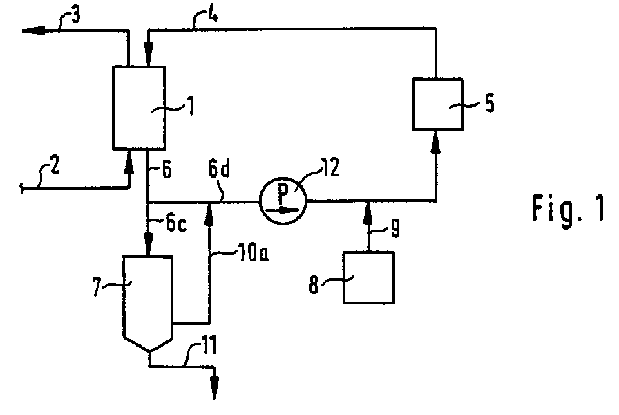
- Fig. 1 shows an apparatus for performing the method with an adsorber and a one-stage condensation system.
- Fig. 2 is an apparatus for performing the method with two adsorbers and a multi-stage condensation system.
- Fig. 1 shows an adsorber (1) with an input line (2) for gas, the Pollutants is loaded and an outlet line (3) for the cleaned gas.
- Adsorber (1) is connected to a heating device (5) via a line (4).
- a line (6) leads the desorbent from the adsorber (1).
- the Line (6) is branched into a line (6c) which is connected to a condensation system (7) is connected and a line (6d) in which the desorbent via Heater (5) in the adsorber (1) is returned.
- the desorbent is fed from a storage container (8) via line (9) to line (6d).
- the coming from the condensation system (7) and freed of pollutants Gas can either be discharged to the environment or via line (10) Raw gas stream in the line (2) are supplied.
- a blower (12) can also be arranged in the circuit.
- the blower (12) is here arranged in front of the heating device (5) in the line (6d). It is also possible arrange the fan (12) in the line (4) after the heating device (5).
- the adsorption system (1) often consists of at least two Adsorbers. It is also advantageous if the condensation system (7) has several stages is constructed. Such a device is shown in FIG. 2. Be here two adsorbers (1a, 1b) are used.
- the control of the Desorbent cycle or the raw gas and clean gas flow takes place via in Shut-off or control devices (19, 20, 21, 22, 23, 24, 25, 26).
- the condensation system is constructed as a multi-stage system. she consists of a precondensation (7a) with water as the cooling medium.
- the precondensation (7a) can also be shown with two condensation stages, for example one stage with cooling water and a second stage with well water, operate.
- a cryocondensation (7b) is provided as a further stage downstream of the precondensation (7a).
- the condensates can over one condensate drain (11a and 11b) each for recycling or disposal be fed.
- the gas coming from the cryocondensation (7b) can over a line (10b) is fed to the raw gas stream in line (2).
- the gas but can also according to the device shown in Fig. 1 Desorbent in the desorbent circuit are supplied or to the Environment are discharged, which is not shown here.
- the cryocondensation (7b) is operated with the desorbent from a cryogenic Desorbent supply (8) via line (13) is obtained. Furthermore, a Intermediate store (14) is provided for the desorbent, which has a line (15) is connected, whereby the coming from the cryocondensation stage (7b) mostly gaseous desorbent is supplied. From the clipboard (14) the desorbent via a line (16) the desorbent circuit are supplied, the control via a line (16) arranged shut-off or control device (27) takes place.
- a cooling device parallel to the heating device (5) (17) can be arranged via lines (18a, 18b) with the desorbent circuit connected is.
- the cooling device (17) using the in the lines (6d) and (18a) arranged shut-off or control devices (28, 29) are switched into the desorbent circuit.
- the desorbent of the desorbent circuit can, if necessary a certain temperature can be set.
- the device of FIG. 2 can also with discontinuously occurring exhaust air flow be carried out with a single-stranded adsorber (only 1a).
- a requirement for this is that when leaving the cryocondensation plant (7b) the loading of the desorption gas corresponds to the required emission limit values if this is released into the environment.
- the nitrogen as a desorbent can always be taken from a cryogenic desorbent supply (8) or As a nitrogen source, a pressure swing adsorption system in connection with a cold gas mixer can be used.
- a pressure swing adsorption system in connection with a cold gas mixer can be used.
- the process according to the invention can contain excess, gaseous desorbent, for example nitrogen. This can be used for other purposes. So can Nitrogen, for example, is used for inerting purposes of other processes will.
Landscapes
- Chemical & Material Sciences (AREA)
- Engineering & Computer Science (AREA)
- Analytical Chemistry (AREA)
- General Chemical & Material Sciences (AREA)
- Oil, Petroleum & Natural Gas (AREA)
- Chemical Kinetics & Catalysis (AREA)
- Separation Of Gases By Adsorption (AREA)
Abstract
Bei einem Verfahren zur Desorption von ein oder mehreren Adsorbern (1) mit einem im
Kreislauf geführten gasförmigen Desorptionsmittel wird a) gasförmiges
Desorptionsmittel erhitzt und dem Adsorber (1) zugeführt und so der Adsorber
aufgeheizt, b) danach das mit Schadstoffen beladene Desorptionsmittel aus dem
Adsorber abgeführt und in zwei Teilströme aufgeteilt, c) der erste Teilstrom des mit
Schadstoffen beladenen Desorptionsmittels aus dem Adsorber gemäß der
Verfahrensstufe a) wieder erhitzt und dem Adsorber wieder zugeführt, d) der zweite
Teilstrom des mit Schadstoffen beladenen Desorptionsmittels aus dem Adsorber aus
dem Desorptionsmittel- Kreislauf abgeführt und e) zum Ende der Desorptionszeit des
Adsorbers gasförmiges Desorptionsmittel dem Desorptionsmittel-Kreislauf zugeführt
und/oder das Abführen des zweiten Teilstroms des mit Schadstoffen beladenen
Desorptionsmittels aus dem Desorptionsmittel-Kreislauf gemäß der Verfahrensstufe
d) unter Anlegen eines Vakuums durchgeführt.
Description
Die Erfindung betrifft ein Verfahren zur Desorption von einem oder mehreren Adsorbern nach dem Oberbegriff des Anspruchs 1 sowie eine für die Durchführung des Verfahrens geeignete Vorrichtung.The invention relates to a process for the desorption of one or more Adsorbers according to the preamble of claim 1 and one for the implementation device suitable for the method.
Abgase, die mit Schadstoffen beladen sind, werden zur Reinigung Adsorbern zugeführt, in denen ihnen die Schadstoffe entzogen werden. Sind die Adsorptionskapazitäten des Adsorptionsmittels ausgeschöpft, so muß es durch Desorption regeneriert werden. Dies geschieht, indem es mit einem Strom eines Desorptionsgases beaufschlagt wird. Als Desorptionsgase finden sowohl Wasserdampf als auch heißes Stickstoffgas Verwendung. Bei der Verwendung von Stickstoff werden nach der Desorption die Desorptionsgase durch Kondensation und/oder Ausfrieren von ihrer Schadstoffbeladung befreit. Das Desorptionsgas wird dabei im Kreislauf geführt. Nachteilig bei diesen Verfahren nach dem Stand der Technik ist es, daß das Desorptionsgas zuerst aufgeheizt wird, damit die Schadstoffe überhaupt aus dem Adsorber ausgetragen werden können und nach Verlassen des Adsorbers abgekühlt wird, um die Schadstoffe zu kondensieren bzw. auszufrieren.Exhaust gases loaded with pollutants become adsorbers for cleaning supplied in which the pollutants are removed. Are the Adsorption capacity of the adsorbent exhausted, so it must Desorption can be regenerated. This is done by using a stream of one Desorption gas is applied. As desorption gases find both Steam as well as hot nitrogen gas use. When using After desorption, nitrogen becomes the desorption gases through condensation and / or freezing free of their pollutant load. The desorption gas will thereby in a cycle. A disadvantage of these methods according to the prior art The technique is that the desorption gas is first heated so that the Pollutants can be discharged from the adsorber at all and after Leaving the adsorber is cooled to condense the pollutants or freeze out.
Der Erfindung liegt die Aufgabe zugrunde, ein Verfahren und eine Vorrichtung zu schaffen, mit denen die Regeneration eines schadstoffbeladenen Adsorbers mit einem relativ geringen Energieaufwand möglich ist.The invention has for its object to a method and an apparatus create with which the regeneration of a pollutant-laden adsorber a relatively small amount of energy is possible.
Ausgehend von dem im Oberbegriff des Anspruchs 1 berücksichtigten Stand der Technik ist die Aufgabe erfindungsgemäß durch ein Verfahren gelöst, welches dadurch gekennzeichnet ist, daß a) gasförmiges Desorptionsmittel erhitzt und dem Adsorber zugeführt wird, wodurch der Adsorber aufgeheizt wird, b) danach das mit Schadstoffen beladene Desorptionsmittel aus dem Adsorber abgeführt wird und in zwei Teilströme aufgeteilt wird, c) der erste Teilstrom des mit Schadstoffen beladenen Desorptionsmittels aus dem Adsorber gemäß der Verfahrensstufe a) wieder erhitzt und dem Adsorber wieder zugeführt wird, d) der zweite Teilstrom des mit Schadstoffen beladenen Desorptionsmittels aus dem Adsorber aus dem Desorptionsmittel-Kreislauf abgeführt wird und e) zum Ende der Desorptionszeit des Adsorbers gasförmiges Desorptionsmittel dem Desorptionsmittel-Kreislauf zugeführt wird und/oder das Abführen des zweiten Teilstroms des mit Schadstoffen beladenen Desorptionsmittels aus dem Desorptionsmittel-Kreislauf gemäß der Verfahrensstufe d) unter Anlegen eines Vakuums erfolgt.Based on the state of the art considered in the preamble of claim 1 Technology, the object is achieved according to the invention by a method which is characterized in that a) gaseous desorbent is heated and the Adsorber is supplied, whereby the adsorber is heated, b) thereafter with Desorbent laden pollutants is removed from the adsorber and in two sub-streams is divided, c) the first sub-stream of pollutants loaded desorbent from the adsorber according to process step a) heated again and the adsorber is fed again, d) the second partial stream of desorbent loaded with pollutants from the adsorber from the Desorbent circuit is discharged and e) at the end of the desorption time Adsorber's gaseous desorbent is fed to the desorbent circuit and / or the removal of the second partial stream of the one loaded with pollutants Desorbent from the desorbent cycle according to the process step d) is carried out with a vacuum.
Während der Desorption des Adsorbers entstehen hoch schadstoffhaltige Dämpfe. Der Anteil an Dampf im Desorptionsmittel-Kreislauf wird während des Aufheizens und der steigenden Desorption des Adsorbers größer und kann soweit ansteigen, daß das Desorptionsmittel im Desorptionsmittel-Kreislauf hoch schadstoffhaltig ist und zum überwiegenden Teil aus Dampf besteht. Der im Desorptionsmittel-Kreislauf geführte erste Teilstrom, welcher noch eine relativ hohe Temperatur aufweist, kann dann mit einem relativ geringen Energieaufwand auf die zur weiteren Aufheizung des Adsorbers oder die zur Aufrechterhaltung der Temperatur bzw. Desorption des Adsorbers benötigte Temperatur erhitzt werden. Gegenüber den Verfahren nach dem Stand der Technik, bei denen der gesamte Volumenstrom zunächst abgekühlt werden muß, um die Schadstoffe auszukondensieren und danach wieder erhitzt wird, ist eine Energieeinsparung möglich. Daher kann die Desorption des Adsorbers gemäß der Erfindung auf vergleichsweise wirtschaftliche Weise erfolgen. Zum Ende der Desorption wird dem Desorptionsmittel-Kreislauf gasförmiges Desorptionsmittel zugeführt und das System gespült, damit der Adsorber anschließend wieder mit Rohgas beaufschlagt werden kann. Anstatt des Spülens mit Desorptionsmittel ist es ebenso möglich, an den zweiten Teilstrom des mit Schadstoffen beladenen Desorptionsmittels aus dem Desorptionsmittel-Kreislauf gemäß der Verfahrensstufe d) ein Vakuums anzulegen und so die restlichen Schadstoffe aus dem Adsorber zu entfernen.Vapors containing high levels of pollutants are formed during the desorption of the adsorber. The proportion of steam in the desorbent circuit is increased during heating and the increasing desorption of the adsorber is larger and can rise as far that the desorbent in the desorbent cycle contains high levels of pollutants and consists mostly of steam. The one in the desorbent cycle guided first partial stream, which still has a relatively high temperature then with a relatively small amount of energy for further heating of the adsorber or to maintain the temperature or desorption of the Adsorbers temperature needed to be heated. Compared to the procedure the prior art, in which the entire volume flow is initially cooled must be condensed to condense and then heated again energy saving is possible. Therefore, the desorption of the adsorber according to the invention in a comparatively economical manner. To the end the desorption becomes the desorbent cycle gaseous desorbent fed and the system rinsed so that the adsorber then again with Raw gas can be applied. Instead of rinsing with desorbent it is also possible, to the second partial flow of the contaminated Desorbent from the desorbent cycle according to the process step d) create a vacuum and so the remaining pollutants from the adsorber remove.
Als Desorptionsmittel werden vorzugsweise nicht brennbare, tiefkalte verflüssigte Gase, wie beispielsweise Stickstoff, Argon oder Helium, eingesetzt. Es können jedoch auch andere Desorptionsmittel, verwendet werden, welche die thermodynamischen Voraussetzungen erfüllen. Gemäß einer bevorzugten Ausführungsform der Erfindung wird Stickstoff als Desorptionsmittel eingesetzt.Non-flammable, cryogenic liquefied materials are preferably used as desorbents Gases such as nitrogen, argon or helium are used. It can however, other desorbents can also be used which the meet thermodynamic requirements. According to a preferred Embodiment of the invention, nitrogen is used as a desorbent.
Der während der Desorption der Adsorber entstehende Dampf wird vorteilhaft in einer ein- oder mehrstufigen Kondensationsanlage niedergeschlagen. Unter dem Begriff "Kondensationsanlage" im Sinne der Erfindung ist jede beliebige Vorrichtung zu verstehen, die es ermöglicht, unter Nutzung des Kälteinhaltes eines Kondensationsmittels eine Trennung der Schadstoffe aus dem Desorptionsmittel herbeizuführen. Es ist vorteilhaft, zur Kondensation das zur Desorption verwendete, noch nicht erhitzte Desorptionsmittel, zu verwenden. Daher ist es vorgesehen, eine mehrstufige Kondensationsanlage mit einer Vorkondensation und einer anschließenden Kryokondensation einzusetzen. Eine technisch ausreichende Vorkondensation kann beispielsweise durch Kühlung mit Wasser bzw. Brunnenwasser und/oder durch eine Kältemaschine bzw. vor Ort vorhandene Kühlsole erfolgen.The steam generated during the desorption of the adsorbers is advantageous in a single or multi-stage condensation system. Under the The term "condensation system" in the sense of the invention is any device to understand, which makes it possible to use a cold content Condensation agent separates the pollutants from the desorbent bring about. For condensation, it is advantageous to use the desorption not yet heated desorbent to use. It is therefore envisaged that multi-stage condensation system with one precondensation and one subsequent cryocondensation. A technically sufficient Precondensation can be achieved, for example, by cooling with water or Well water and / or by a chiller or existing on site Cooling brine take place.
Nach der Erfindung ist es vorgesehen, daß das die Kondensationsanlage verlassende gasförmige Desorptionsmittel dem Rohgasstrom zugeführt wird, der zur Adsorption in den Adsorber geleitet wird, der im Adsorptionsbetrieb arbeitet oder daß das die Kondensationsanlage verlassende gasförmige Desorptionsmittel dem Desorptionsmittel im Desorptionsmittel-Kreislauf zugeführt wird, welches zur Desorption in den Adsorber geleitet wird, der im Desorptionsbetrieb arbeitet. Durch diese Verfahrensführung werden im Desorptionsmittel eventuell vorhandene Schadstoffe nicht in die Umgebung ausgetragen. Ist die letzte Kondensationsstufe, beispielsweise eine Kryokondensationsstufe, so ausgelegt, daß die Schadstoffe aus dem Desorptionsgasstrom nahezu vollständig entfernt werden und deren Menge unterhalb der geforderten Grenzwerte bleibt, so kann das Desorptionsmittel aber auch in die Umgebung abgeleitet werden.According to the invention it is provided that the condensation plant leaving gaseous desorbent is fed to the raw gas stream, which for Adsorption is passed into the adsorber, which works in the adsorption mode or that the gaseous desorbent leaving the condensation plant Desorbent is supplied in the desorbent circuit, which for Desorption is passed into the adsorber, which works in the desorption mode. By this procedure may be present in the desorbent Pollutants are not discharged into the environment. Is the last condensation stage, For example, a cryocondensation stage, designed so that the pollutants from the desorption gas stream are almost completely removed and their amount remains below the required limits, but the desorbent can can also be derived into the environment.
Gemäß einer weiteren Ausführungsform der Erfindung wird ein in dem Adsorber entstehender Druck durch ein Ventil entspannt und Verluste an Desorptionsmittel werden durch Zuführung von Desorptionsmittel in den Kreislauf kompensiert.According to a further embodiment of the invention, an in the adsorber pressure released by a valve and loss of desorbent are compensated for by adding desorbent to the circuit.
Nach der Erfindung ist vorgesehen, daß das gasförmige Desorptionsmittel mindestens einem ersten Adsorber einer Adsorptionsanlage zugeführt wird, während einem zweiten Adsorber Rohgas zugeführt wird und daß anschließend nach erfolgter Desorption des ersten Adsorbers diesem Rohgas zugeführt wird, während dem zweiten Adsorber das gasförmige Desorptionsmittel zugeführt wird. Es ist aber ebenso möglich, daß das gasförmige Desorptionsmittel einem kontinuierlich arbeitenden Adsorber zugeführt wird. Bei nicht kontinuierlich anfallenden Abgasströmen ist es auch denkbar, daß nur ein Adsorber verwendet wird, der bei anstehendem schadsfoffbeladenen Abgas im Adsorptionsbetrieb arbeitet und in Zeiten, in denen kein schadstoffbeladenes Abgas ansteht, erfindungsgemäß desorbiert wird.According to the invention it is provided that the gaseous desorbent at least a first adsorber is supplied to an adsorption system, while a second adsorber raw gas is supplied and that after desorption of the first adsorber is supplied to this raw gas while the gaseous desorbent is fed to the second adsorber. But it is also possible that the gaseous desorbent is continuous working adsorber is supplied. In the case of non-continuously occurring Exhaust gas streams, it is also conceivable that only one adsorber is used, which at the existing pollutant-laden exhaust gas works in the adsorption mode and in Times in which no pollutant-laden exhaust gas is present, according to the invention is desorbed.
Nach der Erfindung kann der Adsorber durch den heißen Gasstrom des Desorptionsmittels, direktes Heizen und/oder Evakuieren desorbiert werden.According to the invention, the adsorber through the hot gas stream Desorbent, direct heating and / or evacuation can be desorbed.
Das erfindungsgemäße Verfahren wird vorteilhaft mit Hilfe einer Vorrichtung durchgeführt, die mit mindestens einem Adsorber, mindestens einer Eingangsleitung und mindestens einer Ausgangsleitung für das zu reinigende Gas, mindestens einer Eintrittsleitung und mindestens einer Austrittsleitung besteht, bei der in der Eintrittsleitung für das Desorptionsmittel eine Heizvorrichtung angeordnet ist und die dadurch gekennzeichnet ist, daß die aus dem Adsorber führende Austrittsleitung vor oder nach einer Vorrichtung zur Aufrechterhaltung eines Desorptionsmittel-Kreislaufs verzweigt ist. Die Desorptionsanlage besteht vorteilhaft aus einer Vorkondensationsanlage und einer Kryokondensationsanlage. Dann ist es vorteilhaft, daß das aus der Kryokondensation kommende, vorwiegend gasförmige Desorptionsmittel zuerst einem Zwischenspeicher zugeführt wird, wobei es aus dem Zwischenspeicher dem Desorptionsmittel-Kreislauf bei Bedarf zugeführt werden kann. In der Eintrittsleitung für das Desorptionsmittel kann zusätzlich zu der Heizvorrichtung auch eine Kühlvorrichtung angeordnet sein, um die Temperatur des Desorptionsmittels im Desorptionsmittel-Kreislauf genau einstellen zu können. Als Vorrichtung zur Aufrechterhaltung des Desorptionsmittel-Kreislaufs ist es erfindungsgemäß vorgesehen, ein Gebläse, einen Kompressor oder eine Pumpe zu verwenden. Nach der Erfindung kann der Adsorber bzw. die Adsorptionsanlage auch ein Ventil aufweisen, wodurch überschüssiges Desorptionsmittel ausströmen kann. Schließlich ist es von Vorteil, wenn in dem Desorptionsmittel-Kreislauf eine Reinigungsvorrichtung für das gasförmige Desorptionsmittel vorgesehen ist.The method according to the invention is advantageous with the aid of a device performed with at least one adsorber, at least one input line and at least one outlet line for the gas to be cleaned, at least one Inlet line and at least one outlet line exists in which in the Inlet line for the desorbent is arranged a heater and the characterized in that the outlet line leading from the adsorber is in front or after a device for maintaining a desorbent circuit is branched. The desorption plant advantageously consists of a Pre-condensation plant and a cryocondensation plant. Then it is advantageous that the coming from the cryocondensation, mainly gaseous Desorbent is first fed to an intermediate storage, it from the Buffer can be fed to the desorbent circuit if necessary can. In the inlet line for the desorbent can in addition to the A cooling device can also be arranged to control the temperature of the heating device To be able to precisely set the desorbent in the desorbent circuit. As It is a device for maintaining the desorbent circulation provided according to the invention, a blower, a compressor or a pump use. According to the invention, the adsorber or the adsorption system can also have a valve, whereby excess desorbent can flow out. Finally, it is advantageous if one in the desorbent circuit Cleaning device for the gaseous desorbent is provided.
Das erfindungsgemäße Verfahren und die erfindungsgemäße Vorrichtung wird nun anhand von einem Ausführungsbeispiel und von zwei Abbildungen (Fig. 1 und Fig. 2) beispielhaft näher erläutert.The method and the device according to the invention will now using an exemplary embodiment and two illustrations (FIGS. 1 and 2) exemplified in more detail.
Ein Adsorber, der mit einem Rohgasstrom von ca. 30000 m3/h mit einem Dampfanteil von ca. 6 g/ m3 für eine Zeitdauer von ca. 5 h beaufschlagt wurde, wird durch eine ebensolange Desorptionszeit unter Kreislaufführung von ca. 20000 m3/h Stickstoff als Desorptionsmittel regeneriert. Vor Einleitung in den Adsorber wird das Desorptionsmittel auf eine Temperatur von ca. 200 °C aufgeheizt. Nach Verlassen des Adsorbers beträgt die Temperatur des Desorptionsmittels noch ca. 20°C zu Anfang und 180 °C am Ende der Desorptionszeit. Auf die benötigte Temperatur wird nur das im Desorptionsmittel-Kreislauf befindliche Desorptionsmittel des ersten Teilstroms wieder erhitzt und dem Adsorber zugeführt. Das im Kreislauf geführte Desorptionsmittel besteht anfangs aus ca. größer 90 % gasförmiger Phase. Während der Aufheizung wird der Gehalt an hoch schadstoffhaltigem Dampf immer größer, bis der aus dem Kreislauf abgezogene zweite Teilstrom an Desorptionsmittel von ca. 200 kg/h fast vollständig aus einer Dampfphase besteht. Gegen Ende der Desorptionszeit ist das im Kreislauf geführte Desorptionsmittel zu ca. größer 90 % dampfförmig. Nach der Desorptionsphase wird der Anteil an Dampf wieder geringer. Mit dem erfindungsgemäßen Verfahren wird nur eine relativ geringe Energiemenge zum Aufheizen des Desorptionsmittels im Kreislauf benötigt, da der im Kreislauf geführte erste Teilstrom des Desorptionsmittels vor der Erhitzung nicht abgekühlt werden muß. Darüber hinaus können der zur Desorption verwendete Stickstoff oder andere, hochwertige und zur Desorption geeignete Gase besonders wirtschaftlich genutzt werden. Ein Auskondensieren bzw. Ausfrieren der Schadstoffe aus dem beladenen Desorptionsgas kann durch Einbeziehung der tiefen Kälte des flüssigen Gases besonders effektiv erfolgen.An adsorber that has been charged with a crude gas flow of approx. 30,000 m 3 / h with a steam fraction of approx. 6 g / m 3 for a period of approx. 5 h is characterized by an equally long desorption time with circulation of approx. 20,000 m 3 / h regenerated nitrogen as a desorbent. Before being introduced into the adsorber, the desorbent is heated to a temperature of approx. 200 ° C. After leaving the adsorber, the temperature of the desorbent is still approx. 20 ° C at the beginning and 180 ° C at the end of the desorption time. To the required temperature, only the desorbent in the first partial stream located in the desorbent circuit is reheated and fed to the adsorber. The circulating desorbent initially consists of approximately 90% gaseous phase. During the heating, the content of high pollutant vapor increases until the second partial stream of desorbent of approx. 200 kg / h withdrawn from the circuit consists almost entirely of a vapor phase. Towards the end of the desorption time, the circulating desorbent is approximately 90% vaporous. After the desorption phase, the proportion of steam decreases again. With the method according to the invention, only a relatively small amount of energy is required to heat the desorbent in the circuit, since the first partial stream of the desorbent, which is circulating, does not have to be cooled before the heating. In addition, the nitrogen used for desorption or other high quality gases suitable for desorption can be used particularly economically. Condensation or freezing out of the pollutants from the loaded desorption gas can take place particularly effectively by including the deep cold of the liquid gas.
Fig. 1 zeigt eine Vorrichtung zur Durchführung des Verfahrens mit einem Adsorber und einer einstufigen Kondensationsanlage.Fig. 1 shows an apparatus for performing the method with an adsorber and a one-stage condensation system.
In Fig. 2 ist eine Vorrichtung zur Durchführung des Verfahrens mit zwei Adsorbern und einer mehrstufigen Kondensationsanlage dargestellt.In Fig. 2 is an apparatus for performing the method with two adsorbers and a multi-stage condensation system.
Fig. 1 zeigt einen Adsorber (1) mit einer Eingangsleitung (2) für Gas, das mit Schadstoffen beladen ist und einer Ausgangsleitung (3) für das gereinigte Gas. Der Adsorber (1) ist über eine Leitung (4) mit einer Heizvorrichtung (5) verbunden. Über eine Leitung (6) wird das Desorptionsmittel aus dem Adsorber (1) geführt. Die Leitung (6) ist verzweigt in eine Leitung (6c), die mit einer Kondensationsanlage (7) verbunden ist und eine Leitung (6d), in der das Desorptionsmittel über die Heizvorrichtung (5) in den Adsorber (1) zurückgeführt wird. Das Desorptionsmittel wird aus einem Vorratsbehälter (8) über die Leitung (9) der Leitung (6d) zugeführt. Das aus der Kondensationsanlage (7) kommende und von Schadstoffen befreite Gas kann entweder an die Umgebung abgeführt werden oder über Leitung (10) dem Rohgasstrom in der Leitung (2) zugeführt werden. Das in der Kondensationsanlage (7) anfallende Kondensat wird über einen Kondensatablaß (11) einer Verwertung bzw. Entsorgung zugeführt. Zur Aufrechterhaltung des Desorptionsmittel-Kreislaufs kann ferner ein Gebläse (12) im Kreislauf angeordnet sein. Das Gebläse (12) ist hier vor der Heizvorrichtung (5) in der Leitung (6d) angeordnet. Es ist ebenso möglich, das Gebläse (12) in der Leitung (4) nach der Heizvorrichtung (5) anzuordnen. Fig. 1 shows an adsorber (1) with an input line (2) for gas, the Pollutants is loaded and an outlet line (3) for the cleaned gas. Of the Adsorber (1) is connected to a heating device (5) via a line (4). over a line (6) leads the desorbent from the adsorber (1). The Line (6) is branched into a line (6c) which is connected to a condensation system (7) is connected and a line (6d) in which the desorbent via Heater (5) in the adsorber (1) is returned. The desorbent is fed from a storage container (8) via line (9) to line (6d). The coming from the condensation system (7) and freed of pollutants Gas can either be discharged to the environment or via line (10) Raw gas stream in the line (2) are supplied. That in the condensation plant (7) accumulating condensate is via a condensate drain (11) recycling or disposal. To maintain the desorbent cycle a blower (12) can also be arranged in the circuit. The blower (12) is here arranged in front of the heating device (5) in the line (6d). It is also possible arrange the fan (12) in the line (4) after the heating device (5).
Bei dem erfindungsgemäßen Verfahren ist es vorteilhaft, mehrere Adsorber im Wechselbetrieb zu betreiben. Im Wechselbetrieb werden die Adsorber alternierend zur Reinigung des Rohgases eingesetzt und anschließend zur Regenerierung desorbiert. Daher besteht die Adsorptionsanlage (1) oft zumindest aus zwei Adsorbern. Zudem ist es von Vorteil, wenn die Kondensationsanlage (7) mehrstufig aufgebaut ist. Eine derartige Vorrichtung ist in der Fig. 2 dargestellt. Hier werden zwei Adsorber (1a, 1b) verwendet. Zum Betreiben im Wechselbetrieb sind bei den Adsorbern (1a, 1b) die Eingangsleitung für das Rohgas (2) in zwei Eingangsleitungen (2a, 2b), die Ausgangsleitung für das Reingas (3) in zwei Ausgangsleitungen (3a, 3b), die Zuleitung für das Desorptionsmittel (4) in zwei Zuleitungen (4a, 4b) und die Ausleitung des mit Schadstoffen beladenen Desorptionsmittels (6) in zwei Ausleitung (6a, 6b) aufgeteilt. Die Steuerung des Desorptionsmittel-Kreislaufs bzw. des Rohgas- und Reingasstroms erfolgt über in diesen Leitungen angeordnete Absperr- oder Regelvorrichtungen (19, 20, 21, 22, 23, 24, 25, 26). Die Kondensationsanlage ist als mehrstufige Anlage aufgebaut. Sie besteht aus einer Vorkondensation (7a) mit Wasser als Kühlmedium. Wie es hier dargestellt ist, kann die Vorkondensation (7a) auch mit zwei Kondensationsstufen, beispielsweise eine Stufe mit Kühlwasser und eine zweite Stufe mit Brunnenwasser, betrieben werden. Als weitere, der Vorkondensation (7a) nachgeschalteten Stufe ist eine Kryokondensation (7b) vorgesehen. Die anfallenden Kondensate können über jeweils einen Kondensatablaß (11a sowie 11b) einer Verwertung bzw. Entsorgung zugeführt werden. Das aus der Kryokondensation (7b) kommende Gas kann über eine Leitung (10b) dem Rohgasstrom in der Leitung (2) zugeführt werden. Das Gas kann aber auch entsprechend der in Fig. 1 gezeigten Vorrichtung dem Desorptionsmittel im Desorptionsmittel-Kreislauf zugeführt werden oder an die Umgebung abgeführt werden, was hier nicht dargestellt ist. Die Kryokondensation (7b) wird mit dem Desorptionsmittel betrieben, das aus einem tiefkalten Desorptionsmittel-Vorrat (8) über Leitung (13) bezogen wird. Ferner ist ein Zwischenspeicher (14) für das Desorptionsmittel vorgesehen, der mit einer Leitung (15) verbunden ist, wodurch das aus der Kryokondensationsstufe (7b) kommende, großteils gasförmige Desorptionsmittel zugeführt wird. Aus dem Zwischenspeicher (14) kann das Desorptionsmittel über eine Leitung (16) dem Desorptionsmittel-Kreislauf zugeführt werden, wobei die Steuerung über eine in der Leitung (16) angeordnete Absperr- oder Regelvorrichtung (27) erfolgt. Als weitere, mögliche Vorrichtungsvariante kann parallel zu der Heizvorrichtung (5) eine Kühlvorrichtung (17) angeordnet sein, die über Leitungen (18a, 18b) mit dem Desorptionsmittel-Kreislauf verbunden ist. Im Bedarfsfall kann die Kühlvorrichtung (17) mit Hilfe der in den Leitungen (6d) und (18a) angeordneten Absperr- oder Regelvorrichtungen (28, 29) in den Desorptionsmittel-Kreislauf geschaltet werden. Durch die Kühlvorrichtung (17) kann das Desorptionsmittel des Desorptionsmittel-Kreislaufs im Bedarfsfall auf eine bestimmte Temperatur eingestellt werden.In the method according to the invention, it is advantageous to use several adsorbers in the To operate alternately. In alternating operation, the adsorbers alternate used to clean the raw gas and then for regeneration desorbed. Therefore, the adsorption system (1) often consists of at least two Adsorbers. It is also advantageous if the condensation system (7) has several stages is constructed. Such a device is shown in FIG. 2. Be here two adsorbers (1a, 1b) are used. To operate in alternating operation with the Adsorbers (1a, 1b) the inlet line for the raw gas (2) in two Input lines (2a, 2b), the output line for the clean gas (3) in two Output lines (3a, 3b), the supply line for the desorbent (4) in two Supply lines (4a, 4b) and the discharge of those loaded with pollutants Desorbent (6) divided into two rejections (6a, 6b). The control of the Desorbent cycle or the raw gas and clean gas flow takes place via in Shut-off or control devices (19, 20, 21, 22, 23, 24, 25, 26). The condensation system is constructed as a multi-stage system. she consists of a precondensation (7a) with water as the cooling medium. Like it here the precondensation (7a) can also be shown with two condensation stages, for example one stage with cooling water and a second stage with well water, operate. As a further stage downstream of the precondensation (7a) a cryocondensation (7b) is provided. The condensates can over one condensate drain (11a and 11b) each for recycling or disposal be fed. The gas coming from the cryocondensation (7b) can over a line (10b) is fed to the raw gas stream in line (2). The gas but can also according to the device shown in Fig. 1 Desorbent in the desorbent circuit are supplied or to the Environment are discharged, which is not shown here. The cryocondensation (7b) is operated with the desorbent from a cryogenic Desorbent supply (8) via line (13) is obtained. Furthermore, a Intermediate store (14) is provided for the desorbent, which has a line (15) is connected, whereby the coming from the cryocondensation stage (7b) mostly gaseous desorbent is supplied. From the clipboard (14) the desorbent via a line (16) the desorbent circuit are supplied, the control via a line (16) arranged shut-off or control device (27) takes place. As another possible Device variant can be a cooling device parallel to the heating device (5) (17) can be arranged via lines (18a, 18b) with the desorbent circuit connected is. If necessary, the cooling device (17) using the in the lines (6d) and (18a) arranged shut-off or control devices (28, 29) are switched into the desorbent circuit. Through the cooler (17) the desorbent of the desorbent circuit can, if necessary a certain temperature can be set.
Die Vorrichtung der Fig. 2 kann bei diskontinuierlich anfallendem Abluftstrom auch mit einem einsträngigen Adsorber (nur 1a) ausgeführt sein. Eine Voraussetzung hierfür ist, daß beim Austritt aus der Kryokondensationsanlage (7b) die Beladung des Desorptionsgases den erforderlichen Emissionsgrenzwerten entspricht, wenn dieses an die Umgebung abgegeben wird. Der Stickstoff als Desorptionsmittel kann grundsätzlich einem tiefkalten Desorptionsmittel-Vorrat (8) entnommen werden oder als Stickstoffquelle kann eine Druck-Wechsel-Adsorptionsanlage in Verbindung mit einem Kaltgasmischer eingesetzt werden. Bei allen Varianten des erfindunsgemäßen Verfahrens kann überschüssiges, gasförmiges Desorptionsmittel, beispielsweise Stickstoff, anfallen. Dieses ist für andere Zwecke nutzbar. So kann Stickstoff beispielsweise für Inertisierungszwecke anderer Verfahren verwendet werden.The device of FIG. 2 can also with discontinuously occurring exhaust air flow be carried out with a single-stranded adsorber (only 1a). A requirement for this is that when leaving the cryocondensation plant (7b) the loading of the desorption gas corresponds to the required emission limit values if this is released into the environment. The nitrogen as a desorbent can always be taken from a cryogenic desorbent supply (8) or As a nitrogen source, a pressure swing adsorption system in connection with a cold gas mixer can be used. In all variants of the The process according to the invention can contain excess, gaseous desorbent, for example nitrogen. This can be used for other purposes. So can Nitrogen, for example, is used for inerting purposes of other processes will.
Claims (11)
durch die folgenden Verfahrenschritte gekennzeichnet,
characterized by the following process steps,
dadurch gekennzeichnet,
daß der zweite Teilstrom des mit Schadstoffen beladenen Desorptionsmittels aus der Verfahrensstufe d) einer ein- oder mehrstufigen Kondensationsanlage (7) zugeführt wird.Method according to claim 1,
characterized,
that the second partial flow of the desorbent loaded with pollutants from process stage d) is fed to a one- or multi-stage condensation system (7).
dadurch gekennzeichnet,
daß der zweite Teilstrom des mit Schadstoffen beladenen Desorptionsmittels aus der Verfahrensstufe d) einer mehrstufigen Kondensationsanlage zugeführt wird, die aus einer ein- oder mehrstufigen Vorkondensation (7a) und einer anschließenden Kryokondensation (7b) besteht.Method according to claim 2,
characterized,
that the second partial flow of the desorbent loaded with pollutants from process stage d) is fed to a multi-stage condensation system which consists of a single or multi-stage precondensation (7a) and a subsequent cryocondensation (7b).
dadurch gekennzeichnet,
daß das die Kondensationsanlage (7) verlassende gasförmige Desorptionsmittel dem Rohgasstrom zugeführt wird, der zur Adsorption in den Adsorber (1) geleitet wird, der im Adsorptionsbetrieb arbeitet oder daß das die Kondensationsanlage (7) verlassende gasförmige Desorptionsmittel dem Desorptionsmittel im Desorptionsmittel-Kreislauf zugeführt wird, welches zur Desorption in den Adsorber (1) geleitet wird, der im Desorptionsbetrieb arbeitet.Method according to claim 2 or 3,
characterized,
that the gaseous desorbent leaving the condensation system (7) is fed to the raw gas stream which is passed for adsorption into the adsorber (1) which works in the adsorption mode or that the gaseous desorbent leaving the condensation system (7) is fed to the desorbent in the desorbent circuit , which is passed for desorption in the adsorber (1), which works in the desorption mode.
dadurch gekennzeichnet,
daß ein in dem Adsorber (1) enstehender Druck durch ein Ventil entspannt wird und Verluste an Desorptionsmittel durch Zuführung von Desorptionsmittel in den Desorptionsmittel-Kreislauf kompensiert werden.Method according to one of claims 1 to 4,
characterized,
that a pressure arising in the adsorber (1) is released through a valve and losses of desorbent are compensated for by supplying desorbent to the desorbent circuit.
dadurch gekennzeichnet,
daß das gasförmige Desorptionsmittel mindestens einem ersten Adsorber (1a) einer Adsorptionsanlage zugeführt wird, während einem zweiten Adsorber (1b) Rohgas zugeführt wird und daß anschließend nach erfolgter Desorption des ersten Adsorbers (1a) diesem Rohgas zugeführt wird, während dem zweiten Adsorber (1b) das gasförmige Desorptionsmittel zugeführt wird.Method according to one of claims 1 to 5,
characterized,
that the gaseous desorbent is supplied to at least one first adsorber (1a) of an adsorption system, while raw gas is supplied to a second adsorber (1b) and that after the first adsorber (1a) has been desorbed, this raw gas is then supplied while the second adsorber (1b) the gaseous desorbent is supplied.
dadurch gekennzeichnet,
daß der Adsorber (1) durch den heißen Gasstrom des Desorptionsmittels und/oder direktes Heizen aufgeheizt wird. Method according to one of claims 1 to 6,
characterized,
that the adsorber (1) is heated by the hot gas stream of the desorbent and / or direct heating.
dadurch gekennzeichnet,
daß als Desorptionsmittel Stickstoff eingesetzt wird.Method according to one of claims 1 to 9,
characterized,
that nitrogen is used as the desorbent.
dadurch gekennzeichnet,
daß die aus dem Adsorber (1) führende Austrittsleitung (6) vor oder nach einer Vorrichtung zur Aufrechterhaltung eines Desorptionsmittelkreislaufs (12) verzweigt ist.Device with at least one adsorber (1), at least one inlet line (2) and at least one outlet line (3) for the gas to be cleaned, at least one inlet line (4) and at least one outlet line (6) for gaseous desorbent, in the inlet line (4) a heating device (5) or a heating device (5) and a cooling device (17) is arranged for the desorbent,
characterized,
that the outlet line (6) leading from the adsorber (1) is branched before or after a device for maintaining a desorbent circuit (12).
dadurch gekennzeichnet,
daß die Desorptionsanlage aus einer ein- oder mehrstufigen Vorkondensationsanlage (7a) und einer Kryokondensationsanlage (7b) besteht.Device according to claim 9,
characterized,
that the desorption system consists of a single or multi-stage precondensation system (7a) and a cryocondensation system (7b).
dadurch gekennzeichnet,
daß die Kryokondensationsanlage (7b) eine Stickstoff- Kryokondensationsanlage ist.Apparatus according to claim 10,
characterized,
that the cryocondensation plant (7b) is a nitrogen cryocondensation plant.
Applications Claiming Priority (2)
| Application Number | Priority Date | Filing Date | Title |
|---|---|---|---|
| DE1996135817 DE19635817A1 (en) | 1996-09-04 | 1996-09-04 | Method and device for desorbing adsorbers |
| DE19635817 | 1996-09-04 |
Publications (2)
| Publication Number | Publication Date |
|---|---|
| EP0827770A2 true EP0827770A2 (en) | 1998-03-11 |
| EP0827770A3 EP0827770A3 (en) | 1998-04-01 |
Family
ID=7804562
Family Applications (1)
| Application Number | Title | Priority Date | Filing Date |
|---|---|---|---|
| EP97114266A Withdrawn EP0827770A3 (en) | 1996-09-04 | 1997-08-19 | Method and apparatus for the desorption of adsorbers |
Country Status (2)
| Country | Link |
|---|---|
| EP (1) | EP0827770A3 (en) |
| DE (1) | DE19635817A1 (en) |
Cited By (1)
| Publication number | Priority date | Publication date | Assignee | Title |
|---|---|---|---|---|
| WO2020025214A1 (en) | 2018-07-28 | 2020-02-06 | Messer Group Gmbh | Method for recycling argon |
Families Citing this family (2)
| Publication number | Priority date | Publication date | Assignee | Title |
|---|---|---|---|---|
| DE102013017123A1 (en) * | 2013-10-15 | 2015-04-16 | Linde Aktiengesellschaft | Polymerization plant with regenerating device for adsorptive and / or catalytic purification device, regenerating device and regeneration method |
| CN114392632B (en) * | 2022-01-30 | 2022-11-11 | 浙江省生态环境科学设计研究院 | Nitrogen-protected organic waste gas condensation and recovery treatment method for degreasing process |
Family Cites Families (6)
| Publication number | Priority date | Publication date | Assignee | Title |
|---|---|---|---|---|
| GB1181989A (en) * | 1966-12-09 | 1970-02-18 | Continental Oil Co | Method and apparatus for processing Hydrocarbon Gas Streams |
| JPS56124423A (en) * | 1980-03-05 | 1981-09-30 | Mitsubishi Electric Corp | Water making apparatus |
| DE3042081A1 (en) * | 1980-11-07 | 1982-05-13 | Lohmann Gmbh & Co Kg, 5450 Neuwied | Reclaiming solvent from adsorbent - esp. solvent removed from waste air leaving painting plant, where energy is also reclaimed |
| US5187131A (en) * | 1990-01-16 | 1993-02-16 | Tigg Corporation | Method for regenerating particulate adsorbents |
| DE4224778A1 (en) * | 1992-07-27 | 1994-02-03 | Horst Dr Grochowski | Disposal procedures for environmental toxins |
| DE19503052A1 (en) * | 1995-02-01 | 1996-08-08 | Bresch Entsorgung Gmbh | Process for the condensation of adsorbable and desorbable gases and device for carrying out the process |
-
1996
- 1996-09-04 DE DE1996135817 patent/DE19635817A1/en not_active Ceased
-
1997
- 1997-08-19 EP EP97114266A patent/EP0827770A3/en not_active Withdrawn
Cited By (1)
| Publication number | Priority date | Publication date | Assignee | Title |
|---|---|---|---|---|
| WO2020025214A1 (en) | 2018-07-28 | 2020-02-06 | Messer Group Gmbh | Method for recycling argon |
Also Published As
| Publication number | Publication date |
|---|---|
| EP0827770A3 (en) | 1998-04-01 |
| DE19635817A1 (en) | 1998-03-05 |
Similar Documents
| Publication | Publication Date | Title |
|---|---|---|
| DE3412007C2 (en) | Process for cleaning workpieces using a liquid solvent | |
| DE69107115T2 (en) | Process and apparatus for the adsorption purification of air to be distilled. | |
| DE69522269T2 (en) | Recovery of substances from effluents | |
| EP0144956B1 (en) | Process and apparatus for regenerating a solvent | |
| DE2532099B2 (en) | Process for increasing the pure nitrogen yield in cryogenic air separation processes and the arrangement for practicing this process | |
| EP0350677A1 (en) | Apparatus for the continuous separation and recovery of a solvent from a solvent-laden exhaust gas | |
| EP1901017A1 (en) | Method and facility for drying objects | |
| DE4121697C2 (en) | Process for the recovery of solvents adsorbed in an adsorber | |
| DE60301399T2 (en) | METHOD AND SYSTEM FOR THE DESORPTION AND RECOVERY OF DESORBED COMPOUNDS | |
| EP2084722B1 (en) | Method for cooling superconducting magnets | |
| EP0827770A2 (en) | Method and apparatus for the desorption of adsorbers | |
| EP0049782A1 (en) | Process for the cyclical desorption of adsorbents cyclically charged with absorbates | |
| DE3048649C2 (en) | Process for the recovery of chlorinated and / or fluorinated hydrocarbons adsorbed on activated carbon | |
| DE3428220A1 (en) | METHOD FOR COOLING OR WARMING A GAS | |
| EP0130546A2 (en) | Method of recovering solvents after treatment of a textile material | |
| DE19527960C2 (en) | Method and device for desorbing adsorbers | |
| EP1887301A1 (en) | Process and apparatus for cryogenic condensation | |
| EP0437221A2 (en) | Process for emission free desorption | |
| DE10338418B4 (en) | Process and plant for exhaust gas purification | |
| DE3002649C2 (en) | ||
| DE3244304A1 (en) | METHOD FOR ADSORPTIVELY CLEANING RAW GASES | |
| DE936714C (en) | Process for cleaning gases, in particular those for synthesis and heating purposes | |
| EP2025382B1 (en) | Method and device for treating products with a gas flow | |
| DE3303422C2 (en) | Process for the regeneration and inertization of the adsorber units, the molecular sieve and other devices for the low-water recovery of solvents and a device for carrying out this process | |
| DE2924179A1 (en) | Contaminated air cleaning process - uses refrigeration circuit with expansion turbine to cool below dew point of pollutant |
Legal Events
| Date | Code | Title | Description |
|---|---|---|---|
| PUAI | Public reference made under article 153(3) epc to a published international application that has entered the european phase |
Free format text: ORIGINAL CODE: 0009012 |
|
| PUAL | Search report despatched |
Free format text: ORIGINAL CODE: 0009013 |
|
| AK | Designated contracting states |
Kind code of ref document: A2 Designated state(s): AT BE CH DE FR GB LI LU NL |
|
| AK | Designated contracting states |
Kind code of ref document: A3 Designated state(s): AT BE CH DE DK ES FI FR GB GR IE IT LI LU MC NL PT SE |
|
| 17P | Request for examination filed |
Effective date: 19981001 |
|
| AKX | Designation fees paid |
Free format text: AT BE CH DE FR GB LI LU NL |
|
| RBV | Designated contracting states (corrected) |
Designated state(s): AT BE CH DE FR GB LI LU NL |
|
| 17Q | First examination report despatched |
Effective date: 19991022 |
|
| STAA | Information on the status of an ep patent application or granted ep patent |
Free format text: STATUS: THE APPLICATION IS DEEMED TO BE WITHDRAWN |
|
| 18D | Application deemed to be withdrawn |
Effective date: 20011023 |