EP0437221A2 - Process for emission free desorption - Google Patents
Process for emission free desorption Download PDFInfo
- Publication number
- EP0437221A2 EP0437221A2 EP91100133A EP91100133A EP0437221A2 EP 0437221 A2 EP0437221 A2 EP 0437221A2 EP 91100133 A EP91100133 A EP 91100133A EP 91100133 A EP91100133 A EP 91100133A EP 0437221 A2 EP0437221 A2 EP 0437221A2
- Authority
- EP
- European Patent Office
- Prior art keywords
- adsorbent
- gas
- container
- desorption
- adsorption
- Prior art date
- Legal status (The legal status is an assumption and is not a legal conclusion. Google has not performed a legal analysis and makes no representation as to the accuracy of the status listed.)
- Withdrawn
Links
Images
Classifications
-
- B—PERFORMING OPERATIONS; TRANSPORTING
- B01—PHYSICAL OR CHEMICAL PROCESSES OR APPARATUS IN GENERAL
- B01D—SEPARATION
- B01D53/00—Separation of gases or vapours; Recovering vapours of volatile solvents from gases; Chemical or biological purification of waste gases, e.g. engine exhaust gases, smoke, fumes, flue gases, aerosols
- B01D53/02—Separation of gases or vapours; Recovering vapours of volatile solvents from gases; Chemical or biological purification of waste gases, e.g. engine exhaust gases, smoke, fumes, flue gases, aerosols by adsorption, e.g. preparative gas chromatography
- B01D53/04—Separation of gases or vapours; Recovering vapours of volatile solvents from gases; Chemical or biological purification of waste gases, e.g. engine exhaust gases, smoke, fumes, flue gases, aerosols by adsorption, e.g. preparative gas chromatography with stationary adsorbents
-
- B—PERFORMING OPERATIONS; TRANSPORTING
- B01—PHYSICAL OR CHEMICAL PROCESSES OR APPARATUS IN GENERAL
- B01J—CHEMICAL OR PHYSICAL PROCESSES, e.g. CATALYSIS OR COLLOID CHEMISTRY; THEIR RELEVANT APPARATUS
- B01J20/00—Solid sorbent compositions or filter aid compositions; Sorbents for chromatography; Processes for preparing, regenerating or reactivating thereof
- B01J20/30—Processes for preparing, regenerating, or reactivating
- B01J20/34—Regenerating or reactivating
- B01J20/3483—Regenerating or reactivating by thermal treatment not covered by groups B01J20/3441 - B01J20/3475, e.g. by heating or cooling
-
- B—PERFORMING OPERATIONS; TRANSPORTING
- B01—PHYSICAL OR CHEMICAL PROCESSES OR APPARATUS IN GENERAL
- B01J—CHEMICAL OR PHYSICAL PROCESSES, e.g. CATALYSIS OR COLLOID CHEMISTRY; THEIR RELEVANT APPARATUS
- B01J20/00—Solid sorbent compositions or filter aid compositions; Sorbents for chromatography; Processes for preparing, regenerating or reactivating thereof
- B01J20/30—Processes for preparing, regenerating, or reactivating
- B01J20/34—Regenerating or reactivating
- B01J20/3491—Regenerating or reactivating by pressure treatment
-
- B—PERFORMING OPERATIONS; TRANSPORTING
- B01—PHYSICAL OR CHEMICAL PROCESSES OR APPARATUS IN GENERAL
- B01D—SEPARATION
- B01D2257/00—Components to be removed
- B01D2257/70—Organic compounds not provided for in groups B01D2257/00 - B01D2257/602
- B01D2257/704—Solvents not covered by groups B01D2257/702 - B01D2257/7027
-
- B—PERFORMING OPERATIONS; TRANSPORTING
- B01—PHYSICAL OR CHEMICAL PROCESSES OR APPARATUS IN GENERAL
- B01D—SEPARATION
- B01D2259/00—Type of treatment
- B01D2259/40—Further details for adsorption processes and devices
- B01D2259/402—Further details for adsorption processes and devices using two beds
-
- B—PERFORMING OPERATIONS; TRANSPORTING
- B01—PHYSICAL OR CHEMICAL PROCESSES OR APPARATUS IN GENERAL
- B01D—SEPARATION
- B01D2259/00—Type of treatment
- B01D2259/40—Further details for adsorption processes and devices
- B01D2259/41—Further details for adsorption processes and devices using plural beds of the same adsorbent in series
-
- B—PERFORMING OPERATIONS; TRANSPORTING
- B01—PHYSICAL OR CHEMICAL PROCESSES OR APPARATUS IN GENERAL
- B01J—CHEMICAL OR PHYSICAL PROCESSES, e.g. CATALYSIS OR COLLOID CHEMISTRY; THEIR RELEVANT APPARATUS
- B01J2220/00—Aspects relating to sorbent materials
- B01J2220/50—Aspects relating to the use of sorbent or filter aid materials
- B01J2220/56—Use in the form of a bed
Definitions
- some adsorbents perform important functions by not only cleaning the exhaust air, but at the same time enabling the pollutants to be recovered in so-called recycling, since most of these pollutants are used as auxiliaries in the relevant processes.
- This recycling is with some other exhaust air purification processes, such as thermal or catalytic combustion, are not possible.
- vacuum purging gas desorption was chosen in order to avoid wastewater problems and corrosion in damp apparatus on the one hand, and also because with inert gas ( Nitrogen) can be switched more easily to loaded adsorption containers of different origins and with different loading substances.
- inert gas Nitrogen
- a closed gas circuit was chosen in the invention, in which the circulating gas has the function on the one hand of delivering the desorption heat to the adsorbent and on the other hand of transporting the desorbed steam - mostly solvent - to the cooling surfaces for condensation.
- the method according to the invention now proves to be surprisingly good, since on the cold pressure side of the gas circuit after cooling and condensation, the further purification of the circuit gas is brought about by adsorption on an already relatively highly loaded auxiliary adsorber. Due to the favorable temperature and pressure conditions prevailing for the adsorption at this point in the gas cycle, it is possible to achieve very high loads in this auxiliary adsorber, which on the other hand can be desorbed again at high temperature and under vacuum with significantly less energy expenditure and then condensed than would be possible with low temperature condensation.
- An exchange container H contains the adsorbent to be regenerated, through which hot circulating gas flows at low pressure (for example 0.1 bar).
- the circulating gas enriched with desorbate after flowing through the exchange container H is pressed by a blower G into a pressure part limited between the blower G and a throttle element D and then expanded via the throttle element D into the vacuum part delimited by the throttle element D and the blower G.
- the gas circuit goes via a heat recuperator R, which pre-cools the gas stream with heat recovery, via a cooler and condenser C, in which cooling is carried out to the dew point, into an auxiliary adsorber K, in which the circulating gas releases its residual load almost completely by adsorption.
- the cycle gas goes through the preheating heat recuperator R to a heater E, then the heated pure cycle gas relaxes in the low-pressure chamber, ie to the tank to be regenerated H.
- the z. B. was previously switched as auxiliary adsorber K.
- the loading of the cycle gas is further increased, whereby the subsequent condensation in the cooler and condenser C can take place at a moderately low temperature. The condensate can then be removed and "recycled".
- the circuit shown in FIG. 1 can be varied in different ways: Either, as explained above, the containers K and Z regularly change their functions, while the container H to be regenerated is always replaced by a new loaded replacement container. In this respect, the entire process is particularly suitable for a "central regeneration" in which exchangeable, transportable adsorbent containers repeatedly take the place of container H.
- the function changes in such a system can also be carried out in such a way that a freshly arriving loaded adsorbent container first takes over the function of the container K in order to then take over the function Z and only then the function H according to FIG. 1.
- the circuit according to FIG. 1 can also be used very cheaply for a large, stationary exhaust gas cleaning system with immovable adsorbent containers, particularly with a series connection of exhaust gas cleaning containers according to FIG. 2:
- two series-connected adsorption containers A1 and A2 are connected, which provide exhaust gas cleaning, while at the same time the adsorbent container H is regenerated in the closed gas circuit.
- the containers A1 and A2 regularly interchange the functions with H in such a way that two of these containers always function for exhaust gas purification, while the third is being regenerated.
- the containers A1 and H interchange their functions when the container H is completely regenerated and at the same time the container A1 is completely loaded with solvent.
- the change of function takes place in that container A2 - which at this time is about a quarter to half loaded - takes the place of container A1 and container H takes the place of A2, while A1 takes the regeneration position H.
Landscapes
- Chemical & Material Sciences (AREA)
- Analytical Chemistry (AREA)
- Chemical Kinetics & Catalysis (AREA)
- Organic Chemistry (AREA)
- Engineering & Computer Science (AREA)
- General Chemical & Material Sciences (AREA)
- Oil, Petroleum & Natural Gas (AREA)
- Physics & Mathematics (AREA)
- Thermal Sciences (AREA)
- Treating Waste Gases (AREA)
- Separation Of Gases By Adsorption (AREA)
Abstract
Description
In der Technik gibt es viele Prozesse, bei denen aus einem Gas mittels eines festen Adsorptionsmittels ein Stoff abgetrennt wird. Als Adsorptionsmittel, kurz Adsorbentien genannt, werden meist hochporöse körnige Stoffe eingesetzt wie Aktivkohle, Silikagel oder sogenannte Molekularsiebe.
Die aus dem Gas abzutrennende Substanz kann entweder ein Wertstoff als zu gewinnendes Produkt sein, oder aber ein sogenannter "Schadstoff", der nicht im Abgas in die Atmosphäre abgelassen werden darf wegen gesundheits-oder umweltschädigender Wirkung. Hierfür werden seit Jahrzehnten schärfer werdende Emissionsgrenzwerte festgelegt, um die immer deutlicher werdenden Umweltbelastungen zu verringern. Besonders in diesem Anwendungsgebiet erfüllen einige Adsorbentien wichtige Funktionen, indem sie nicht nur die Abluft reinigen, sondern gleichzeitig die Rückgewinnung der Schadstoffe im sogenannten Recycling ermöglichen, da die meisten dieser Schadstoffe als Hilfsstoffe in den betreffenden Prozessen gebraucht werden. Dieses Recycling ist bei einigen anderen Abluftreinigungsverfahren, wie beispielsweise thermischer oder katalytischer Verbrennung nicht möglich.There are many processes in technology in which a substance is separated from a gas by means of a solid adsorbent. Highly porous granular substances such as activated carbon, silica gel or so-called molecular sieves are mostly used as adsorbents, or adsorbents for short.
The substance to be separated from the gas can either be a valuable substance as the product to be obtained, or it can be a so-called "pollutant" that must not be released into the atmosphere in the exhaust gas because of its health or environmental effects. For this purpose, emission limit values have been tightened for decades in order to reduce the increasingly clear environmental pollution. In this area of application in particular, some adsorbents perform important functions by not only cleaning the exhaust air, but at the same time enabling the pollutants to be recovered in so-called recycling, since most of these pollutants are used as auxiliaries in the relevant processes. This recycling is with some other exhaust air purification processes, such as thermal or catalytic combustion, are not possible.
Nun ist aber auch bei der adsorptiven Abluftreinigung gerade dieser Rückgewinnungsprozeß für viele Substanzen noch nicht befriedigend gelöst. Zwar ist der eigentliche Adsorptionsprozeß, d.h. die Übertragung einer Substanz aus dem Gas auf ein frisches Adsorbens meistens verhältnismäßig einfach. Es braucht nur ein Adsorbens-Filter in den Gasstrom eingeschaltet zu werden, welches dann allerdings bei zunehmender Beladung mit der Substanz - im Folgenden der Klarheit halber immer als "Desorbat" bezeichnet, welches meist ein Lösungsmittels ist - in der Reinigungswirkung abnimmt. Schon lange vor Erreichen der möglichen Beladung muß ein solches einfaches Filter umgeschaltet werden, da im Austrittsgas durch sogenannten "Durchbruch" der zulässige Emissionsgrenzwert überschritten wird. Nach diesem einfachen Adsorptionsprozeß muß nun das beladene Adsorbens wieder regeneriert werden, um wieder eingesetzt werden zu können. In machen Fällen ist diese Regenerierung - nachfolgend im Gegensatz zur Adsorption als Desorption bezeichnet - technisch nicht möglich und wird durch eine Verbrennung des beladenen Adsorbens ersetzt. Dies hat natürlich negative wirtschaftliche und umweltbelastende Auswirkungen.
Daher ist man bemüht, die Desorptionstechnik zu verbessern, da die Desorption der Schritt ist, der viel Energie- sowie Apparate- und Bedienungsaufwand erfordert im Gegensatz zur vorherigen Adsorption. Allerdings ergibt sich aus der Literatur (1 bis 7 und etwa 150 Artikel aus Fachzeitschriften), daß außer theoretischen Betrachtungen zur Physik der Desorption sehr wenig technisch brauchbare Angaben über Desorptionsverfahren zu finden sind. Am häufigsten wird bisher die Wasserdampf-Desorption angewandt, die aber in vielen Fällen schwere Nachteile hat, nämlich:
Je nach Löslichkeit und Aufarbeitung des Desorbates entstehen schwere Abwasserprobleme, womit die Umweltbelastung aus der Luft ins Wasser verlagert wird. Auch entstehen in Anwesenheit von Wasser Korrosionsprobleme, die bei trockenen Verfahren nicht auftreten. Ferner muß nach der Dampfdesorption das feuchte Adsorbens vor dem erneuten Einsatz getrocknet werden, was Energie und zusätzliche Stillstandszeit erfordert.
Weiterer Energieverbrauch entsteht bei Wasserdampf-Desorption in der oft teuren Destillation der meist verdünnten wässrigen Desorbate. Über die "trockenen" Desorptionsverfahren sind in der Literatur nur andeutungsweise Angaben zu finden, indem entweder von "Temperatur-Wechsel" oder von "Druckwechsel" gesprochen wird ohne nähere Betrachtung der dabei entstehenden Umweltbelastungen. Denn für beide Verfahren wird einfach angenommen, daß bei der Desorption ein Gasstrom entweder bei höherer Temperatur oder bei tieferem Druck als bei der vorhergehenden Beladung des Adsorbens - d.h. bei der Adsorption - durch das Absorbens-Bett geleitet und anschließend mindestens teilweise als Abgas abgelassen wird.
Mit einem solchen Verfahren sind aber die durch die mit Recht in der letzten Zeit deutlich verschärften Abgasvorschriften z.B. der TA Luft entstandenen Abgasreinheiten nicht mehr zu erzielen. Daher wird oft der Ausweg gewählt, mindestens am Ende der Desorption mit soviel Gas durch das Adsorbens zu spülen, daß dabei zwar wegen der großen Gasmenge der Emissionsgrenzwert unterschritten, aber doch gleichzeitig eine mehr oder weniger große Schadstoffmenge in die Atmosphäre emittiert wird.Now, even in the case of adsorptive exhaust air purification, this recovery process for many substances has not yet been satisfactorily resolved. The actual adsorption process, ie the transfer of a substance from the gas to a fresh adsorbent, is usually relatively simple. It is only necessary to switch on an adsorbent filter in the gas stream, which, however, then decreases with increasing loading of the substance - hereinafter, for the sake of clarity, always referred to as "desorbate", which is usually a solvent - in terms of the cleaning action. Such a simple filter must be switched over long before the possible loading is reached, since the permissible emission limit value is exceeded in the outlet gas by so-called "breakthrough". After this simple adsorption process, the loaded adsorbent must now be regenerated in order to be able to be used again. In some cases this regeneration - hereinafter referred to as desorption in contrast to adsorption - is technically not possible and is replaced by combustion of the loaded adsorbent. Of course, this has negative economic and environmental impacts.
Therefore, efforts are being made to improve the desorption technique, since desorption is the step that requires a lot of energy, apparatus and operation, in contrast to the previous adsorption. However, it is evident from the literature (1 to 7 and about 150 articles from specialist journals) that, apart from theoretical considerations on the physics of desorption, very little information about desorption processes that is technically usable is very useful can be found. So far, water vapor desorption has been used most frequently, but in many cases it has serious disadvantages, namely:
Depending on the solubility and processing of desorbate, serious wastewater problems arise, which shift the environmental impact from the air to the water. In the presence of water, corrosion problems also arise which do not occur with dry processes. Furthermore, after the steam desorption, the moist adsorbent must be dried before being used again, which requires energy and additional downtime.
Further energy consumption occurs with water vapor desorption in the often expensive distillation of the mostly dilute aqueous desorbates. Information about the "dry" desorption processes can only be found in the literature by either talking about "temperature changes" or "pressure changes" without taking a closer look at the environmental pollution involved. Because for both processes it is simply assumed that a gas stream is passed through the absorbent bed either at a higher temperature or at a lower pressure than during the previous loading of the adsorbent - ie during adsorption - and then at least partially discharged as exhaust gas.
With such a method, however, the exhaust gas purities, which have rightly been significantly tightened in recent times, such as TA Luft, can no longer be achieved. Therefore, the way out is often chosen, at least at the end of the desorption with so much gas to be flushed through the adsorbent that the emission limit was not reached because of the large amount of gas, but at the same time a more or less large amount of pollutants is emitted into the atmosphere.
Durch eine solche Verfahrensweise wird mindestens ein Teil der vorherigen Bemühungen zur Abluftreinigung wieder illusorisch gemacht. So heißt es z. B. in dem modernen Standardwerk von Ruthven (5) betr. einer solchen Anwendung von Spülgas, daß ..." ferner das Desorbat normal nur in sehr kleinen Konzentrationen im Spülgas enthalten ist, so daß diese Methode normalerweise nicht angewandt würde, wenn das Desorbat zurückgewonnen werden soll".
Druck-Wechsel- oder Temperatur-Wechsel-Desorption wird in dem neuesten Werk von Kast (5) auf nur 2 bis 3 Seiten beschrieben. Auch hier ist allen beschriebenen Verfahren gemeinsam, daß ein mit Schadstoff beladener Abgasstrom in Kauf genommen wird.
In anderen Anwendungsfällen wird auf die Regeneration überhaupt verzichtet. So heißt es in dem ACHEMA-Bericht "Luftreinhaltung" (8) betreffend die Anwendung von leicht austauschbaren direkt in die Abluftleitung angeschlossene Aktivkohle-Fässer wörtlich: "Regeneration ist nicht vorgesehen. Die Kohle kann jedoch ausgeschüttet und durch frische ersetzt werden. Die verbrauchte Kohle kann verbrannt deponiert oder evtl. in einer Zentralanlage desorbiert werden".Such a procedure makes at least part of the previous efforts for exhaust air purification illusory again. So it says. B. in the modern standard work by Ruthven (5) regarding such an application of purge gas that ... "Furthermore, the desorbate is normally only contained in very small concentrations in the purge gas, so that this method would normally not be used if the desorbate should be recovered ".
Pressure-change or temperature-change desorption is described in the latest work by Kast (5) on only 2 to 3 pages. Here, too, all the methods described have in common that an exhaust gas stream laden with pollutant is accepted.
In other applications, regeneration is not used at all. According to the ACHEMA report "Air pollution control" (8) regarding the use of easily exchangeable activated carbon barrels directly connected to the exhaust pipe: "Regeneration is not planned. The coal can be poured out and replaced with fresh one. The used coal can be landfilled or possibly desorbed in a central facility ".
Nach welchen Verfahren und wie eine solche Zentralanlage arbeiten soll, wird allerdings nicht einmal angedeutet.Which method and how such a central system should work, however, is not even hinted at.
Das nachfolgend beschriebene neue Desorptionsverfahren wurde aber gerade mit dem Ziel einer zentralen Desorptionsanlage entwickelt, in welcher solche austauschbare Adsorbens-Behälter regeneriert werden sollen.The new desorption process described below was developed with the aim of a central desorption system in which such exchangeable adsorbent containers are to be regenerated.
Bei der Frage, ob der für die Desorption erforderliche Energie-Eintrag mittels Wasserdampf oder mit heißem Inertgas durchgeführt werden sollte, wurde die "Vakuumspülgasdesorption" gewählt, um dadurch einerseits Abwasserprobleme und Korrosion in feuchten Apparaten zu vermeiden, und andererseits auch, weil mit Inertgas (Stickstoff) leichter auf beladene Adsorptionsbehälter unterschiedlicher Herkunft und mit unterschiedlichen Beladungsstoffen umgeschaltet werden kann. Dabei war aus der Literatur keine Information über mögliche Verfahren des angestrebten emissionsfreien Desorbierens zu erhalten. Es wurde bei der Erfindung ein geschlossenen Gaskreislauf gewählt, in welchem das Kreislaufgas einerseits die Funktion hat, die Desorptionswärme an das Adsorbens zu liefern und andererseits den desorbierten Dampf - meistens Lösungsmittel - an die Kühlflächen zwecks Kondensation zu transportieren. Dabei ergab sich ein überraschend starker Effekt von Unterdruck auf der heißen Desorptionsseite, der dadurch erhöht werden konnte, daß der Unterdruck (Vakuum) nicht durch Ausschleusen von Gas aus der Anlage sondern durch Verlagern aus dem Desorptionsteil in den Kondensationsteil der Anlage erzeugt wurde. Dabei wird gleichzeitig mit dem Unterdruck im Desorptionsbehälter ein Überdruck im Kondensator erzeugt. Befinden sich etwa annähernd gleiche Volumen im Desorptionsteil und im Kondensationsteil, also je 50 % der Gesamtgasfüllung bei Normaldruck in der ganzen Anlage, so ergibt beispielsweise ein Druck von 0,1 bar absolut im Desorptionsteil folgende Verhältnisse:
In diesem Teil befinden sich noch 5 % der ursprünglichen Gesamt-Gasfüllung und 95 % im Kondensationsteil.When asked whether the energy input required for desorption should be carried out by means of steam or hot inert gas, "vacuum purging gas desorption" was chosen in order to avoid wastewater problems and corrosion in damp apparatus on the one hand, and also because with inert gas ( Nitrogen) can be switched more easily to loaded adsorption containers of different origins and with different loading substances. There was no information from the literature about possible methods of the desired emission-free desorbing. A closed gas circuit was chosen in the invention, in which the circulating gas has the function on the one hand of delivering the desorption heat to the adsorbent and on the other hand of transporting the desorbed steam - mostly solvent - to the cooling surfaces for condensation. This resulted in a surprisingly strong effect of negative pressure on the hot desorption side, which could be increased in that the negative pressure (vacuum) was not generated by discharging gas from the system but by moving it from the desorption part into the condensation part of the system. An overpressure is generated in the condenser simultaneously with the negative pressure in the desorption container. If there is approximately the same volume in the desorption section and in the condensation section, i.e. 50% of the total gas filling at normal pressure in the entire system, a pressure of 0.1 bar absolute in the desorption section results in the following conditions:
This part still contains 5% of the original total gas filling and 95% in the condensation part.
Dies bedeutet, daß im Gaskreislauf der Lösungsmittelteildruck von der Desorption bis zur Kondensation um den Faktor 95 : 5 = 19 erhöht und damit die Kondensation ermöglicht wird, ohne besonders tiefe Kühltemperatur zu erfordern.
Für Dämpfe mit nicht zu tiefer Siede- bzw. Kondensations-Temperatur kann mit diesem Kreislaufverfahren ein ausreichend reines Gas durch Kondensation erreicht werden, welches in der Lage ist, das beladene Adsorptionsmittel soweit zu regenerieren, daß dasselbe danach wieder für eine gute Abgas-Reinigung eingesetzt werden kann. Dabei ist die Anwendung von Kälteanlagen bis zu Kondensationstemperaturen von etwa -20 bis ca. -50 Grad C noch wirtschaftlich, wird aber bei noch tieferen Temperaturen zu kostspielig.
Hier erweist sich nun das erfindungsgemäße Verfahren als überraschend gut, da auf der kalten Druckseite des Gaskreislaufes nach der Kühlung und Kondensation die weitergehende Reinigung des Kreislaufgases durch Adsorption an einem schon relativ hochbeladenem Hilfsadsorber bewirkt wird. Aufgrund der an dieser Stelle des Gaskreislaufes herrschenden für die Adsorption günstigen Temperatur- und Druckverhältnisse ist es möglich, in diesem Hilfsadsorber sehr hohe Beladungen zu erzielen, die andererseits wieder bei hoher Temperatur und unter Vakuum mit bedeutend kleinerem Energieaufwand desorbiert und danach kondensiert werden können, als mit Tieftemperatur-Kondensation möglich wäre.This means that the partial solvent pressure in the gas circuit is increased by a factor of 95: 5 = 19 from desorption to condensation, thus enabling condensation without requiring a particularly low cooling temperature.
For vapors with a boiling or condensation temperature that is not too low, this cycle method can be used to achieve a sufficiently pure gas by condensation, which is able to regenerate the loaded adsorbent to such an extent that the same is then used again for good exhaust gas purification can be. The use of refrigeration systems down to condensation temperatures of around -20 to around -50 degrees C is still economical, but becomes too expensive at even lower temperatures.
Here, the method according to the invention now proves to be surprisingly good, since on the cold pressure side of the gas circuit after cooling and condensation, the further purification of the circuit gas is brought about by adsorption on an already relatively highly loaded auxiliary adsorber. Due to the favorable temperature and pressure conditions prevailing for the adsorption at this point in the gas cycle, it is possible to achieve very high loads in this auxiliary adsorber, which on the other hand can be desorbed again at high temperature and under vacuum with significantly less energy expenditure and then condensed than would be possible with low temperature condensation.
So war es erfindungsgemäß möglich, einen schon für die Abgasreinigung benutzten und daher mit Lösungsmittel beladenen Adsorptionsbehälter als Hilfsadsorber für die Gasreinigung bei der Regenerierung von vier weiteren beladenen Adsorptionsmittelbehältern einzusetzen. Dabei wird das aus diesen vier Behältern ausgetriebene Lösungsmittel überwiegend auf dem einen kalten Hilfsadsorber adsorbiert, wodurch dessen Beladung auf etwa das Dreifache des Anfangswertes gesteigert werden kann.
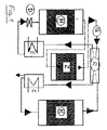
Wenn dieser derart hoch beladene Hilfsadsorber dann auf der heißen Vakuumseite in den Gaskreislauf eingeschaltet wird, ergeben sich so hohe Lösungsmittelgehalte im Gas, daß das Auskondensieren und damit das Recycling bei mäßig tiefen Temperaturen total möglich ist. Diese Wechselschaltung ist in Fig. 1 dargestellt: Die Pfeile in Fig. 1 bedeuten Strömungsrichtungen.
Ein Austauschbehälter H enthält das zu regenerierende Adsorptionsmittel, welches mit heißem Kreislaufgas bei niedrigem Druck (z.B. 0,1 bar) durchströmt wird. Das nach Durchströmen des Austauschbehälters H mit Desorbat angereicherte Kreislaufgas wird von einem Gebläse G in ein zwischen dem Gebläse G und einem Drosselorgan D begrenztes Druckteil gedrückt und dann über das Drosselorgan D in den von dem Drosselorgan D und dem Gebläse G begrenzten Unterdruckteil entspannt. Der Gaskreislauf geht über einen Wärme-Rekuperator R, der unter Wärmerückgewinnung den Gasstrom vorkühlt, über einen Kühler und Kondensator C, in welchem bis zum Taupunkt gekühlt wird, in einen Hilfsadsorber K, in dem das Kreislaufgas durch Adsorbieren seine Restbeladung fast völlig abgibt. Anschließend geht das Kreislaufgas über den eine Vorwärmung bewirkenden Wärme-Rekuperator R zu einem Erhitzer E, danach entspannt sich das erhitzte reine Kreislaufgas in dem Niederdruckraum, d.h. zum zu regenerierenden Behälter H. Diesem nachgeschaltet ist ein Zwischenbehälter Z, der z. B. vorher als Hilfsadsorber K geschaltet war. In dem anfangs hochbeladenem Zwischenbehälter Z wird die Beladung des Kreislaufgases weiter erhöht, wodurch die anschließende Kondensation im Kühler und Kondensator C mit mäßig tiefer Temperatur erfolgen kann. Das Kondensat kann dann abgenommen und "recyclt" werden.Thus, it was possible according to the invention to use an adsorption container already used for the exhaust gas purification and therefore loaded with solvent as an auxiliary adsorber for gas purification when regenerating four further loaded adsorbent containers. Here the solvent expelled from these four containers is predominantly adsorbed on the one cold auxiliary adsorber, whereby its loading can be increased to approximately three times the initial value.
If this auxiliary adsorber, which is so highly loaded, is then switched into the gas circuit on the hot vacuum side, the solvent contents in the gas are so high that condensation and thus recycling at moderately low temperatures is totally possible. This changeover circuit is shown in FIG. 1: The arrows in FIG. 1 mean flow directions.
An exchange container H contains the adsorbent to be regenerated, through which hot circulating gas flows at low pressure (for example 0.1 bar). The circulating gas enriched with desorbate after flowing through the exchange container H is pressed by a blower G into a pressure part limited between the blower G and a throttle element D and then expanded via the throttle element D into the vacuum part delimited by the throttle element D and the blower G. The gas circuit goes via a heat recuperator R, which pre-cools the gas stream with heat recovery, via a cooler and condenser C, in which cooling is carried out to the dew point, into an auxiliary adsorber K, in which the circulating gas releases its residual load almost completely by adsorption. Subsequently, the cycle gas goes through the preheating heat recuperator R to a heater E, then the heated pure cycle gas relaxes in the low-pressure chamber, ie to the tank to be regenerated H. This is followed by an intermediate tank Z, the z. B. was previously switched as auxiliary adsorber K. In the initially highly loaded intermediate container Z, the loading of the cycle gas is further increased, whereby the subsequent condensation in the cooler and condenser C can take place at a moderately low temperature. The condensate can then be removed and "recycled".
Die in Fig. 1 dargestellte Schaltung kann auf verschiedene Weise variiert werden:
Entweder tauschen, wie oben erläutert, die Behälter K und Z regelmäßig ihre Funktionen, während an die Stelle des zu regenerierenden Behälters H immer wieder ein neuer beladener Austauschbehälter tritt. Insofern ist das gesamte Verfahren besonders geeignet für eine "zentrale Regenerierung", in der austauschbare, transportable Adsorptionsmittelbehälter immer wieder an die Stelle des Behälters H treten.The circuit shown in FIG. 1 can be varied in different ways:
Either, as explained above, the containers K and Z regularly change their functions, while the container H to be regenerated is always replaced by a new loaded replacement container. In this respect, the entire process is particularly suitable for a "central regeneration" in which exchangeable, transportable adsorbent containers repeatedly take the place of container H.
Die Funktionswechsel in einer solchen Anlage können aber auch derart durchgeführt werden, daß ein frisch eintreffender beladener Adsorptionsmittelbehälter zu allererst die Funktion des Behälters K übernimmt, um danach die Funktion Z und dann erst die Funktion H gemäß Fig. 1 zu übernehmen.
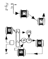
Andererseits kann die Schaltung gemäß Fig. 1 aber auch sehr günstig für eine große stationäre Abgas-Reinigungsanlage mit unbeweglichen Adsorptionsmittelbehältern angewandt werden, besonders mit Serien-Schaltung von Abgasreinigungsbehältern gemäß Fig. 2:
Dabei sind parallel zu der in Fig. 1 dargestellten 3-stufigen Desorptionsanlage zwei in Serie geschaltete Adsorptionsbehälter A1 und A2 geschaltet, welche die Abgas-Reinigung besorgen, während gleichzeitig der Adsorptionsmittelbehälter H im geschlossenen Gaskreislauf regeneriert wird.The function changes in such a system can also be carried out in such a way that a freshly arriving loaded adsorbent container first takes over the function of the container K in order to then take over the function Z and only then the function H according to FIG. 1.
On the other hand, the circuit according to FIG. 1 can also be used very cheaply for a large, stationary exhaust gas cleaning system with immovable adsorbent containers, particularly with a series connection of exhaust gas cleaning containers according to FIG. 2:
Here, in parallel with the 3-stage desorption system shown in FIG. 1, two series-connected adsorption containers A1 and A2 are connected, which provide exhaust gas cleaning, while at the same time the adsorbent container H is regenerated in the closed gas circuit.
Dabei vertauschen die Behälter A1 und A2 mit H regelmäßig die Funktionen derart, daß immer zwei von diesen Behältern für die Abgas-Reinigung fungieren, während der dritte regeneriert wird. Im Beispiel der Fig.2 vertauschen die Behälter A1 und H dann ihre Funktionen, wenn der Behälter H vollständig regeneriert und gleichzeitig der Behälter A1 vollständig mit Lösungsmittel beladen ist. Der Funktionswechsel geschieht, indem Behälter A2 - der zu diesem Zeitpunkt etwa zu ein Viertel bis zur Hälfte beladen ist - an die Stelle des Behälters A1 und Behälter H an die Stelle von A2 tritt, während A1 die Regenerierposition H einnimmt. Durch das Hintereinanderschalten von immer zwei Adsorptionsbehältern A1 und A2 wird erreicht, daß das Umschalten auf Regenerierung immer erst dann erforderlich wird, wenn der Behälter A1 (in Fig. 2) zwar schon weit über Durchbruch bzw. total beladen ist, aber mittels des Behälters A2 immer noch reines Abgas erreicht wird. Dies hat zur Folge, daß der zur Regenerierung umzuschaltende Behälter A1 zu ca. 90 % und mehr der möglichen Gleichgewichtsbeladung beladen ist, während bei einstufiger Adsorption bei Durchbruch meist nur 30 bis 40 % dieses Wertes erreicht sind. Durch die bei der erfindungsgemäßen Schaltung erreichte höhere Beladung wird die pro Behälter erforderliche Adsorptionsmittel-Masse entsprechend verringert, was besonders für den Transport von Austauschbehältern zu und von einer zentralen Desorption aber auch für die Energie- und Investitionskosten eine beträchtliche Kostensenkung bedeutet.The containers A1 and A2 regularly interchange the functions with H in such a way that two of these containers always function for exhaust gas purification, while the third is being regenerated. In the example in FIG. 2, the containers A1 and H interchange their functions when the container H is completely regenerated and at the same time the container A1 is completely loaded with solvent. The change of function takes place in that container A2 - which at this time is about a quarter to half loaded - takes the place of container A1 and container H takes the place of A2, while A1 takes the regeneration position H. By connecting two adsorption containers A1 and A2 one after the other, it is achieved that the switchover to regeneration is only necessary when the container A1 (in FIG. 2) is already well above breakthrough or fully loaded, but by means of the container A2 pure exhaust gas is still achieved. The result of this is that the container A1 to be switched over for regeneration is loaded to about 90% and more of the possible equilibrium loading, while in the case of single-stage adsorption in the event of breakthrough, usually only 30 to 40% of this value is reached. As a result of the higher loading achieved in the circuit according to the invention, the mass of adsorbent required per container is correspondingly reduced, which means a considerable reduction in costs, in particular for the transport of exchange containers to and from central desorption, but also for energy and investment costs.
Denn im Vergleich zu herkömmlichen Wechsel-Adsorptions/Desorptions-Anlagen mit meist drei Behältern mit jeweils der Füllung 100 % - d.h. also mit Gesamtfüllung 300% - entsteht mit der erfindungsgemäßen Schaltung mit selbst fünf Behältern mit jeweils nur eta 30 bis 40% eine Gesamt-Füllung von nur 150 bis 200 %. Es ist also nur etwa 1/2 bis 2/3 der Adsorptionsmittelmasse im Umlauf. Damit werden die Investitionskosten und wegen der kleineren zu erwärmenden Adsorptionsmittelmassen auch die Energie-Kosten verringert.
Die Hauptwirkung des erfindungsgemäßen Verfahrens besteht aber in der fast totalen Vermeidung von Emissionen bei der Desorption verbunden mit totalem Recycling der Lösungsmittel oder Schadstoffe auch in solchen Fällen, in denen entsprechend dem obigen Zitat bisher "Regeneration nicht vorgesehen" bzw. technisch bisher ohne überwiegende Emission nicht möglich ist.
In diesem Zusammenhang ist eine besonders günstige Anwendung zu erwähnen, nämlich die Reinigung von mit Lösungsmitteln verschmutzten Böden durch Durchsaugen von Luft und anschließende Abluftreinigung mittels Adsorption. Weil dabei naturgemäß einerseits die abgesaugten Lösungsmittel praktisch nicht wasserlöslich sind und andererseits die Abluft mit Wasserdampf wegen der Bodenfeuchtigkeit annähernd gesättigt ist, entsteht bei herkömmlichen Verfahren das Problem der Vereisung bei tiefen Temperaturen, was das Auskondensieren niedrigsiedender Lösungsmittel unmöglich macht. Mit dem erfindungsgemäßen Verfahren wird das Auskondensieren von Wasser z. B. im Kühler K und Kondensator C gemäß Fig.1 bei Temperaturen über dem Gefrierpunkt ermöglicht, während die Lösungsmitteldämpfe im dahinter geschalteten kalten Hilfsadsorber K abgeschieden werden.In comparison to conventional interchangeable adsorption / desorption systems with mostly three containers, each filled with 100% - that is, with a total filling of 300% - the circuit according to the invention with five containers, each with only about 30 to 40%, results in a total Filling from only 150 to 200%. It is therefore only about 1/2 to 2/3 of the mass of adsorbent in circulation. This reduces the investment costs and, because of the smaller mass of adsorbent to be heated, also the energy costs.
The main effect of the method according to the invention, however, is the almost total avoidance of emissions during desorption combined with total recycling of the solvents or pollutants even in those cases in which, according to the above quotation, "regeneration not provided" or technically so far without predominant emission is possible.
In this context, a particularly favorable application should be mentioned, namely the cleaning of floors contaminated with solvents by suction of air and subsequent exhaust air purification by means of adsorption. Because naturally the extracted solvents are practically not water-soluble on the one hand and on the other hand the exhaust air is almost saturated with water vapor due to the soil moisture, the problem of icing at low temperatures arises in conventional processes, which makes it impossible to condense out low-boiling solvents. With the inventive method, the condensation of water z. B. in the cooler K and condenser C according to Figure 1 at temperatures above freezing, while the solvent vapors are separated in the cold auxiliary adsorber K connected downstream.
In diesem Anwendungsfall wurde eine emissionsfreie Regenerierung erst mit dem erfindungsgemäßen Verfahren möglich.In this application, emission-free regeneration was only possible with the method according to the invention.
Im Zusammenhang mit Fig. 1 wurde der mögliche Einsatz eines neu eintreffenden beladenen Adsorptionsmittelbehälters an die Stelle des Hilfsadsorbers K, von dort nach Z und am Ende nach H zur Desorption beschrieben. Dieser Wechsel könnte auch bei dem Ausführungsbeispiel der Fig. 2 eingesetzt werden, wodurch dann folgender Verlauf zustande kommt:
beladener Behälter A 1 nach K, danach nach Z, danach nach H und danach nach A 2.The possible use of a newly arriving loaded adsorbent container in the place of the auxiliary adsorber K, from there to Z and at the end to H for desorption was described in connection with FIG. 1. This change could also be used in the exemplary embodiment in FIG. 2, as a result of which the following course occurs:
loaded container A 1 to K, then to Z, then to H and then to A 2.
- (1)(1)
- Brauer H. :Air Pollution Control Equipment, Berlin 1981 Brauer H.: Air Pollution Control Equipment, Berlin 1981
- (2)(2)
- TA Luft: (Bundesministerium des Innern 1986) TA Luft: (Federal Ministry of the Interior 1986)
- (3)(3)
- VDI-Richtlinie 2280, VDI 1977 VDI guideline 2280, VDI 1977
- (4)(4)
- Ruthven D.M.: Principles of Adsorption and Adsorption Processes, 1984 Ruthven D.M .: Principles of Adsorption and Adsorption Processes, 1984
- (5)(5)
- Kast U.: Adsorption, Weinheim 1987 Kast U .: Adsorption, Weinheim 1987
- (6)(6)
- Coulson & Richardson: Chemical Engineering, Vol. III, 1982 Coulson & Richardson: Chemical Engineering, Vol. III, 1982
- (7)(7)
- Sattler K.: Thermische Trennverfahren, Weinheim 1987 Sattler K .: Thermal separation process, Weinheim 1987
- (8)(8th)
- Börger G.G.: Chem.-Ing.Techn. 60 (1988) Nr. 11, S. 884-886 Börger G.G .: Chem.-Ing.Techn. 60 (1988) No. 11, pp. 884-886
Claims (7)
Applications Claiming Priority (2)
| Application Number | Priority Date | Filing Date | Title |
|---|---|---|---|
| DE19904000499 DE4000499A1 (en) | 1990-01-10 | 1990-01-10 | EMISSION-FREE DESORPTION PROCESS |
| DE4000499 | 1990-01-10 |
Publications (2)
| Publication Number | Publication Date |
|---|---|
| EP0437221A2 true EP0437221A2 (en) | 1991-07-17 |
| EP0437221A3 EP0437221A3 (en) | 1991-09-18 |
Family
ID=6397814
Family Applications (1)
| Application Number | Title | Priority Date | Filing Date |
|---|---|---|---|
| EP19910100133 Withdrawn EP0437221A3 (en) | 1990-01-10 | 1991-01-04 | Process for emission free desorption |
Country Status (2)
| Country | Link |
|---|---|
| EP (1) | EP0437221A3 (en) |
| DE (1) | DE4000499A1 (en) |
Cited By (3)
| Publication number | Priority date | Publication date | Assignee | Title |
|---|---|---|---|---|
| WO1997022402A1 (en) * | 1995-12-15 | 1997-06-26 | Jordan Holding Company, Inc. | Apparatus and method for recovering volatile liquid |
| EP0839569A1 (en) * | 1996-05-20 | 1998-05-06 | Toho Chemical Engineering and Construction CO., Ltd. | Organic solvent recovering system and organic solvent recovering method |
| WO2012109135A1 (en) * | 2011-02-07 | 2012-08-16 | Air Products And Chemicals, Inc. | Method and system for recovering high -value components from waste gas streams adsorption |
Families Citing this family (1)
| Publication number | Priority date | Publication date | Assignee | Title |
|---|---|---|---|---|
| DE9403167U1 (en) * | 1994-02-25 | 1994-08-04 | Schulte, Rolf Michael, 45219 Essen | Device for adsorbing organic solvents from air |
Citations (2)
| Publication number | Priority date | Publication date | Assignee | Title |
|---|---|---|---|---|
| EP0046141A1 (en) * | 1980-08-08 | 1982-02-17 | Massimo Sacchetti | Process for removing and recovering volatile organic substances from industrial waste gases |
| DE3726565A1 (en) * | 1986-08-08 | 1988-02-25 | Magyar Asvanyolaj Es Foeldgaz | Process and apparatus for purifying gas streams containing solvent vapours and/or other impurities |
-
1990
- 1990-01-10 DE DE19904000499 patent/DE4000499A1/en not_active Withdrawn
-
1991
- 1991-01-04 EP EP19910100133 patent/EP0437221A3/en not_active Withdrawn
Patent Citations (2)
| Publication number | Priority date | Publication date | Assignee | Title |
|---|---|---|---|---|
| EP0046141A1 (en) * | 1980-08-08 | 1982-02-17 | Massimo Sacchetti | Process for removing and recovering volatile organic substances from industrial waste gases |
| DE3726565A1 (en) * | 1986-08-08 | 1988-02-25 | Magyar Asvanyolaj Es Foeldgaz | Process and apparatus for purifying gas streams containing solvent vapours and/or other impurities |
Cited By (8)
| Publication number | Priority date | Publication date | Assignee | Title |
|---|---|---|---|---|
| WO1997022402A1 (en) * | 1995-12-15 | 1997-06-26 | Jordan Holding Company, Inc. | Apparatus and method for recovering volatile liquid |
| EP0839569A1 (en) * | 1996-05-20 | 1998-05-06 | Toho Chemical Engineering and Construction CO., Ltd. | Organic solvent recovering system and organic solvent recovering method |
| EP0839569A4 (en) * | 1996-05-20 | 1999-07-28 | Toho Chemical Engineering And | Organic solvent recovering system and organic solvent recovering method |
| WO2012109135A1 (en) * | 2011-02-07 | 2012-08-16 | Air Products And Chemicals, Inc. | Method and system for recovering high -value components from waste gas streams adsorption |
| CN103561846A (en) * | 2011-02-07 | 2014-02-05 | 气体产品与化学公司 | Method and system for recovering high-value components from waste gas streams adsorption |
| US8795411B2 (en) | 2011-02-07 | 2014-08-05 | Air Products And Chemicals, Inc. | Method for recovering high-value components from waste gas streams |
| KR101534650B1 (en) * | 2011-02-07 | 2015-07-08 | 에어 프로덕츠 앤드 케미칼스, 인코오포레이티드 | Method and system for recovering high-value components from waste gas streams adsorption |
| CN103561846B (en) * | 2011-02-07 | 2016-10-12 | 气体产品与化学公司 | The method and system of high value composition is reclaimed from the absorption of waste gas stream |
Also Published As
| Publication number | Publication date |
|---|---|
| EP0437221A3 (en) | 1991-09-18 |
| DE4000499A1 (en) | 1991-07-11 |
Similar Documents
| Publication | Publication Date | Title |
|---|---|---|
| DE3412007C2 (en) | Process for cleaning workpieces using a liquid solvent | |
| DE69620288T2 (en) | Process for the recovery of volatile organic substances | |
| DE69522269T2 (en) | Recovery of substances from effluents | |
| DE2041458A1 (en) | Process for the recovery of organic fumes from air currents | |
| EP0350677A1 (en) | Apparatus for the continuous separation and recovery of a solvent from a solvent-laden exhaust gas | |
| EP0018478B1 (en) | Plant for the recovery of solvents and its operating process | |
| DE4121697C2 (en) | Process for the recovery of solvents adsorbed in an adsorber | |
| DE3612259A1 (en) | SOLVENT ELIMINATION METHOD FOR PURIFYING AIR FROM SOLVENT DAMPERS | |
| DE2231640B2 (en) | METHOD FOR SEPARATING STEAM OR GASEOUS IMPURITIES FROM AN AIR OR GAS STREAM | |
| EP0442503B1 (en) | Process for regeneration of adsorbents | |
| EP0437221A2 (en) | Process for emission free desorption | |
| EP0189041A1 (en) | Process for the recovery of solvents in cleaning processes | |
| DE2631225A1 (en) | Steam regeneration of adsorbent - using indirect heat exchange of used steam with water in vaporiser reduces energy consumption | |
| EP0331611A2 (en) | Apparatus for purifying objects | |
| EP0130546B1 (en) | Method of recovering solvents after treatment of a textile material | |
| DE3933111A1 (en) | Recovery of solvent - by desorption of adsorbing agent e.g. molecular sieve pack | |
| DE2649269A1 (en) | PROCESS FOR REMOVING ORGANIC SUBSTANCES THAT ADDITIONALLY CONTAIN INORGANIC ACID OR BASIC SUBSTANCES | |
| DE69108210T2 (en) | Method and device for checking the solvent vapor concentration in a gas lock of a device. | |
| DE102008017487B4 (en) | Method and device for regenerating an adsorber charged with a combustible solvent | |
| DE3002649C2 (en) | ||
| DE69203942T2 (en) | Recovery of condensable organic compounds from gas streams. | |
| EP1038992B1 (en) | Process and apparatus for surface treatment of parts with a solvent | |
| EP0827770A2 (en) | Method and apparatus for the desorption of adsorbers | |
| DE69015343T2 (en) | Method for controlling concentrations of solvent vapors when cleaning articles and device suitable therefor. | |
| DE4012744A1 (en) | Assembly to render gases safe for atmos. release - includes absorber contg. active carbon bed, cooler, separator, blower and heater |
Legal Events
| Date | Code | Title | Description |
|---|---|---|---|
| PUAI | Public reference made under article 153(3) epc to a published international application that has entered the european phase |
Free format text: ORIGINAL CODE: 0009012 |
|
| AK | Designated contracting states |
Kind code of ref document: A2 Designated state(s): CH DE FR GB LI NL |
|
| PUAL | Search report despatched |
Free format text: ORIGINAL CODE: 0009013 |
|
| AK | Designated contracting states |
Kind code of ref document: A3 Designated state(s): CH DE FR GB LI NL |
|
| 17P | Request for examination filed |
Effective date: 19920312 |
|
| STAA | Information on the status of an ep patent application or granted ep patent |
Free format text: STATUS: THE APPLICATION HAS BEEN WITHDRAWN |
|
| 18W | Application withdrawn |
Withdrawal date: 19920821 |