EP0827729B1 - Fauteuil roulant - Google Patents
Fauteuil roulant Download PDFInfo
- Publication number
- EP0827729B1 EP0827729B1 EP97115207A EP97115207A EP0827729B1 EP 0827729 B1 EP0827729 B1 EP 0827729B1 EP 97115207 A EP97115207 A EP 97115207A EP 97115207 A EP97115207 A EP 97115207A EP 0827729 B1 EP0827729 B1 EP 0827729B1
- Authority
- EP
- European Patent Office
- Prior art keywords
- frame
- seat
- tubes
- wheelchair
- tube
- Prior art date
- Legal status (The legal status is an assumption and is not a legal conclusion. Google has not performed a legal analysis and makes no representation as to the accuracy of the status listed.)
- Expired - Lifetime
Links
Images


Classifications
-
- A—HUMAN NECESSITIES
- A61—MEDICAL OR VETERINARY SCIENCE; HYGIENE
- A61G—TRANSPORT, PERSONAL CONVEYANCES, OR ACCOMMODATION SPECIALLY ADAPTED FOR PATIENTS OR DISABLED PERSONS; OPERATING TABLES OR CHAIRS; CHAIRS FOR DENTISTRY; FUNERAL DEVICES
- A61G5/00—Chairs or personal conveyances specially adapted for patients or disabled persons, e.g. wheelchairs
- A61G5/08—Chairs or personal conveyances specially adapted for patients or disabled persons, e.g. wheelchairs foldable
- A61G5/0808—Chairs or personal conveyances specially adapted for patients or disabled persons, e.g. wheelchairs foldable characterised by a particular folding direction
- A61G5/0816—Chairs or personal conveyances specially adapted for patients or disabled persons, e.g. wheelchairs foldable characterised by a particular folding direction folding side to side, e.g. reducing or expanding the overall width of the wheelchair
- A61G5/0825—Chairs or personal conveyances specially adapted for patients or disabled persons, e.g. wheelchairs foldable characterised by a particular folding direction folding side to side, e.g. reducing or expanding the overall width of the wheelchair comprising a scissor-type frame, e.g. having pivoting cross bars for enabling folding
-
- A—HUMAN NECESSITIES
- A61—MEDICAL OR VETERINARY SCIENCE; HYGIENE
- A61G—TRANSPORT, PERSONAL CONVEYANCES, OR ACCOMMODATION SPECIALLY ADAPTED FOR PATIENTS OR DISABLED PERSONS; OPERATING TABLES OR CHAIRS; CHAIRS FOR DENTISTRY; FUNERAL DEVICES
- A61G5/00—Chairs or personal conveyances specially adapted for patients or disabled persons, e.g. wheelchairs
- A61G5/08—Chairs or personal conveyances specially adapted for patients or disabled persons, e.g. wheelchairs foldable
- A61G5/0883—Chairs or personal conveyances specially adapted for patients or disabled persons, e.g. wheelchairs foldable having locking means for maintaining a folded or unfolded condition
-
- A—HUMAN NECESSITIES
- A61—MEDICAL OR VETERINARY SCIENCE; HYGIENE
- A61G—TRANSPORT, PERSONAL CONVEYANCES, OR ACCOMMODATION SPECIALLY ADAPTED FOR PATIENTS OR DISABLED PERSONS; OPERATING TABLES OR CHAIRS; CHAIRS FOR DENTISTRY; FUNERAL DEVICES
- A61G5/00—Chairs or personal conveyances specially adapted for patients or disabled persons, e.g. wheelchairs
- A61G5/10—Parts, details or accessories
- A61G5/1054—Large wheels, e.g. higher than the seat portion
-
- A—HUMAN NECESSITIES
- A61—MEDICAL OR VETERINARY SCIENCE; HYGIENE
- A61G—TRANSPORT, PERSONAL CONVEYANCES, OR ACCOMMODATION SPECIALLY ADAPTED FOR PATIENTS OR DISABLED PERSONS; OPERATING TABLES OR CHAIRS; CHAIRS FOR DENTISTRY; FUNERAL DEVICES
- A61G5/00—Chairs or personal conveyances specially adapted for patients or disabled persons, e.g. wheelchairs
- A61G5/10—Parts, details or accessories
- A61G5/12—Rests specially adapted therefor, e.g. for the head or the feet
- A61G5/125—Rests specially adapted therefor, e.g. for the head or the feet for arms
-
- A—HUMAN NECESSITIES
- A61—MEDICAL OR VETERINARY SCIENCE; HYGIENE
- A61G—TRANSPORT, PERSONAL CONVEYANCES, OR ACCOMMODATION SPECIALLY ADAPTED FOR PATIENTS OR DISABLED PERSONS; OPERATING TABLES OR CHAIRS; CHAIRS FOR DENTISTRY; FUNERAL DEVICES
- A61G5/00—Chairs or personal conveyances specially adapted for patients or disabled persons, e.g. wheelchairs
- A61G5/10—Parts, details or accessories
- A61G5/12—Rests specially adapted therefor, e.g. for the head or the feet
- A61G5/128—Rests specially adapted therefor, e.g. for the head or the feet for feet
-
- A—HUMAN NECESSITIES
- A61—MEDICAL OR VETERINARY SCIENCE; HYGIENE
- A61G—TRANSPORT, PERSONAL CONVEYANCES, OR ACCOMMODATION SPECIALLY ADAPTED FOR PATIENTS OR DISABLED PERSONS; OPERATING TABLES OR CHAIRS; CHAIRS FOR DENTISTRY; FUNERAL DEVICES
- A61G5/00—Chairs or personal conveyances specially adapted for patients or disabled persons, e.g. wheelchairs
- A61G5/10—Parts, details or accessories
Definitions
- the invention relates to a wheelchair according to the Preamble of the main claim.
- Collapsible wheelchairs of the type described are out the state of the art in a wide variety of designs known. Such wheelchairs are used for wheelchair users different size and different body weight manufactured. It is particularly necessary here the seat depth, the back belt height, as well as the size and Adjust the arrangement of the wheels to the respective needs.
- the well-known wheelchairs are therefore in the most varied Dimensions made. This results in considerable Manufacturing costs, as a variety of different Variants have to be manufactured. Continue increasing this also increases the sales and warehousing costs.
- the known wheelchairs still do not allow or just a very small adjustment to the respective needs, so that a subsequent adjustment or retrofitting a well-known wheelchair is often not possible is.
- the invention has for its object a wheelchair to create the type mentioned, which with simple Structure and simple, inexpensive to manufacture can be adapted to a wide variety of requirements.
- the object is characterized by the features of Main claim solved, the sub-claims show more advantageous embodiments of the invention.
- the respective side part (side frame) of the wheelchair is built up individual modules that are interconnected are.
- the modules include a front frame and a rear frame, which in turn each have an upper and a lower one Include side tube, which are arranged parallel to each other are.
- the two upper and lower side tubes are for Assembly of the front frame and the rear frame in a variable Distance can be assembled in several assignments.
- the side tubes of the rear frame each telescopically in the respective side tubes of the front frame are guided.
- An end pipe of the scissor element is on the lower side tube of the front frame rotatably attached or stored and by means of fixing elements held on the lower side tube of the front frame.
- the upper side tubes of the front frame Seat tube bearings, which are at a variable mutual distance are mounted and on which seat tubes are releasably locked can who wear a seat belt and part of the scissors element are.
- the wheelchair according to the invention is characterized by a number significant benefits.
- the modular structure of the side frames makes it possible to not only individual seat depth and back belt height adapt, but the overall design of the frame adapt the wheelchair to the respective needs. It there are a multitude of possible variations, which can be realized with the modular side parts are. In particular, it is not necessary to have one Many different side parts to manufacture, rather the frame is constructed from the individual module groups, which only in different assignments to be assembled to each other. So not only Position and depth of the seat belt and the back belt to the The needs of the wheelchair user are adjusted, rather it is also possible to determine the size of the wheels and their articulation areas or to select and arrange storage areas individually.
- the front frame and the rear frame each include an upper and a lower side tube, which are arranged parallel to each other and which for mounting the front frame and the rear frame in a variable distance in several assignments to each other are mountable. Due to the variable spacing of the front frame and the rear frame can be easily the seat depth vary. On the lower side tube can assembly the scissors are plugged in so that there is a very easy assembly of the wheelchair results. There is also a ensures a high level of structural strength, so that the wheelchair also meets the highest safety requirements Fulfills.
- connection of the upper side tubes or lower side tubes of the front frame and the rear frame it is favorable if they are telescoped into each other are led.
- the connection can be made using a detachable screw connection respectively.
- This configuration ensures simple, inexpensive installation, with no other Aids or devices are required.
- the side parts are in a favorable development of the invention several recesses for screwing the front frame and the rear frame and for attaching bearing elements provided for the front wheels and the rear wheels.
- the Recesses allow a grid-like adjustment of the individual components to each other, at the same time it is guaranteed that both side frames are mounted identically, so that the entire frame of the wheelchair is built symmetrically is. This increases the safety of use considerably.
- Seat tube bearings attached, on which seat tubes form-fitting are stored, which carry the seat belt on the one hand and on the other hand are firmly connected to the scissors. Since the Seat tube bearings can be installed at a variable mutual distance are, the arrangement of the respective seat depth and thus adapted to the respective dimensioning of the seat belt to provide the highest level of structural strength to ensure the wheelchair.
- the seat tube bearings can at a predetermined distance from the front and rear end area of the front frame or the rear frame can be mounted in this way while maintaining the same Length of the seat tube an adaptation to different seat depths or to allow different lengths of the side parts.
- the front frame thus carries the scissor element, to which in turn the seat tubes or the seat belt are attached are. Changed when the seat depth is adjusted the distance between the rear frame and the front frame and thus also the distance between the rear frame and the scissor element. The entire frame of the wheelchair is thus reduced extended at the rear so that the front boundary of the Seat belt is not affected. This leads to a significant one Improvement of seating comfort and seat security of the wheelchair because of the position of the knees of the wheelchair user relative to the front wheels and relative to the leg supports is not changed.
- spacers on the top or lower side tubes of the front frame or the rear frame be attached to the position of the scissors fix and around the other with a greater seat depth Extend side panel.
- the back tube is preferably telescopic on or stored in the rear frame.
- the wheelchair allows the bearing element for the rear wheel in different positions to attach the rear frame, so a different Seat height relative to the rear wheel and a corresponding one Realize ground clearance.
- the bearing element is preferably screwed to a vertical strut of the rear frame.
- the bearing element is advantageously U-shaped trained and includes the vertical strut so that a results in a high degree of security against rotation and driving stability. The same applies to the bearing element of the front wheel, too this is correspondingly on a vertical strut of the front frame fixable.
- a legrest is also provided on the front frame, this preferably has a legrest upper part which is pivotable about a vertical axis.
- the Swiveling allows the leg rest to the side the rear wheel to fold when transporting the wheelchair to realize the smallest external dimensions. Still leads the pivoting of the legrest to an easier one Getting in or out of the wheelchair.
- To the Legrest upper part is a non-twist in a favorable way trained telescopic tube mounted on its lower End carries a footplate.
- the location of the footplate exactly to the needs of the wheelchair user, for example be adapted to its lower leg length.
- a side part which carries an armrest, stored is.
- the side part is at its rear storage area pivotable about a horizontal and a vertical axis. This is especially the side entry relieved in the wheelchair, also the side part in the folded transport state of the wheelchair can be swiveled to save space.
- Wheelchair both simple, inexpensive Offers the possibility of offering standard wheelchairs, as well as make an individual adjustment. Since the individual components of the modular frame can be dismantled the wheelchair can be done with little effort can be subsequently adapted or converted.
- the wheelchair according to the invention enables different seat depths, for example in one Range of 400, 430, 450 and 460 mm.
- Seat heights between 42 and 52 cm can be chosen - with additional Wheel and wheel fork variants also in this area out.
- further operating elements for example brakes, leg supports etc. in a wide variety of ways Arrangement and combination can be provided.
- the front steering wheels can have diameters between 125 and 200 mm.
- the seat widths of the modular wheelchair to choose differently, for example between 38 and 45 cm, this can be done by simply changing the width of the Seat belt and the scissor stay.
- the manufacturing costs of the wheelchair according to the invention can in particular be reduced in that the individual, modular Components are manufactured separately, making the Manufacture of the wheelchair variants only through assembly he follows.
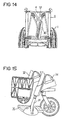
- Fig. 1 is a side view of an inventive Shown wheelchair. This includes two rear wheels 1 and two steerable front wheels 2, each on a side part 5 are stored. Furthermore, a seat 3 and a backrest 4 provided with the usual upholstery can be occupied. At the top of the backrest 4 push handles 24 are formed.
- the other components, such as leg supports, braking devices, wheel covers etc. are known from the prior art, so that descriptions in this regard are dispensed with can.
- FIGS. 2 and 3 show the structure in an enlarged view of the side parts 5. These consist of a Front frame 7 and a rear frame 8.
- the front frame 7 comprises a vertical strut 25 on which a upper side tube 10 and a lower side tube 12 attached are. There is thus an essentially U-shaped one Construction.
- the rear frame 8 comprises a vertical strut 26, on which in turn an upper side tube 11 and a lower side tube 13 are attached.
- the lower side tube 13 is extended at the rear and forms an entrance tube 27th
- a scissor element (scissors) is on the side part 5 17 stored, which comprises two struts around one Axis of rotation 28 are pivotally connected to one another.
- each the struts of the scissors 17 are firmly connected to an end pipe 29, which in turn is pivotable on the lower side tube 12 or 13 is stored.
- Each of the scissor stays 17 carries at its upper end a seat tube 19, which with a Recording slot is provided (see Fig. 4), in which an edge region of a seat belt 18 can be suspended.
- the Seat belt 18 thus forms the seat surface 3 the scissors 17 two auxiliary scissors, which, as from the State of the art are known, built and a tilting of the Side parts 5 in the folded state of the wheelchair prevent. There is no description of the auxiliary scissors, since these are known from the prior art.
- Fig. 2 also shows that in the vertical tubular Strut 26 of the rear frame 8 a back tube 9 can be inserted is wearing a back belt, not shown, which in turn forms the backrest 4.
- FIGS. 2 and 3 illustrate that the side part 5 from the Front frame 7, the rear frame 8 and the back tube 9 constructed is, with a variety of mounting recesses are provided in order to be able to vary the mutual position. So is a telescopic adjustment of the top and lower side tubes 10 to 13 the distance between the two vertical struts 25 and 26 and thus the seat depth adjustable. Furthermore, by moving the back tube 9 in the vertical strut 26 the height of the backrest and the back belt can be varied.
- FIG. 3 further shows that on the upper side tube 10th or 11 seat tube bearings 16 are attached, in which, as in Fig. 4 shown, the seat tube 19 is form-fitting.
- the seat tube bearings 16 are connected to the upper side tube 10 or 11 firmly connected, while the seat tube 19 releasably latched to fold up the wheelchair if necessary.
- FIG. 1 shows an enlarged view Representation of the rear area of the rear frame 8 as well a schematic representation of a bearing element 14 for a Rear wheel. In total there are four positions in FIG Attachment of the bearing element 14 shown which the different Variants for setting the axis of rotation of the Explain rear wheel 1.
- FIG. 6 to 8 show different assembly examples with Seat depths of 400, 430 and 450 mm.
- the one shown in Fig. 6 The standard seat depth of 430 mm is achieved by assembling the Front frame and the rear frame 7, 8 (see Fig. 2 and 3) realized. This is a distance between the two struts 25, 26 set in a dimension of 470 mm, the scissors with its tail pipe 29 pushed onto the lower side pipes 12, 13 and adjusted in position by means of fixing elements 30.
- the seat belt extends over the entire length of the seat tube 19 and thus results in a seat depth of 430 mm.
- the seat tube 19 is extended by a spacer 21, so that a lower seat belt can be installed.
- spacers 22, 23 between the front frames 7 and the rear frame 8 fitted by a distance of Realize 500 mm between the struts 25, 26.
- FIGS. 9 and 10 show the attachment in a detailed view of the bearing element 14 on the respective vertical strut 26 of the rear frame 8.
- the vertical strut 26 has a plurality of recesses, through which screw connections are possible.
- the bearing element 14 is U-shaped and engages around the strut 26, see above that there is a stable and torsionally rigid connection.
- Several recesses are made in the bearing element 14, in which either a bearing bush 39 for the Rear wheel 1 can be used. That way it's additional to the adjustment of the bearing bush 14 to the strut 26 again possible to adjust the position of the rear wheel axle vary.
- bearing element 14 through a perforated plate and a front vertical strut are replaced, whereby the range of required wheel positions can be expanded is.
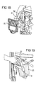
- the seat tube bearing 16 is made of glass fiber reinforced, for example Made of plastics.
- Fig. 11 further shows that in one piece with the seat tube bearing 16 a bearing sleeve 40 is formed, in which a bolt 41 one shown in Figs. 12 to 14 in detail Side part 37 can be inserted and locked.
- FIG. 12 to 14 show in different pivot positions the already mentioned side part 37, which has an armrest 36 wearing.
- the side part 37 is a bearing 42, which on rear area of the rear frame 8 is arranged so pivotable, that from the position of use shown in Fig. 12, in which the bolt 41 is received in the bearing sleeve 40 and fixed, a pivoting around a horizontal Axis is possible (see Fig. 13). After the full Swinging up the side part 37 can this one vertical axis can be pivoted behind the backrest 4 (Fig. 14).
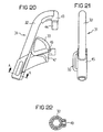
- legrest 31 each show different views the legrest 31.
- This includes an upper legrest part 32, which is in the form of a curved tube is trained.
- a vertical journal 43 is attached, which allows pivoting about a vertical axis 44.
- the bearing pin 43 is in the vertical strut 25 of the Front frame 7 releasably insertable (see in particular Fig. 16 and 17).
- the legrest 31 can thus be pivoted laterally on the one hand about getting into a wheelchair to facilitate, on the other hand in a transport position reduce the external dimensions.
- An operating part 45 is also attached to the leg support 31, which supports an operating lever 33. This is pivotable about an axis 46.
- Fig. 24 shows that a Swiveling the operating lever 33 to a displacement a spring-loaded pin 47 leads.
- the bolt 47 is in a recess on the vertical strut 25 of the Front frame 7 attached locking block 48 can be inserted, to pivot the legrest 31 in this way prevent.
- a telescopic tube 34 On the legrest upper part 32 there is also a telescopic tube 34 stored, which with a polygonal, for example hexagonal cross section is provided to prevent twisting to prevent (see Fig. 22). About set screws 49 can the telescopic position of the telescopic tube 34 is continuously adjusted become.
- the telescopic tube 34 carries on its lower End area a foot plate 35 which can be pivoted in the usual way is.
- the legrest therefore has the advantage that it can be unlocked in any position, the unlocking is done in the simplest way by pivoting the operating lever 33.
- This is loop-shaped and therefore easy to operate even for the disabled, still it protrudes laterally (see Fig. 21), so that it is special is easy to grasp. Easy intervention and pulling thus leads to a pivoting of the operating lever 33.
- FIGS. 15 to 19 show the legrest swivels both inwards and outwards and be removed in the simplest way.
- the invention relates to a wheelchair with a Frame on which rear wheels 1 and front wheels 2 are mounted and which have a seat 3 and a backrest 4 carries, the frame two mutually parallel side parts 5 includes which for folding the wheelchair in their mutual distance can be changed and by means of a scissor element 17 are connected to each other, wherein the side part 5 from individual modules is constructed.
Landscapes
- Health & Medical Sciences (AREA)
- Life Sciences & Earth Sciences (AREA)
- Animal Behavior & Ethology (AREA)
- General Health & Medical Sciences (AREA)
- Public Health (AREA)
- Veterinary Medicine (AREA)
- Handcart (AREA)
- Developing Agents For Electrophotography (AREA)
- Seats For Vehicles (AREA)
- Prostheses (AREA)
- Medicines Containing Material From Animals Or Micro-Organisms (AREA)
- Materials For Medical Uses (AREA)
Claims (9)
- Fauteuil roulant comportant un cadre, sur lequel des roues arrière (1) et des roues avant (2) sont montées et qui supporte une surface de siège (3) ainsi qu'un dossier (4), dans lequel le cadre comprend deux parties latérales (5) parallèles l'une à l'autre, qui sont variables dans leur distance réciproque pour le pliage du fauteuil roulant et sont reliées l'une à l'autre au moyen d'un élément en ciseau (17), chaque partie latérale (5) étant constituée de modules individuels qui comprennent un cadre avant (7), un cadre arrière (8) et des tubes de dos (9), qui sont respectivement reliés les uns aux autres, dans lequel le cadre avant (7) et le cadre arrière (8) comprennent chacun un tube latéral supérieur (10, 11) et un tube latéral inférieur (12, 13), qui sont disposés parallèlement l'un à l'autre, les deux tubes latéraux supérieurs (10, 11) et les deux tubes latéraux inférieurs (12, 13) peuvent être montés en plusieurs agencements l'un par rapport à l'autre pour le montage du cadre avant (7) et du cadre arrière (8) à une distance variable, du fait que les tubes latéraux supérieurs (11) respectifs du cadre arrière (8) sont guidés de manière télescopique dans les tubes latéraux supérieurs (10) du cadre avant (7) de même que les tubes latéraux inférieurs (13) du cadre arrière (8) sont guidés de manière télescopique dans les tubes latéraux inférieurs (12) du cadre avant (7), et dans lequel l'élément en ciseau (17) est monté de manière pivotante sur les tubes latéraux inférieurs (12) respectifs du cadre avant (7), au moyen d'un tube d'extrémité (29) respectif et est maintenu sur celui-ci au moyen d'un élément de fixation (30), et dans lequel, sur les tubes latéraux supérieurs (10, 12) respectifs, sont montés avec une distance variable des paliers (16) de tubes de siège, dans lesquels des tubes de siège (19) reliés avec l'élément en ciseau (17) et disposés parallèlement aux tubes latéraux (10, 12), sont maintenus par verrouillage géométrique, lesdits tubes de siège supportant une ceinture de siège (18), caractérisé en ce que les tubes d'extrémité respectifs (29) sont maintenus seulement sur les tubes latéraux (12) du cadre avant (7) à l'aide des éléments de fixation (30) à leurs deux extrémités et que les paliers (16) de tubes de siège dans lesquels les tubes de siège (19) peuvent être maintenus par enclenchement sont disposés seulement sur le cadre avant (7).
- Fauteuil roulant selon la revendication 1, caractérisé en ce que les paliers (16) de tubes de siège peuvent être montés respectivement à distance de la zone d'extrémité avant et arrière du cadre avant (7).
- Fauteuil roulant selon la revendication 1 ou 2, caractérisé en ce que la ceinture de siège (18) peut être positionnée au moyen d'une pièce d'écartement (20) sur chaque tube de siège (19) et/ou le tube de siège (19) est prolongé par une pièce d'écartement (21).
- Fauteuil roulant selon une des revendications 1 à 3, dans lequel chaque cadre avant (7) présente respectivement des moyens de montage d'un appui de jambe (31) comportant un palier pivotant à axe de pivotement sensiblement vertical, sur lequel est montée une pièce supérieure (32) d'appui de jambe, qui est à fixer près de la roue arrière (1) voisine, par un dispositif d'arrêt détachable, respectivement dans une position de translation et dans une position de transport, le palier pivotant pour la pièce supérieure (32) d'appui de jambe étant formé par un montant vertical (25) du cadre avant (7), qui relie l'un à l'autre les tubes latéraux supérieur et inférieur (10, 12).
- Fauteuil roulant selon la revendication 4, caractérisé en ce que le dispositif d'arrêt détachable présente un levier de commande (33) sous la forme d'une prise fermée.
- Fauteuil roulant selon une des revendications 4 et 5, caractérisé en ce que la pièce supérieure (32) d'appui de jambe est reliée avec un tube télescopique (34) dont la zone inférieure porte un repose-pied (35), dans lequel le tube télescopique (34) est réglable continûment.
- Fauteuil roulant selon la revendication 6, caractérisé en ce que le tube télescopique (34) est muni d'un profil intérieur pour empêcher le pivotement.
- Fauteuil roulant selon la revendication 4, caractérisé en ce que sur le montant vertical (25) est disposé aussi un logement de tête de direction pour la roue avant (2).
- Fauteuil roulant selon une des revendications 1 à 8, dans lequel est disposée de chaque côté sur le cadre, une pièce latérale respective (37) supportant un accoudoir (36), qui est maintenue dans la zone du cadre avant (7) au moyen d'un dispositif d'enclenchement détachable, la pièce latérale (37) étant montée au niveau de sa zone arrière de manière pivotante autour d'un axe vertical et d'un axe horizontal sur le cadre arrière (8), et dont la zone avant est maintenue par enclenchement sur le cadre avant (7).
Priority Applications (1)
| Application Number | Priority Date | Filing Date | Title |
|---|---|---|---|
| DE29724574U DE29724574U1 (de) | 1996-09-04 | 1997-09-02 | Rollstuhl |
Applications Claiming Priority (2)
| Application Number | Priority Date | Filing Date | Title |
|---|---|---|---|
| DE19635898 | 1996-09-04 | ||
| DE19635898 | 1996-09-04 |
Publications (3)
| Publication Number | Publication Date |
|---|---|
| EP0827729A2 EP0827729A2 (fr) | 1998-03-11 |
| EP0827729A3 EP0827729A3 (fr) | 1998-11-11 |
| EP0827729B1 true EP0827729B1 (fr) | 2003-01-15 |
Family
ID=7804618
Family Applications (1)
| Application Number | Title | Priority Date | Filing Date |
|---|---|---|---|
| EP97115207A Expired - Lifetime EP0827729B1 (fr) | 1996-09-04 | 1997-09-02 | Fauteuil roulant |
Country Status (5)
| Country | Link |
|---|---|
| EP (1) | EP0827729B1 (fr) |
| AT (1) | ATE230967T1 (fr) |
| DE (1) | DE59709131D1 (fr) |
| DK (1) | DK0827729T3 (fr) |
| ES (1) | ES2188833T3 (fr) |
Cited By (1)
| Publication number | Priority date | Publication date | Assignee | Title |
|---|---|---|---|---|
| CN102895076A (zh) * | 2012-11-06 | 2013-01-30 | 江苏亚希维医疗器械有限责任公司 | 可伸缩调节式轮椅 |
Families Citing this family (12)
| Publication number | Priority date | Publication date | Assignee | Title |
|---|---|---|---|---|
| DE29724074U1 (de) * | 1997-06-20 | 1999-11-25 | Invacare Deutschland Gmbh | Rollstuhl |
| DE19742267C2 (de) * | 1997-09-25 | 1999-10-21 | Bock Orthopaed Ind | Kreuzstrebe für einen Faltrollstuhl |
| DE29718536U1 (de) * | 1997-10-18 | 1998-02-19 | Sopur Medizintechnik Gmbh | Faltrollstuhl |
| DE19932110C1 (de) * | 1999-07-09 | 2000-08-24 | Invacare Deutschland Gmbh | Rollstuhl |
| BE1015462A3 (nl) * | 2003-04-09 | 2005-04-05 | Vermeiren Nv | Verbeterde rolstoel. |
| DE202004005653U1 (de) * | 2004-04-08 | 2004-07-15 | Meyra Wilhelm Meyer Gmbh & Co. Kg | Rollstuhlrahmen |
| FR2880798B1 (fr) * | 2005-01-14 | 2007-04-13 | Dupont Medical Sa | Fauteuil roulant |
| EP1797852A1 (fr) * | 2005-12-16 | 2007-06-20 | Invacare International Sàrl | Fauteuil roulant |
| US7635142B2 (en) * | 2006-02-01 | 2009-12-22 | Ki Mobility Llc | Latching mechanism for a wheelchair foot rest assembly |
| EP2140846B1 (fr) * | 2008-07-03 | 2011-04-06 | Invacare International Sàrl | Fauteuil roulant pliable |
| US20110018221A1 (en) * | 2009-07-27 | 2011-01-27 | Benjamin A Anooshian | Wheelchair having reversible seat rail support structure |
| ES2884118T3 (es) * | 2017-12-19 | 2021-12-10 | Permobil Ab | Mecanismo de liberación de soporte para las piernas y silla de ruedas que comprende el mismo |
Family Cites Families (6)
| Publication number | Priority date | Publication date | Assignee | Title |
|---|---|---|---|---|
| US3854774A (en) * | 1973-08-06 | 1974-12-17 | Gendron Diemer Inc | Swing-away footrest for invalid wheelchairs |
| US3883175A (en) * | 1973-08-23 | 1975-05-13 | Everest & Jennings | Swing-back detachable wheelchair armrest |
| DE3061731D1 (en) * | 1979-04-03 | 1983-03-03 | Vessa Ltd | Wheelchair and method of manufacturing it |
| US4813693A (en) * | 1986-09-30 | 1989-03-21 | Invacare Corporation | Adjustable child's wheelchair |
| GB2238275B (en) * | 1989-11-24 | 1993-09-15 | E W Marshall & Son Ltd | Wheel chairs |
| DE9110086U1 (fr) * | 1991-08-15 | 1991-10-17 | Uniroll Rollstuehle Und Rehabilitationsmittel Vertrieb - Montage Gmbh, 7517 Waldbronn, De |
-
1997
- 1997-09-02 DK DK97115207T patent/DK0827729T3/da active
- 1997-09-02 ES ES97115207T patent/ES2188833T3/es not_active Expired - Lifetime
- 1997-09-02 DE DE59709131T patent/DE59709131D1/de not_active Expired - Lifetime
- 1997-09-02 EP EP97115207A patent/EP0827729B1/fr not_active Expired - Lifetime
- 1997-09-02 AT AT97115207T patent/ATE230967T1/de active
Cited By (1)
| Publication number | Priority date | Publication date | Assignee | Title |
|---|---|---|---|---|
| CN102895076A (zh) * | 2012-11-06 | 2013-01-30 | 江苏亚希维医疗器械有限责任公司 | 可伸缩调节式轮椅 |
Also Published As
| Publication number | Publication date |
|---|---|
| DE59709131D1 (de) | 2003-02-20 |
| EP0827729A2 (fr) | 1998-03-11 |
| ES2188833T3 (es) | 2003-07-01 |
| ATE230967T1 (de) | 2003-02-15 |
| DK0827729T3 (da) | 2003-05-05 |
| EP0827729A3 (fr) | 1998-11-11 |
Similar Documents
| Publication | Publication Date | Title |
|---|---|---|
| EP0911009B2 (fr) | Fauteuil roulant avec cadre fermé en trois dimensions | |
| DE2951995C2 (de) | Segelfahrzeug für festen Untergrund | |
| EP0842844B1 (fr) | Siège de véhicule | |
| EP0827729B1 (fr) | Fauteuil roulant | |
| EP0887064A2 (fr) | Fauteuil roulant avec support de roue avant, fauteuil roulant avec assise réglable en inclinaison, fauteuil roulant avec inlinaison réglable des axes de roue arrière, siège modulaire pour fauteuil roulant, utilisation de ce siège modulaire et utilisation de ce fauteuil roulant | |
| DE3327783A1 (de) | Rollstuhl | |
| DE4137034A1 (de) | Rollstuhl mit zusammengesetztem rahmen | |
| EP1362763A2 (fr) | Voiture d'enfant, en particulier pour la rééducation | |
| EP2106777B1 (fr) | Fauteuil roulant | |
| EP3172112B1 (fr) | Poussette | |
| DE202013002877U1 (de) | Rollstuhl mit verstellbarer Sitzeinheit | |
| EP1598041B1 (fr) | Fauteuil roulant | |
| DE60218731T2 (de) | Rollstuhl | |
| DE2200988A1 (de) | Rollstuhl,der in Treppen verwendet werden kann | |
| DE10013564C1 (de) | Rollstuhl | |
| DE3136099A1 (de) | Rollstuhl | |
| DE102016102465B4 (de) | Rahmen für einen Fahrradanhänger oder Kinderwagen | |
| DE102011050800B4 (de) | Rollstuhl, Kreuzstrebenanordnung für einen Rollstuhl und Verfahren zur Einstellung des Seitenrahmenabstandes | |
| EP0911012A2 (fr) | Fauteuil roulant pliable | |
| EP1346900A1 (fr) | Voiture d'enfant | |
| EP1772129B1 (fr) | Cadre de fauteuil roulant | |
| DE4016687A1 (de) | Sitzanordnung in fahrzeugen, insbesondere personenkraftfahrzeugen | |
| DE102021001506B3 (de) | Höhenverstellbare Schubkarre | |
| EP4088986B1 (fr) | Voiture d'enfant | |
| WO1999007257A2 (fr) | Siege |
Legal Events
| Date | Code | Title | Description |
|---|---|---|---|
| PUAI | Public reference made under article 153(3) epc to a published international application that has entered the european phase |
Free format text: ORIGINAL CODE: 0009012 |
|
| AK | Designated contracting states |
Kind code of ref document: A2 Designated state(s): AT BE CH DE DK ES FR GB IT LI NL PT SE |
|
| AX | Request for extension of the european patent |
Free format text: AL;LT;LV;RO;SI |
|
| PUAL | Search report despatched |
Free format text: ORIGINAL CODE: 0009013 |
|
| AK | Designated contracting states |
Kind code of ref document: A3 Designated state(s): AT BE CH DE DK ES FI FR GB GR IE IT LI LU MC NL PT SE |
|
| AX | Request for extension of the european patent |
Free format text: AL;LT;LV;RO;SI |
|
| 17P | Request for examination filed |
Effective date: 19981019 |
|
| AKX | Designation fees paid |
Free format text: AT BE CH DE DK ES FR GB IT LI NL PT SE |
|
| 17Q | First examination report despatched |
Effective date: 20010420 |
|
| GRAG | Despatch of communication of intention to grant |
Free format text: ORIGINAL CODE: EPIDOS AGRA |
|
| GRAG | Despatch of communication of intention to grant |
Free format text: ORIGINAL CODE: EPIDOS AGRA |
|
| GRAH | Despatch of communication of intention to grant a patent |
Free format text: ORIGINAL CODE: EPIDOS IGRA |
|
| GRAH | Despatch of communication of intention to grant a patent |
Free format text: ORIGINAL CODE: EPIDOS IGRA |
|
| GRAA | (expected) grant |
Free format text: ORIGINAL CODE: 0009210 |
|
| AK | Designated contracting states |
Kind code of ref document: B1 Designated state(s): AT BE CH DE DK ES FR GB IT LI NL PT SE |
|
| PG25 | Lapsed in a contracting state [announced via postgrant information from national office to epo] |
Ref country code: GB Free format text: LAPSE BECAUSE OF FAILURE TO SUBMIT A TRANSLATION OF THE DESCRIPTION OR TO PAY THE FEE WITHIN THE PRESCRIBED TIME-LIMIT Effective date: 20030115 |
|
| REG | Reference to a national code |
Ref country code: GB Ref legal event code: FG4D Free format text: NOT ENGLISH Ref country code: CH Ref legal event code: EP |
|
| REF | Corresponds to: |
Ref document number: 59709131 Country of ref document: DE Date of ref document: 20030220 Kind code of ref document: P |
|
| REG | Reference to a national code |
Ref country code: CH Ref legal event code: NV Representative=s name: PATENTANWAELTE BREITER + WIEDMER AG |
|
| PG25 | Lapsed in a contracting state [announced via postgrant information from national office to epo] |
Ref country code: SE Free format text: LAPSE BECAUSE OF FAILURE TO SUBMIT A TRANSLATION OF THE DESCRIPTION OR TO PAY THE FEE WITHIN THE PRESCRIBED TIME-LIMIT Effective date: 20030415 Ref country code: PT Free format text: LAPSE BECAUSE OF FAILURE TO SUBMIT A TRANSLATION OF THE DESCRIPTION OR TO PAY THE FEE WITHIN THE PRESCRIBED TIME-LIMIT Effective date: 20030415 |
|
| REG | Reference to a national code |
Ref country code: DK Ref legal event code: T3 |
|
| REG | Reference to a national code |
Ref country code: ES Ref legal event code: FG2A Ref document number: 2188833 Country of ref document: ES Kind code of ref document: T3 |
|
| GBV | Gb: ep patent (uk) treated as always having been void in accordance with gb section 77(7)/1977 [no translation filed] |
Effective date: 20030115 |
|
| ET | Fr: translation filed | ||
| PLBE | No opposition filed within time limit |
Free format text: ORIGINAL CODE: 0009261 |
|
| STAA | Information on the status of an ep patent application or granted ep patent |
Free format text: STATUS: NO OPPOSITION FILED WITHIN TIME LIMIT |
|
| 26N | No opposition filed |
Effective date: 20031016 |
|
| REG | Reference to a national code |
Ref country code: CH Ref legal event code: PFA Owner name: MEYRA WILHELM MEYER GMBH & CO. KG Free format text: MEYRA WILHELM MEYER GMBH & CO. KG#MEYRA-RING 2#D-32689 KALLETAL-KALLDORF (DE) -TRANSFER TO- MEYRA WILHELM MEYER GMBH & CO. KG#MEYRA-RING 2#D-32689 KALLETAL-KALLDORF (DE) |
|
| PGFP | Annual fee paid to national office [announced via postgrant information from national office to epo] |
Ref country code: DK Payment date: 20110926 Year of fee payment: 15 |
|
| PGFP | Annual fee paid to national office [announced via postgrant information from national office to epo] |
Ref country code: ES Payment date: 20120924 Year of fee payment: 16 Ref country code: IT Payment date: 20120926 Year of fee payment: 16 |
|
| PGFP | Annual fee paid to national office [announced via postgrant information from national office to epo] |
Ref country code: BE Payment date: 20120919 Year of fee payment: 16 Ref country code: NL Payment date: 20120920 Year of fee payment: 16 |
|
| REG | Reference to a national code |
Ref country code: DE Ref legal event code: R082 Ref document number: 59709131 Country of ref document: DE Representative=s name: HOEFER & PARTNER PATENTANWAELTE MBB, DE Ref country code: DE Ref legal event code: R082 Ref document number: 59709131 Country of ref document: DE Representative=s name: HOEFER & PARTNER, DE Ref country code: DE Ref legal event code: R082 Ref document number: 59709131 Country of ref document: DE |
|
| BERE | Be: lapsed |
Owner name: *MEYRA WILHELM MEYER G.M.B.H. & CO. K.G. Effective date: 20130930 |
|
| REG | Reference to a national code |
Ref country code: NL Ref legal event code: V1 Effective date: 20140401 |
|
| REG | Reference to a national code |
Ref country code: DK Ref legal event code: EBP Effective date: 20130930 |
|
| PG25 | Lapsed in a contracting state [announced via postgrant information from national office to epo] |
Ref country code: BE Free format text: LAPSE BECAUSE OF NON-PAYMENT OF DUE FEES Effective date: 20130930 |
|
| PG25 | Lapsed in a contracting state [announced via postgrant information from national office to epo] |
Ref country code: IT Free format text: LAPSE BECAUSE OF NON-PAYMENT OF DUE FEES Effective date: 20130902 Ref country code: NL Free format text: LAPSE BECAUSE OF NON-PAYMENT OF DUE FEES Effective date: 20140401 |
|
| PG25 | Lapsed in a contracting state [announced via postgrant information from national office to epo] |
Ref country code: DK Free format text: LAPSE BECAUSE OF NON-PAYMENT OF DUE FEES Effective date: 20130930 |
|
| PGFP | Annual fee paid to national office [announced via postgrant information from national office to epo] |
Ref country code: CH Payment date: 20140922 Year of fee payment: 18 |
|
| REG | Reference to a national code |
Ref country code: ES Ref legal event code: FD2A Effective date: 20141107 |
|
| PGFP | Annual fee paid to national office [announced via postgrant information from national office to epo] |
Ref country code: AT Payment date: 20140630 Year of fee payment: 18 |
|
| PG25 | Lapsed in a contracting state [announced via postgrant information from national office to epo] |
Ref country code: ES Free format text: LAPSE BECAUSE OF NON-PAYMENT OF DUE FEES Effective date: 20130903 |
|
| PGFP | Annual fee paid to national office [announced via postgrant information from national office to epo] |
Ref country code: FR Payment date: 20140917 Year of fee payment: 18 |
|
| REG | Reference to a national code |
Ref country code: CH Ref legal event code: PCAR Free format text: NEW ADDRESS: EIGERSTRASSE 2 POSTFACH, 3000 BERN 14 (CH) |
|
| PGFP | Annual fee paid to national office [announced via postgrant information from national office to epo] |
Ref country code: DE Payment date: 20150930 Year of fee payment: 19 |
|
| REG | Reference to a national code |
Ref country code: CH Ref legal event code: PL |
|
| REG | Reference to a national code |
Ref country code: AT Ref legal event code: MM01 Ref document number: 230967 Country of ref document: AT Kind code of ref document: T Effective date: 20150902 |
|
| REG | Reference to a national code |
Ref country code: FR Ref legal event code: ST Effective date: 20160531 |
|
| PG25 | Lapsed in a contracting state [announced via postgrant information from national office to epo] |
Ref country code: LI Free format text: LAPSE BECAUSE OF NON-PAYMENT OF DUE FEES Effective date: 20150930 Ref country code: CH Free format text: LAPSE BECAUSE OF NON-PAYMENT OF DUE FEES Effective date: 20150930 |
|
| PG25 | Lapsed in a contracting state [announced via postgrant information from national office to epo] |
Ref country code: AT Free format text: LAPSE BECAUSE OF NON-PAYMENT OF DUE FEES Effective date: 20150902 Ref country code: FR Free format text: LAPSE BECAUSE OF NON-PAYMENT OF DUE FEES Effective date: 20150930 |
|
| REG | Reference to a national code |
Ref country code: DE Ref legal event code: R119 Ref document number: 59709131 Country of ref document: DE |
|
| PG25 | Lapsed in a contracting state [announced via postgrant information from national office to epo] |
Ref country code: DE Free format text: LAPSE BECAUSE OF NON-PAYMENT OF DUE FEES Effective date: 20170401 |