EP0827706A2 - Changing table - Google Patents
Changing table Download PDFInfo
- Publication number
- EP0827706A2 EP0827706A2 EP97420142A EP97420142A EP0827706A2 EP 0827706 A2 EP0827706 A2 EP 0827706A2 EP 97420142 A EP97420142 A EP 97420142A EP 97420142 A EP97420142 A EP 97420142A EP 0827706 A2 EP0827706 A2 EP 0827706A2
- Authority
- EP
- European Patent Office
- Prior art keywords
- tray
- opening
- changing table
- stud
- edges
- Prior art date
- Legal status (The legal status is an assumption and is not a legal conclusion. Google has not performed a legal analysis and makes no representation as to the accuracy of the status listed.)
- Withdrawn
Links
- 230000003014 reinforcing effect Effects 0.000 claims description 3
- 230000006978 adaptation Effects 0.000 description 4
- 239000004033 plastic Substances 0.000 description 3
- 229920003023 plastic Polymers 0.000 description 3
- 238000012423 maintenance Methods 0.000 description 2
- 239000000463 material Substances 0.000 description 2
- -1 polypropylene Polymers 0.000 description 2
- 241000287107 Passer Species 0.000 description 1
- 239000004698 Polyethylene Substances 0.000 description 1
- 239000004743 Polypropylene Substances 0.000 description 1
- 241001080024 Telles Species 0.000 description 1
- 240000008042 Zea mays Species 0.000 description 1
- 210000004027 cell Anatomy 0.000 description 1
- 238000006073 displacement reaction Methods 0.000 description 1
- 210000005069 ears Anatomy 0.000 description 1
- 238000000034 method Methods 0.000 description 1
- 210000000056 organ Anatomy 0.000 description 1
- 229920000573 polyethylene Polymers 0.000 description 1
- 229920000098 polyolefin Polymers 0.000 description 1
- 229920001155 polypropylene Polymers 0.000 description 1
- 239000000344 soap Substances 0.000 description 1
- 238000003856 thermoforming Methods 0.000 description 1
Images


Classifications
-
- A—HUMAN NECESSITIES
- A47—FURNITURE; DOMESTIC ARTICLES OR APPLIANCES; COFFEE MILLS; SPICE MILLS; SUCTION CLEANERS IN GENERAL
- A47D—FURNITURE SPECIALLY ADAPTED FOR CHILDREN
- A47D5/00—Dressing-tables or diaper changing supports for children
Definitions
- the invention relates to a new changing table of the type comprising a tray suitable for receiving a changing mat.
- the invention overcomes these drawbacks. It aims at a changing plan of the type in question which is perfectly adapted whatever the dimensions of the opening of the organ intended to receive it.
- the invention relates to a changing table comprising a tray capable of receiving a changing mat, intended to be fitted on top of an opening, in particular the top of a bathtub or a cage bed, and in which the underside of the plate has means capable of wedging said plate on the edges of the opening, characterized in that these means are adjustable in position and lockable on the edges of the opening.
- the plate has on both main lateral edges of the longitudinal recesses intended to form tanks for storage.
- the plate is shaped general rectangular, and according to the invention said tray has lights arranged in a cross in the vicinity of each of its four angles and the means of adjustment and locking features are able to slide and lock in said lights.
- the changing table according to the invention is made of thermoformed plastic.
- Figure 1 is a top view of a preferred embodiment of the plan to changing according to the invention shown in section along axis II-II 'in Figure 2 and view of side in Figure 3.
- Figure 4 is a side view of a locking pin characteristic of the invention shown seen from above in Figure 5.
- Figures 6 and 7 show respectively in the unlocked position ( Figure 6) and in the locked position ( Figure 7) the means of adjustment and locking by coincident cleat in figure 4.
- Figure 8 is a perspective view showing the elements separately adjustment and locking means.
- the changing plan according to the invention designated by the general reference (1) is made by thermoforming in plastic material polyolefin, such as polypropylene or polyethylene.
- This changing table (1) includes a tray (2) capable of receiving a mattress changing not shown, commonly used for this application.
- This changing table is intended to be fitted on top of an opening, such as the edges of a bathtub (B1, B2) or a cage bed (L1, L2).
- the plate (2) has on the two main lateral edges (3,4) recesses (5,6) intended to form storage bins for various objects, such like sponges, brushes, soaps, etc.
- the plate (2) is of general shape rectangular and has four lights at each of its four angles (10,11,12,13). More precisely, the underside of the tray (see Figure 2) has two reinforcing ribs (15,16) in X, the ends of which have said lights (10-13). These lights (10-13) cooperate with a means of adjustment and locking characteristic of the invention.
- the stud (21) has a lateral lug (50) orthogonal to the plan of the stud, intended to serve as a stop to pass under the upper crosspieces of a cot and thus ensure good maintenance of the changing table.
- the rear side face vertical of the changing table has openings intended to receive suction cups (60) which are intended to be pressed against the vertical wall generally tiled overhanging the bath, and thereby ensuring good support from the whole.
Abstract
Description
L'invention concerne un nouveau plan à langer du type comprenant un plateau apte à recevoir un matelas à langer.The invention relates to a new changing table of the type comprising a tray suitable for receiving a changing mat.
On connaít déjà des plans à langer destinés à être adaptés sur le dessus d'une ouverture, telle que par exemple au dessus d'une baignoire ou d'un lit-cage, dans lequel la face inférieure du plateau destinée à recevoir le matelas à langer proprement dit, présente des plots aptes à caler le plateau sur les bords de l'ouverture. Bien que largement répandue, cette solution présente l'inconvénient de n'être adaptée qu'à une seule largeur d'ouverture. Il s'ensuit une absence de versatilité selon les différentes dimensions d'ouverture, et partant, un manque de sécurité dans les conditions d'utilisation où l'ouverture est différente de celle pour laquelle le plan est prévu. En effet, un plan à langer adapté à une baignoire déterminée ne pourra pas s'adapter à un lit-cage et vice-versa (voir aussi BE-A-896 888 et EP-A-0288047).We already know changing plans intended to be adapted on top an opening, such as above a bathtub or a cot, in which the underside of the tray intended to receive the changing mat proper, has studs capable of wedging the plate on the edges of the opening. Although widely used, this solution has the disadvantage of be adapted to only one opening width. It follows an absence of versatility according to the different opening dimensions, and therefore a lack of safety in the conditions of use where the opening is different from that for which the plan is planned. Indeed, a changing table adapted to a bathtub determined cannot adapt to a cot and vice versa (see also BE-A-896 888 and EP-A-0288047).
L'invention pallie ces inconvénients. Elle vise un plan à langer du type en question qui soit parfaitement adapté quelles que soient les dimensions de l'ouverture de l'organe destiné à le recevoir.The invention overcomes these drawbacks. It aims at a changing plan of the type in question which is perfectly adapted whatever the dimensions of the opening of the organ intended to receive it.
L'invention concerne un plan à langer comprenant un plateau apte à recevoir un matelas à langer, destiné à être adapté sur le dessus d'une ouverture, notamment le dessus d'une baignoire ou d'un lit-cage, et dans lequel la face inférieure du plateau présente des moyens aptes à caler ledit plateau sur les bords de l'ouverture, caractérisé en ce que ces moyens sont réglables en position et verrouillables sur les bords de l'ouverture.The invention relates to a changing table comprising a tray capable of receiving a changing mat, intended to be fitted on top of an opening, in particular the top of a bathtub or a cage bed, and in which the underside of the plate has means capable of wedging said plate on the edges of the opening, characterized in that these means are adjustable in position and lockable on the edges of the opening.
Dans une première forme d'exécution, le plateau comporte sur les deux bords latéraux principaux des évidements longitudinaux destinés à former bacs de rangement. In a first embodiment, the plate has on both main lateral edges of the longitudinal recesses intended to form tanks for storage.
Dans une seconde forme d'exécution préférée, le plateau est de forme générale rectangulaire, et selon l'invention ledit plateau présente des lumières disposées en croix au voisinage de chacun de ses quatre angles et les moyens de réglage et de verrouillage caractéristiques sont aptes à coulisser et à se bloquer dans lesdites lumières.In a second preferred embodiment, the plate is shaped general rectangular, and according to the invention said tray has lights arranged in a cross in the vicinity of each of its four angles and the means of adjustment and locking features are able to slide and lock in said lights.
Avantageusement, en pratique :
- les moyens de réglage et de verrouillage sont constitués par un plot
formant pied dont le fond coopère avec un taquet coïnceur, constitué
respectivement :
- d'une base venant se loger dans le fond du plot ;
- d'un bras traversant et coulissant dans une lumière ;
- d'une languette de blocage comprenant une came coopérant avec les bords de la lumière ;
- le taquet coïnceur comporte également un joint torique interposé entre la face supérieure de la base du bras et le fond du plot ;
- la face inférieure du plateau comporte deux nervures de renfort en X, dont les extrémités comportent lesdites lumières ;
- la face verticale arrière du plateau, destinée à être positionnée du côté de la tête de l'enfant à langer, présente des ouvertures aptes à recevoir une ventouse destinée à être plaquée sur la paroi verticale surplombant l'ouverture, telle que par exemple la baignoire, et par là assumer un bon maintien de l'ensemble.
- the adjustment and locking means are constituted by a stud forming a foot, the bottom of which cooperates with a coining wedge, constituted respectively:
- a base which is housed in the bottom of the stud;
- of an arm crossing and sliding in a light;
- a locking tab comprising a cam cooperating with the edges of the lumen;
- the coining pin also includes an O-ring interposed between the upper face of the base of the arm and the bottom of the stud;
- the underside of the plate has two reinforcing ribs in X, the ends of which include said slots;
- the rear vertical face of the tray, intended to be positioned on the side of the child's changing head, has openings suitable for receiving a suction cup intended to be pressed against the vertical wall overhanging the opening, such as for example the bathtub , and thereby assume good maintenance of the whole.
En pratique, d'une manière générale, le plan à langer conforme à l'invention est réalisé en matière plastique thermoformée.In practice, in general, the changing table according to the invention is made of thermoformed plastic.
La manière de réaliser l'invention peut être réalisée et les avantages qui en découlent ressortiront mieux de l'exemple de réalisation qui suit, à l'appui des figures annexées, dans lequel :The manner of carrying out the invention can be carried out and the advantages which will emerge more clearly from the example of embodiment which follows, in support of attached figures, in which:
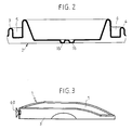
La figure 1 est une vue de dessus d'une forme d'exécution préférée du plan à langer selon l'invention montré en coupe selon l'axe II-II' à la figure 2 et vue de côté à la figure 3.Figure 1 is a top view of a preferred embodiment of the plan to changing according to the invention shown in section along axis II-II 'in Figure 2 and view of side in Figure 3.
La figure 4 est une vue de côté d'un plot de verrouillage caractéristique de l'invention montré vu de dessus à la figure 5. Figure 4 is a side view of a locking pin characteristic of the invention shown seen from above in Figure 5.
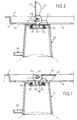
Les figures 6 et 7 représentent respectivement en position déverrouillée (figure 6) et en position verrouillée (figure 7) le moyen de réglage et de verrouillage par taquet coïnceur de la figure 4.Figures 6 and 7 show respectively in the unlocked position (Figure 6) and in the locked position (Figure 7) the means of adjustment and locking by coincident cleat in figure 4.
La figure 8 est une vue en perspective représentant séparément les éléments des moyens de réglage et de verrouillage.Figure 8 is a perspective view showing the elements separately adjustment and locking means.
En se référant à la figure 1, le plan à langer conforme à l'invention désigné par la référence générale (1) est réalisé par thermoformage en matière plastique polyoléfine, telle que polypropylène ou polyéthylène.Referring to Figure 1, the changing plan according to the invention designated by the general reference (1) is made by thermoforming in plastic material polyolefin, such as polypropylene or polyethylene.
Ce plan à langer (1) comprend un plateau (2) apte à recevoir un matelas à langer non représenté, d'usage courant pour cette application. Ce plan à langer est destiné à être adapté sur le dessus d'une ouverture, telle que les bords d'une baignoire (B1,B2) ou d'un lit-cage (L1,L2).This changing table (1) includes a tray (2) capable of receiving a mattress changing not shown, commonly used for this application. This changing table is intended to be fitted on top of an opening, such as the edges of a bathtub (B1, B2) or a cage bed (L1, L2).
Le plateau (2) présente sur les deux bords latéraux principaux (3,4) des évidements (5,6) destiné à former bacs de rangements pour des objets divers, tels que éponges, brosses, savons, etc...The plate (2) has on the two main lateral edges (3,4) recesses (5,6) intended to form storage bins for various objects, such like sponges, brushes, soaps, etc.
Dans la forme d'exécution préférée, le plateau (2) est de forme générale rectangulaire et présente à chacun de ses quatre angles quatre lumières (10,11,12,13). Plus exactement, la face inférieure du plateau (voir figure 2) présente deux nervures de renfort (15,16) en X, dont les extrémités comportent lesdites lumières (10-13). Ces lumières (10-13) coopèrent avec un moyen de réglage et de verrouillage caractéristique de l'invention.In the preferred embodiment, the plate (2) is of general shape rectangular and has four lights at each of its four angles (10,11,12,13). More precisely, the underside of the tray (see Figure 2) has two reinforcing ribs (15,16) in X, the ends of which have said lights (10-13). These lights (10-13) cooperate with a means of adjustment and locking characteristic of the invention.
Ce moyen caractéristique (voir figures 6, 7 et 8), désigné par la référence générale (20) est essentiellement formé de trois parties distinctes, à savoir respectivement :
- un plot (21) creux moulé ou thermoformé formant pied, de forme générale légèrement tronconique, et dont le fond (22) d'une part, vient s'appliquer contre la face inférieure (19) du plateau (2), et d'autre part, présente deux oreilles (23,24) disposées sur le dessus (voir figure 5), destinées à être positionnées contre les bords des rainures (15) et (16); la face interne du fond (22 ) présente une couronne cylindrique (25) dont les parois sont sensiblement parallèles à celles du plot (21), mais dont la hauteur est limitée seulement à une portion du fond ;
- un taquet coïnceur (30) également en matière plastique moulée ou injectée,
monobloc, constitué respectivement
- d'une base (31) destinée à venir se loger dans la couronne (25) en s'appuyant sur la face interne (26) du plot, d'un bras (32) orthogonal à la base (31) destiné à traverser et à coulisser dans les lumières (10-13);
- d'un axe (33) parallèle à la base (31), destiné à passer à travers l'ouverture caractéristique (27,28) ménagée sur le dessus (22), puis à dépasser les lumières (10-13);
- d'un joint torique (34) compressible, destiné à être interposé entre la face supérieure (35) de la base (31) et la face inférieure (26) du fond de la couronne (25);
- une languette de blocage (40) (voir figures 6, 7 et 8), constituée d'un levier (41) présentant à une extrémité un crochet (42) formant came destiné à s'engager dans l'axe (34); en basculant le levier (41) (voir figure 7), on comprime le joint torique (33) grâce au déplacement de la came (42) qui réhausse l'axe (33) du fait de l'escamotage du levier (41) (voir figure 7).
- a hollow molded or thermoformed stud (21) forming a foot, of generally slightly frustoconical shape, and the bottom (22) of which, on the one hand, is applied against the underside (19) of the plate (2), and on the other hand, has two ears (23,24) arranged on the top (see Figure 5), intended to be positioned against the edges of the grooves (15) and (16); the inner face of the bottom (22) has a cylindrical crown (25) whose walls are substantially parallel to those of the stud (21), but whose height is limited only to a portion of the bottom;
- a coincidenting cleat (30) also in molded or injected plastic material, in one piece, constituted respectively
- a base (31) intended to be housed in the crown (25) based on the internal face (26) of the stud, an arm (32) orthogonal to the base (31) intended to pass through and to slide in the lights (10-13);
- an axis (33) parallel to the base (31), intended to pass through the characteristic opening (27,28) formed on the top (22), then to exceed the openings (10-13);
- a compressible O-ring (34), intended to be interposed between the upper face (35) of the base (31) and the lower face (26) of the bottom of the crown (25);
- a locking tab (40) (see Figures 6, 7 and 8), consisting of a lever (41) having at one end a hook (42) forming a cam intended to engage in the axis (34); by tilting the lever (41) (see FIG. 7), the O-ring (33) is compressed by virtue of the displacement of the cam (42) which raises the axis (33) due to the retraction of the lever (41) ( see figure 7).
Lorsque l'utilisateur désire ajuster le plan à langer sur l'ouverture d'un lit-cage ou d'une baignoire, il lui suffit d'enlever le matelas à langer pour avoir accès aux taquets (30) et de faire coulisser le bras (31) dans les lumières concernées jusqu'à ce que le plot (21) vienne s'appuyer sur les bords concernés. A ce moment, de manière classique, l'utilisateur rabat le levier (41) de la languette (40) pour assurer le positionnement et le verrouillage des plots (21) contre les bords de l'ouverture concernée. En position verrouillée (voir figure 7), la languette (41) est complètement escamotée dans les nervures (15,16) de manière à ne pas former protubérance sur l'envers du matelas à langer.When the user wishes to adjust the changing table on the opening of a cot or a bathtub, just remove the changing mat to gain access to the cleats (30) and to slide the arm (31) into the lights concerned until the stud (21) comes to rest on the edges concerned. At the moment, conventionally, the user folds the lever (41) of the tongue (40) to ensure the positioning and locking of the studs (21) against the edges of the opening concerned. In the locked position (see Figure 7), the tab (41) is completely retracted into the ribs (15,16) so as not to form protrusion on the back of the changing mat.
Avantageusement, le plot (21) présente un ergot latéral (50) orthogonal au plan du plot, destiné à servir de butée pour passer sous les traverses supérieures d'un lit à barreaux et ainsi assurer un bon maintien du plan à langer.Advantageously, the stud (21) has a lateral lug (50) orthogonal to the plan of the stud, intended to serve as a stop to pass under the upper crosspieces of a cot and thus ensure good maintenance of the changing table.
Dans une version avantageuse (voir figure 3), la face latérale arrière verticale du plan à langer présente des ouvertures destinées à recevoir des ventouses (60) qui sont destinées à être plaquées contre la paroi verticale généralement carrelée surplombant la baignoire, et par là assurer un bon maintien de l'ensemble.In an advantageous version (see Figure 3), the rear side face vertical of the changing table has openings intended to receive suction cups (60) which are intended to be pressed against the vertical wall generally tiled overhanging the bath, and thereby ensuring good support from the whole.
Le plan à langer conforme à l'invention présente de nombreux avantages par rapport à ceux utilisés à ce jour. On peut citer :
- la simplicité mécanique ;
- la parfaite adaptation aux différentes dimensions des ouvertures possibles ;
- la versatilité d'adaptation ;
- la sécurité d'emploi.
- mechanical simplicity;
- perfect adaptation to the different dimensions of the possible openings;
- versatility of adaptation;
- job security.
De la sorte, il peut être utilisé avec succès dans toutes les applications des plans à langer.In this way, it can be successfully used in all applications of changing plans.
Claims (5)
Applications Claiming Priority (2)
| Application Number | Priority Date | Filing Date | Title |
|---|---|---|---|
| FR9611154 | 1996-09-06 | ||
| FR9611154A FR2753065B3 (en) | 1996-09-06 | 1996-09-06 | CHANGING PLAN |
Publications (2)
| Publication Number | Publication Date |
|---|---|
| EP0827706A2 true EP0827706A2 (en) | 1998-03-11 |
| EP0827706A3 EP0827706A3 (en) | 1999-04-21 |
Family
ID=9495695
Family Applications (1)
| Application Number | Title | Priority Date | Filing Date |
|---|---|---|---|
| EP97420142A Withdrawn EP0827706A3 (en) | 1996-09-06 | 1997-08-08 | Changing table |
Country Status (2)
| Country | Link |
|---|---|
| EP (1) | EP0827706A3 (en) |
| FR (1) | FR2753065B3 (en) |
Cited By (2)
| Publication number | Priority date | Publication date | Assignee | Title |
|---|---|---|---|---|
| EP1021977A1 (en) * | 1999-01-19 | 2000-07-26 | STAMP S.r.l. | Portable unit for changing clothes to babies or carrying out personal hygiene of same |
| WO2002009555A1 (en) * | 2000-07-28 | 2002-02-07 | Philip Royle | Baby change and bath platform |
Citations (2)
| Publication number | Priority date | Publication date | Assignee | Title |
|---|---|---|---|---|
| FR2599232A1 (en) * | 1986-05-28 | 1987-12-04 | Lemoy Patrick | Nappy-changing support which can be fitted to a bathtub |
| GB2280366A (en) * | 1993-07-30 | 1995-02-01 | David Garry Drew | Baby changing mat |
-
1996
- 1996-09-06 FR FR9611154A patent/FR2753065B3/en not_active Expired - Lifetime
-
1997
- 1997-08-08 EP EP97420142A patent/EP0827706A3/en not_active Withdrawn
Patent Citations (2)
| Publication number | Priority date | Publication date | Assignee | Title |
|---|---|---|---|---|
| FR2599232A1 (en) * | 1986-05-28 | 1987-12-04 | Lemoy Patrick | Nappy-changing support which can be fitted to a bathtub |
| GB2280366A (en) * | 1993-07-30 | 1995-02-01 | David Garry Drew | Baby changing mat |
Cited By (2)
| Publication number | Priority date | Publication date | Assignee | Title |
|---|---|---|---|---|
| EP1021977A1 (en) * | 1999-01-19 | 2000-07-26 | STAMP S.r.l. | Portable unit for changing clothes to babies or carrying out personal hygiene of same |
| WO2002009555A1 (en) * | 2000-07-28 | 2002-02-07 | Philip Royle | Baby change and bath platform |
Also Published As
| Publication number | Publication date |
|---|---|
| EP0827706A3 (en) | 1999-04-21 |
| FR2753065A3 (en) | 1998-03-13 |
| FR2753065B3 (en) | 1998-07-10 |
Similar Documents
| Publication | Publication Date | Title |
|---|---|---|
| EP0784019B1 (en) | Angular fastening device | |
| FR2638076A1 (en) | MONOLITHIC SEAT IN PLASTIC INJECTED | |
| FR2657590A1 (en) | MULTIPURPOSE BOX WITH UNIFORM EXTERNAL SURFACE. | |
| EP2394547B1 (en) | Electrical kitchen appliance comprising a work container sealed by a removable cover | |
| BE1005930A3 (en) | Necesary FOR PUZZLE BOX CRUST. | |
| FR2476329A1 (en) | BOX FOR SAME SIZE VIEWS | |
| FR2626453A1 (en) | BOX | |
| FR2838622A1 (en) | Tray system for high chair used by e.g. infant, toddler, adult in e.g. hospital, nursing home, has auxiliary tray, coupled to bottom side of main tray, which can move under portion of main tray | |
| EP0494021B1 (en) | Hinged sponge mob | |
| FR2764564A1 (en) | VEHICLE SEAT HAVING AN INTEGRATED ARMREST IN THE SEAT | |
| EP0502281B1 (en) | Device for attaching a means of identification to receptacles such as pots used in cultivating horticultural plants | |
| FR2499914A1 (en) | CAR ROOF WITH SLIDING AND RELEVABLE PANEL | |
| EP0827706A2 (en) | Changing table | |
| FR2896969A1 (en) | Contour changing pad for changing diaper of baby, has upper part inclined by raising unit, where part receives foot of baby inclined with respect to horizontal base part with inclination opposite to inclination of upper part | |
| FR2643046A1 (en) | SEALED CONTAINER FOR USE IN PARTICULAR FOOD | |
| WO2004003395A2 (en) | Device for fixing an object on a vertical rod | |
| EP0128810A1 (en) | Luggage device for motor bicycles or the like | |
| EP0208636A2 (en) | Lounge-chair | |
| EP0287583A1 (en) | Bracelet fastener. | |
| FR2586916A3 (en) | Stackable chair | |
| FR2797395A1 (en) | Waist fastenings, for disposable diaper, comprise interlocking male and female components | |
| EP2397367A1 (en) | Space organiser for a vehicle | |
| FR2745167A1 (en) | Structure for supporting bath or shower base | |
| FR2758074A1 (en) | GRIPPING DEVICE FOR COOKING UTENSILS | |
| FR2724813A1 (en) | Plant container having water reservoir |
Legal Events
| Date | Code | Title | Description |
|---|---|---|---|
| PUAI | Public reference made under article 153(3) epc to a published international application that has entered the european phase |
Free format text: ORIGINAL CODE: 0009012 |
|
| AK | Designated contracting states |
Kind code of ref document: A2 Designated state(s): AT BE CH DE DK ES FI FR GB GR IE IT LI LU MC NL PT SE |
|
| PUAL | Search report despatched |
Free format text: ORIGINAL CODE: 0009013 |
|
| AK | Designated contracting states |
Kind code of ref document: A3 Designated state(s): AT BE CH DE DK ES FI FR GB GR IE IT LI LU MC NL PT SE |
|
| AKX | Designation fees paid | ||
| REG | Reference to a national code |
Ref country code: DE Ref legal event code: 8566 |
|
| STAA | Information on the status of an ep patent application or granted ep patent |
Free format text: STATUS: THE APPLICATION IS DEEMED TO BE WITHDRAWN |
|
| 18D | Application deemed to be withdrawn |
Effective date: 19991022 |