EP0827217A2 - Oxide superconductor wire material and method for jointing the same together - Google Patents
Oxide superconductor wire material and method for jointing the same together Download PDFInfo
- Publication number
- EP0827217A2 EP0827217A2 EP97115103A EP97115103A EP0827217A2 EP 0827217 A2 EP0827217 A2 EP 0827217A2 EP 97115103 A EP97115103 A EP 97115103A EP 97115103 A EP97115103 A EP 97115103A EP 0827217 A2 EP0827217 A2 EP 0827217A2
- Authority
- EP
- European Patent Office
- Prior art keywords
- wire material
- oxide superconductor
- tape
- superconductor wire
- silver
- Prior art date
- Legal status (The legal status is an assumption and is not a legal conclusion. Google has not performed a legal analysis and makes no representation as to the accuracy of the status listed.)
- Withdrawn
Links
- 239000000463 material Substances 0.000 title claims abstract description 198
- 239000002887 superconductor Substances 0.000 title claims abstract description 121
- 238000000034 method Methods 0.000 title claims description 47
- 239000013078 crystal Substances 0.000 claims abstract description 32
- 239000002184 metal Substances 0.000 claims abstract description 15
- 229910052751 metal Inorganic materials 0.000 claims abstract description 14
- 239000010949 copper Substances 0.000 claims description 109
- 239000004332 silver Substances 0.000 claims description 33
- 229910052709 silver Inorganic materials 0.000 claims description 32
- 229910001020 Au alloy Inorganic materials 0.000 claims description 17
- 239000003353 gold alloy Substances 0.000 claims description 17
- 239000011248 coating agent Substances 0.000 claims description 15
- 238000000576 coating method Methods 0.000 claims description 15
- PQTCMBYFWMFIGM-UHFFFAOYSA-N gold silver Chemical compound [Ag].[Au] PQTCMBYFWMFIGM-UHFFFAOYSA-N 0.000 claims description 11
- 238000002844 melting Methods 0.000 claims description 11
- 230000008018 melting Effects 0.000 claims description 11
- 238000007669 thermal treatment Methods 0.000 claims description 11
- PXHVJJICTQNCMI-UHFFFAOYSA-N Nickel Chemical compound [Ni] PXHVJJICTQNCMI-UHFFFAOYSA-N 0.000 claims description 10
- 229910045601 alloy Inorganic materials 0.000 claims description 9
- 239000000956 alloy Substances 0.000 claims description 9
- 239000000155 melt Substances 0.000 claims description 6
- FYYHWMGAXLPEAU-UHFFFAOYSA-N Magnesium Chemical compound [Mg] FYYHWMGAXLPEAU-UHFFFAOYSA-N 0.000 claims description 5
- 229910052749 magnesium Inorganic materials 0.000 claims description 5
- 239000011777 magnesium Substances 0.000 claims description 5
- 229910052759 nickel Inorganic materials 0.000 claims description 5
- 230000002085 persistent effect Effects 0.000 claims description 5
- 229910052782 aluminium Inorganic materials 0.000 claims description 4
- XAGFODPZIPBFFR-UHFFFAOYSA-N aluminium Chemical compound [Al] XAGFODPZIPBFFR-UHFFFAOYSA-N 0.000 claims description 4
- 239000004411 aluminium Substances 0.000 claims description 3
- 238000004519 manufacturing process Methods 0.000 claims description 3
- BQCADISMDOOEFD-UHFFFAOYSA-N Silver Chemical compound [Ag] BQCADISMDOOEFD-UHFFFAOYSA-N 0.000 description 31
- 229910002480 Cu-O Inorganic materials 0.000 description 16
- 239000000126 substance Substances 0.000 description 14
- 239000012071 phase Substances 0.000 description 13
- 239000000843 powder Substances 0.000 description 13
- 230000002829 reductive effect Effects 0.000 description 9
- 230000005540 biological transmission Effects 0.000 description 8
- 239000007788 liquid Substances 0.000 description 8
- 238000011049 filling Methods 0.000 description 6
- 239000001307 helium Substances 0.000 description 6
- 229910052734 helium Inorganic materials 0.000 description 6
- SWQJXJOGLNCZEY-UHFFFAOYSA-N helium atom Chemical compound [He] SWQJXJOGLNCZEY-UHFFFAOYSA-N 0.000 description 6
- 230000036961 partial effect Effects 0.000 description 6
- 238000007711 solidification Methods 0.000 description 6
- 230000008023 solidification Effects 0.000 description 6
- 238000005481 NMR spectroscopy Methods 0.000 description 5
- 239000004020 conductor Substances 0.000 description 5
- 230000006866 deterioration Effects 0.000 description 5
- 230000000694 effects Effects 0.000 description 5
- 239000011159 matrix material Substances 0.000 description 5
- 230000000052 comparative effect Effects 0.000 description 4
- 238000001816 cooling Methods 0.000 description 4
- PCHJSUWPFVWCPO-UHFFFAOYSA-N gold Chemical compound [Au] PCHJSUWPFVWCPO-UHFFFAOYSA-N 0.000 description 4
- 229910052737 gold Inorganic materials 0.000 description 4
- 239000010931 gold Substances 0.000 description 4
- 238000010438 heat treatment Methods 0.000 description 4
- 239000000203 mixture Substances 0.000 description 4
- 238000012545 processing Methods 0.000 description 4
- 239000007791 liquid phase Substances 0.000 description 3
- 239000002245 particle Substances 0.000 description 3
- 229910052692 Dysprosium Inorganic materials 0.000 description 2
- 229910052691 Erbium Inorganic materials 0.000 description 2
- 229910052693 Europium Inorganic materials 0.000 description 2
- 229910052688 Gadolinium Inorganic materials 0.000 description 2
- 229910052689 Holmium Inorganic materials 0.000 description 2
- 229910052765 Lutetium Inorganic materials 0.000 description 2
- 229910052779 Neodymium Inorganic materials 0.000 description 2
- 229910052777 Praseodymium Inorganic materials 0.000 description 2
- 229910052772 Samarium Inorganic materials 0.000 description 2
- 229910052771 Terbium Inorganic materials 0.000 description 2
- 229910052775 Thulium Inorganic materials 0.000 description 2
- 229910052769 Ytterbium Inorganic materials 0.000 description 2
- 238000000137 annealing Methods 0.000 description 2
- QVGXLLKOCUKJST-UHFFFAOYSA-N atomic oxygen Chemical compound [O] QVGXLLKOCUKJST-UHFFFAOYSA-N 0.000 description 2
- 229910052797 bismuth Inorganic materials 0.000 description 2
- 229910052802 copper Inorganic materials 0.000 description 2
- 238000011835 investigation Methods 0.000 description 2
- 229910052746 lanthanum Inorganic materials 0.000 description 2
- 230000000670 limiting effect Effects 0.000 description 2
- 238000007885 magnetic separation Methods 0.000 description 2
- 239000001301 oxygen Substances 0.000 description 2
- 229910052760 oxygen Inorganic materials 0.000 description 2
- 238000005498 polishing Methods 0.000 description 2
- 238000011160 research Methods 0.000 description 2
- 229910052706 scandium Inorganic materials 0.000 description 2
- NDVLTYZPCACLMA-UHFFFAOYSA-N silver oxide Chemical compound [O-2].[Ag+].[Ag+] NDVLTYZPCACLMA-UHFFFAOYSA-N 0.000 description 2
- 239000007787 solid Substances 0.000 description 2
- 229910052727 yttrium Inorganic materials 0.000 description 2
- 229910001316 Ag alloy Inorganic materials 0.000 description 1
- 229910015901 Bi-Sr-Ca-Cu-O Inorganic materials 0.000 description 1
- 229910014472 Ca—O Inorganic materials 0.000 description 1
- RYGMFSIKBFXOCR-UHFFFAOYSA-N Copper Chemical compound [Cu] RYGMFSIKBFXOCR-UHFFFAOYSA-N 0.000 description 1
- RTAQQCXQSZGOHL-UHFFFAOYSA-N Titanium Chemical compound [Ti] RTAQQCXQSZGOHL-UHFFFAOYSA-N 0.000 description 1
- 239000000654 additive Substances 0.000 description 1
- 230000000996 additive effect Effects 0.000 description 1
- 230000002411 adverse Effects 0.000 description 1
- 239000012752 auxiliary agent Substances 0.000 description 1
- 229910052791 calcium Inorganic materials 0.000 description 1
- 238000004891 communication Methods 0.000 description 1
- 238000005336 cracking Methods 0.000 description 1
- 238000002425 crystallisation Methods 0.000 description 1
- 230000008025 crystallization Effects 0.000 description 1
- 238000005520 cutting process Methods 0.000 description 1
- 238000011161 development Methods 0.000 description 1
- 238000009826 distribution Methods 0.000 description 1
- 230000005284 excitation Effects 0.000 description 1
- 238000002474 experimental method Methods 0.000 description 1
- -1 for example Substances 0.000 description 1
- 230000008014 freezing Effects 0.000 description 1
- 238000007710 freezing Methods 0.000 description 1
- 230000004927 fusion Effects 0.000 description 1
- 239000008187 granular material Substances 0.000 description 1
- 238000003475 lamination Methods 0.000 description 1
- 229910052745 lead Inorganic materials 0.000 description 1
- 230000007774 longterm Effects 0.000 description 1
- 239000006148 magnetic separator Substances 0.000 description 1
- 238000010128 melt processing Methods 0.000 description 1
- 229910044991 metal oxide Inorganic materials 0.000 description 1
- 150000004706 metal oxides Chemical class 0.000 description 1
- 150000002739 metals Chemical class 0.000 description 1
- 229910000657 niobium-tin Inorganic materials 0.000 description 1
- 230000001590 oxidative effect Effects 0.000 description 1
- 238000000634 powder X-ray diffraction Methods 0.000 description 1
- 239000002243 precursor Substances 0.000 description 1
- 238000002360 preparation method Methods 0.000 description 1
- 230000001737 promoting effect Effects 0.000 description 1
- 230000000717 retained effect Effects 0.000 description 1
- 238000005096 rolling process Methods 0.000 description 1
- 229910001923 silver oxide Inorganic materials 0.000 description 1
- 229910052712 strontium Inorganic materials 0.000 description 1
- 229910052716 thallium Inorganic materials 0.000 description 1
- BKVIYDNLLOSFOA-UHFFFAOYSA-N thallium Chemical compound [Tl] BKVIYDNLLOSFOA-UHFFFAOYSA-N 0.000 description 1
- 239000010936 titanium Substances 0.000 description 1
- 229910052719 titanium Inorganic materials 0.000 description 1
- 230000007704 transition Effects 0.000 description 1
- 238000012795 verification Methods 0.000 description 1
- 238000004804 winding Methods 0.000 description 1
- 238000005491 wire drawing Methods 0.000 description 1
Images


Classifications
-
- H—ELECTRICITY
- H10—SEMICONDUCTOR DEVICES; ELECTRIC SOLID-STATE DEVICES NOT OTHERWISE PROVIDED FOR
- H10N—ELECTRIC SOLID-STATE DEVICES NOT OTHERWISE PROVIDED FOR
- H10N60/00—Superconducting devices
- H10N60/80—Constructional details
-
- Y—GENERAL TAGGING OF NEW TECHNOLOGICAL DEVELOPMENTS; GENERAL TAGGING OF CROSS-SECTIONAL TECHNOLOGIES SPANNING OVER SEVERAL SECTIONS OF THE IPC; TECHNICAL SUBJECTS COVERED BY FORMER USPC CROSS-REFERENCE ART COLLECTIONS [XRACs] AND DIGESTS
- Y10—TECHNICAL SUBJECTS COVERED BY FORMER USPC
- Y10S—TECHNICAL SUBJECTS COVERED BY FORMER USPC CROSS-REFERENCE ART COLLECTIONS [XRACs] AND DIGESTS
- Y10S505/00—Superconductor technology: apparatus, material, process
- Y10S505/825—Apparatus per se, device per se, or process of making or operating same
- Y10S505/879—Magnet or electromagnet
-
- Y—GENERAL TAGGING OF NEW TECHNOLOGICAL DEVELOPMENTS; GENERAL TAGGING OF CROSS-SECTIONAL TECHNOLOGIES SPANNING OVER SEVERAL SECTIONS OF THE IPC; TECHNICAL SUBJECTS COVERED BY FORMER USPC CROSS-REFERENCE ART COLLECTIONS [XRACs] AND DIGESTS
- Y10—TECHNICAL SUBJECTS COVERED BY FORMER USPC
- Y10S—TECHNICAL SUBJECTS COVERED BY FORMER USPC CROSS-REFERENCE ART COLLECTIONS [XRACs] AND DIGESTS
- Y10S505/00—Superconductor technology: apparatus, material, process
- Y10S505/825—Apparatus per se, device per se, or process of making or operating same
- Y10S505/884—Conductor
- Y10S505/887—Conductor structure
Definitions
- the present invention relates to an oxide superconductor wire material through which it is required to pass higher current, such as magnet or power transmission cable; a method for producing the wire material and a method for jointing the wire material together. More specifically, the present invention may be applicable widely to oxide superconductor wire materials for use in higher system communication current as high as 100 A or more utilizing the superconducting phenomenon of oxide superconductors, including system structures such as superconducting power transmission cable, bus bar, long conductor, permanent current switch device, large magnet, nuclear magnetic resonance system, medical MRI system, superconducting power reserving system, magnetic separator, single-crystal drawing up system in magnetic field, freezer cooling superconducting magnet, superconducting energy reservoir, superconducting generator, nuclear fusion reactor magnet, accelerator, and current lead.
- system structures such as superconducting power transmission cable, bus bar, long conductor, permanent current switch device, large magnet, nuclear magnetic resonance system, medical MRI system, superconducting power reserving system, magnetic separator, single-c
- metal superconductors such as NbTi and Nb 3 Sn have been known, and the superconductive joint technique for wire materials from these superconductors has been established.
- technique of jointing oxide superconductors together alternatively, a variety of methods have been proposed up to now. For example, there have been known
- the known jointing methods have the following problems, and therefore, all of them are insufficient. Firstly, the orientation and density of superconductors produced by the methods 1 and 2 are so low because the joint parts thereof are produced through solid reaction that a sufficient critical current density is hard to procure.
- Bi-2212 oxides use is made of Bi-2212 oxides, to produce a dense matrix in orientation by partial melt solidification. Because Bi-2212 crystal is produced by melting the oxide and then crystallizing the resulting oxide, a larger oriented crystal grows, advantageously for superconductive joint.
- a method comprising inserting an intervening substance is generally selected.
- a precursor or a calcined body in powder is arranged as the intervening substance in the joint part, followed by thermal treatment in atmosphere.
- the thermal treatment temperatures for the oxide superconductors and the calcined powder are different under some conditions because their melt temperatures are different by about 10 degrees, so good jointing can be attained only with much difficulty.
- the melt temperature readily varies depending on the ratio of the calcined powder mixed to the Bi-2212 phase; and the composition is assumed to be a single-core wire material.
- the composition is assumed to be a single-core wire material.
- any attention has never been paid to a method for jointing together a multi-core wire material, which is now under the way of rapid technical development.
- a high- performance tape wire material recently developed through energetic investigations by the present inventors is currently one of the wire materials with the highest critical current, among oxide superconductor wire materials. The detail is described for example in Japanese Journal of Applied Physics, Vol.34, page 4770 - 4773, 1995.
- the superconductor therefor should comprise a single Bi-2212 phase and should have a superconductor core thickness of about 5 to 10 microns. Therefore, practically, it is very difficult to conduct the procedure of uniformly inserting intervening substances in the individual cores, as in the invention of 4, and additionally, no satisfactory performance is brought about, disadvantageously, if a Bi-2212 phase containing a calcined substance is used as the filling powder.
- Such phenomenon is a specific phenomenon for jointing via melt solidification using a multi-core wire material in particular.
- the multi-core wire material has a cross-sectional structure such that the silver and the superconductor are alternately laminated to each other, while the layer of the intervening substance does not have such multi-core structure.
- the present invention has been attained in such circumstances, and the object is to provide a novel superconductive joint structure capable of realizing a good superconductive joint state of an oxide superconductive tape wire material of a multi-core structure; and a method for fabricating the structure.
- a metal-coated multi-core oxide superconductor wire material of a flat cross-sectional shape wherein the C axis of the oxide superconductor crystal is substantially oriented in the longitudinal direction of the wire material; and the end face of the wire material in the longitudinal direction is in contact to each other at the joint part of the wire material and the C face of the oxide superconductor crystal is continuously oriented at the joint part of the wire material.
- the use of intervening substances and the like is not essentially required, but it is allowed to add an extreme trace amount of an auxiliary agent capable of promoting crystal growth on the joint end face, for example silver, into the joint part within a range such that the joint structure of the present invention can be maintained.
- an oxide powder synthesized in a single phase is used as the oxide superconductor powder to be filled in the wire material.
- the above object is attained by a long multi-core superconducting wire material with a superconductive joint part, wherein the critical current density is 1000 A/mm 2 or more and the critical current is 100A or more, at the joint part.
- the above object is attained by an oxide superconductor wire material, wherein the oxide superconductor wire material is of a tape shape and the end face of the tape is vertical to the longitudinal direction if observed from the upper face of the tape.
- the above object is attained by the superconductive joint structure, wherein the oxide superconductor wire material is of a tape shape and the end face of the tape is angular to the longitudinal direction if observed from the upper face of the tape.
- the above object is attained by the superconductive joint structure, wherein the oxide superconductor wire material is of a tape shape and the end face of the tape is angular to the longitudinal direction if observed from the side face of the tape.
- the above object is attained by the superconductive joint structure, wherein the oxide superconductor wire material is of a tape shape and the end face of the tape is angular to the longitudinal direction if observed from the side and upper faces of the tape.
- the above object is attained by the superconductive joint structure, wherein the thickness of the element wire of the oxide superconductor wire material is 0.1 mm to 0.3 mm.
- the above object is attained by the superconductive joint structure, wherein the metal coating material of the oxide superconductor wire material is silver or silver-gold alloy or an alloy produced by finely dispersing magnesium, nickel, aluminum or oxides of two or more thereof in the mother material.
- the above object is attained by the superconductive joint structure, wherein the oxide superconductor is of a Bi 2 Sr 2 Ca 2 Cu 1 O x phase.
- the above object is attained by the superconductive jointing, comprising a process of fabricating an oxide superconductor wire material, a process of arranging the end of the wire material in contact to each other, and a process of partially melting the wire material and the joint part, wherein a plurality of the superconductor filaments in crystal are put in contact to each other by thermal treatment, whereby the crystal is continuously jointed together in a superconducting manner.
- the above object is attained by a method for jointing together an oxide superconductor wire material of a cross-sectional structure comprising a bundle of a plurality of oxide superconductor tapes, wherein the individual tape wire materials are laminated together in a layer by using the tape faces, and the individual layers are jointed together and the joint parts are arranged so that the joint parts might not overlap the positions of the joint parts of the upper and lower tape wire materials .
- the above object is attained by defining one coating material of the wire material composing the joint as silver and the other coating material of the wire material as silver-gold alloy, wherein the melt temperatures of the different coating materials on the oxide superconductor wire material are made almost equal by adding 0.01 % to 10 % by weight of silver into at least the superconductor coated with the silver-gold alloy.
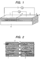
- Fig. 1 is a schematic view of an oxide superconductor wire material of the present invention.
- Fig. 2 is a schematic view of a joint part of the oxide superconductor wire material of the present invention.
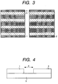
- Fig. 3 is a cross-sectional view of the oxide superconductor wire material of the present invention.
- Fig. 4 is a schematic view of the joint part of the oxide superconductor wire material of the present invention.
- Fig. 5 is a characteristic chart of the oxide superconductor wire material of the present invention.
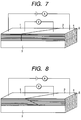
- Fig. 6 is a schematic view of the oxide superconductor wire material of the present invention.
- Fig. 7 is a schematic view of the oxide superconductor wire material of the present invention.
- Fig. 8 is a schematic view of the oxide superconductor wire material of the present invention.
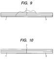
- Fig. 9 is a schematic view of a joint part of the oxide superconductor wire material of the present invention.
- Fig. 10 is a schematic view of a joint part of the oxide superconductor wire material of the present invention.
- Fig. 11 is a schematic view of a joint part of the oxide superconductor wire material of the present invention.
- Fig. 12 is a schematic view of a joint part of the oxide superconductor wire material of a comparative example of the present invention.
- Fig. 13 is a schematic view of a joint part of the oxide superconductor wire material of the comparative example of the present invention.
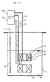
- Fig. 14 is a schematic view of the superconducting magnet system of the present invention.
- oxide superconductors Since the discovery of oxide superconductors, active research works have been carried out toward the preparation thereof into wire materials and the application thereof to power appliances. Compared with conventional superconductors, oxide superconductors characteristically have a far higher superconducting transition temperature (abbreviated as "Tc” hereinbelow) and a far higher upper critical magnetic field (abbreviated as “Hc 2 ,, hereinbelow), and therefore, the application of the superconductors has been expected in a variety of fields.
- Tc superconducting transition temperature
- Hc 2 upper critical magnetic field
- Bi superconductors have been known, including for example Bi 2 Sr 2 Ca 1 Cu 2 O x (abbreviated as "Bi-2212” hereinbelow) with Tc of about 85 K and (Bi, Pb) 2 Sr 2 Ca 2 Cu 3 O x (abbreviated as "Bi-2223” hereinbelow) with Tc of about 105 K.
- the application thereof as a conductor with a higher capacity to electric appliances is promising.
- the following methods have been employed. Firstly, powdery Bi-2212 is prepared preliminarily; then, the Bi-2212 is filled in a silver pipe, which is processed into a dense tape shape. Subsequently, subjecting the Bi-2212 to partial melt processing under heating while raising the temperature, a superior dense tape wire material in orientation is produced under annealing.
- Bi-2223 wire materials alternatively, the powder thereof is filled in a silver pipe and is then subjected to thermal treatment and processing in repetition, to produce a dense and oriented crystal matrix. Because the reaction to form a Bi-2223 phase generally proceeds as a solid reaction, in this case, the resulting crystal diameter is small compared with that of the Bi-2212 system, and additionally, the crystal includes a great number of anisotrophic phases. Consequently, the crystal matrix has a slightly lower critical current density (abbreviated as "Jc" hereinbelow), compared with those of the Bi-2212 wire materials .
- Jc critical current density
- the superconductive joint method of the present invention may be applicable widely to superconducting appliances, for example, superconducting transmission cable, bus bar, long conductor, permanent current switch device, large-scale magnet, nuclear magnetic resonance system, medicinal MRI system, superconducting power reserving system, magnetic separation unit, single-crystal drawing out system in magnetic field, freezer cooling superconducting magnet system and the like.
- the oxide superconductor is preferably of a series of Bi-2212; however, a wide variety of oxide superconductors may be usable, including for one example Bi-2223 or thallium superconductors, such as those superconductor materials described below;
- the tensile strength of the oxide superconductor wire material may be elevated approximately by 3 fold when the metal coating material is silver or gold or an alloy comprising one or two or more thereof as the mother material; or silver or gold alloy containing a trace amount of magnesium, titanium, nickel and copper as an additive, whereby the metal coating material can procure the function to increase the mechanical strength of the wire material.
- a method for manufacturing a superconducting magnet with the oxide superconductive joint comprising thermal treatment following the process of coil winding including the joint part, can practically produce a wire material capable of retaining superconducting profile over the long length with no local mechanical distortion, to achieve a permanent current magnet.
- the present inventors For the purpose of applying oxide superconductors to electric appliances, the present inventors have conventionally poured their energy mainly in improving the current passing properties of wire materials. Consequently, the inventors have developed a technique to provide a wire material with a critical current density as high as 1800 A/mm 2 in a 30-T outer magnetic field by using a Bi-2212 wire material with 19-55 cores. Even if attempts were made of jointing the wire material by conventionally known methods, however, a great number of problems occurred, with the decrease of the critical current density by one order or so at the joint part. Thus, no excellent properties of such wire material could be retained at the joint parts. Thus, the present inventors have continued investigations, to find a method for jointing a superconducting wire material to each other with no deterioration of the essential current passing properties of such high-performance multi-core tape wire material, as collectively shown herein.
- a multi-core oxide superconductor wire material is of a flat cross-sectional shape and is metal-coated; and in the joint structure, the C axis of the oxide superconductor crystal is substantially oriented in the longitudinal direction of the wire material; and the end face of the wire material in the longitudinal direction is in contact to each other at the joint part of the wire material and the C face of the oxide superconductor crystal is continuously oriented at the joint part of the wire material.
- the critical current density in the long multi-core oxide superconductor with such superconductive joint part was about 1000 A/mm 2 or more.
- the density will be increased possibly.
- the critical current confirmed was about 100 A or more at the current level and that most of the current was extremely high as much as 300 A or more.
- the present inventors have examined the macroscopic geometric structure of the joint part, and consequently, the inventors have found that good critical current properties can readily be realized when the wire material is of a tape shape and the end face of the tape is arranged vertical to the longitudinal direction if observed from the tape upper face.
- the inventors have found that by arranging the tape end face angular to the longitudinal direction if observed from the tape upper face in the superconductive joint part provided that the wire material is of a tape shape, the deterioration thereof against thermal distortion and mechanical distortion can be prevented, with the resultant marked effects on the life and reliability of the joint part.
- the inventors have found that the same effects may also be brought about when the wire material is of a tape shape and the tape end face is arranged angular to the longitudinal direction if observed from the tape side face in the superconductive joint structure or when the wire material is of a tape shape and the tape end face is arranged angular to the longitudinal direction if observed from the tape side face and tape upper face.
- the thickness of the elemental wire is about 0.1 mm or more to 0.3 mm or less.
- the thickness of the individual joint members agrees with the tape thickness used in the experiments, within the range experimentally verified by the present inventors. Therefore, it should be described additionally that experimental verification cannot be obtained outside the range, but the present invention is not limited to the range.
- the present inventors have found that the overall strength of the superconductive joint structure can be improved by defining the metal coating material of the wire material as silver or silver-gold alloy or an alloy produced by finely dispersing magnesium, nickel, aluminium or oxides of two or more thereof into silver or silver-gold alloy as the mother material.
- the oxide superconductor primarily may be of a Bi 2 Sr 2 Ca 2 Cu 1 O x phase.
- the present inventors have demonstrated additionally that by the method for jointing together the oxide superconductor tape, comprising a process of fabricating an oxide superconductor wire material, a process of arranging the end of the wire material in contact to each other, and a process of partially melting the wire material and the joint part, wherein a plurality of the superconductor filaments in crystal are put in contact to each other by thermal treatment, whereby the crystal is continuously jointed together in a superconducting manner, a metal-coated multi-core oxide superconductor wire material of a flat cross-sectional shape can be produced, wherein the C axis of the oxide superconductor crystal is substantially oriented in the longitudinal direction of the wire material; and the end face of the wire material in the longitudinal direction is in contact to each other at the joint part of the wire material and the C face of the oxide superconductor crystal is continuously oriented, at the joint part of the wire material.
- the individual tape wire materials are laminated together in a layer by using the tape faces, and the individual layers are jointed together to arrange the joint parts by utilizing the superconductive joint method in such a fashion that the joint parts might not overlap the positions of the joint parts of the upper and lower tape wire materials.
- the present inventors have found that when the partial melt temperatures of the sheath materials in a superconductive phase are different due to the difference in the sheath materials, as in one illustrative case when one coating material of a wire material composing a joint is silver and the other coating material of the wire material composing the joint is an alloy of silver-10 % gold, the melt temperature of the oxide superconductor coated with the silver-gold alloy can be reduced to about the same temperature of the silver coating materials through addition of silver at 0.01 % or more to 10 % or less, preferably 0.1 % or more to 1 % or less and most preferably 0.3 % to 0.7 % into the superconductor coated with the silver-gold alloy with a higher melt temperature, so that the influence of the difference (in melt temperature) can be reduced to a negligible level.
- the inventors have found that the superconductive jointing of the multi-core wire material with such different sheath materials can be realized, very effectively.
- a liquid phase is generated during partial melting. Because the liquid leaks from the joint part, however, the critical current density at the joint part may be lowered or short circuiting may occur between the adjacent tape wire materials wound around in a coil form, which eventually will reduce the intensity of a developed magnetic field. In accordance with the present invention, however, calcined bodies or the like won't be used as intervening substances at the joint part, so no leakage of the liquid phase should occur.
- the C face of the crystal grows from the ends of a pair of the butted multi-core wire materials, like a bridge over both sides of a river, to compose filaments of a continuous C phase.
- the superconductive joint method of the present invention may be applicable widely to superconducting appliances, for example, superconducting transmission cable, bus bar, long conductor, permanent current switch device, large-scale magnet, nuclear magnetic resonance system, medical MRI system, superconducting power reserving system, magnetic separation unit, single-crystal drawing out system in magnetic field, freezer cooling superconducting magnet system and the like, whereby the appliances can procure a higher efficiency and additionally, the loss of liquid helium can be reduced; the freezing potential for freezer cooling can be reduced; permanent current with a high-capacity and long-term stability can be realized if the method is applied to permanent current switch.
- superconducting appliances for example, superconducting transmission cable, bus bar, long conductor, permanent current switch device, large-scale magnet, nuclear magnetic resonance system, medical MRI system, superconducting power reserving system, magnetic separation unit, single-crystal drawing out system in magnetic field, freezer cooling superconducting magnet system and the like, whereby the appliances can procure a higher efficiency
- a powder was preliminarily synthesized and prepared to a final molar stoichiometric ratio of Bi, Sr, Ca and Cu of 2:2:1:2. It was confirmed by powder X-ray diffraction that an almost absolute single-phase was produced, and thereafter, filling the powder in a silver pipe to subject the powder to a process of preparing 19 and 55 multi-core wire materials, the resulting wire materials were molded in a tape shape.
- these multi-core tapes were cut into 40 to 100-mm pieces in the longitudinal direction. During cutting, additionally, special care was paid not to disorder the cross-sectional structure of the cut phase. It is important to thoroughly confirm whether the filaments of the multi-core wire materials are not damaged or the cut phase is flat. Samples with problems in these terms were subjected further to mechanical polishing or chemical polishing of the end parts, if necessary.
- the multi-core wire materials 1, 2 prepared as a pair were butted to each other at 6, by utilizing the upper face of tape 3 of the same material.
- silver was used in sheathing material 4, while 19 or 55-core superconductor filament 5 was used.
- the wire materials were partially melted and thermally processed within a temperature range of 860 °C to 900 °C in oxidizing atmosphere (for example, 880°C, for 15 minutes ,100% oxygen atmosphere), followed by annealing.
- the possible thermal conditions are 800°C to 900°C, for 5 minutes to for 60 minutes.
- the possible atmosphere conditions are 10 ⁇ 100% oxygen.
- the microfine structure of the joint part after such thermal treatment is shown schematically in Fig. 2.
- a joint structure with the cross- sectional shape as shown in Fig .2 is produced. If such jointing is realized, the critical current at the joint part in liquid helium is 450 A with a critical current density of 4500 A/mm 2 per cross section of the superconductor. Consequently, the critical current density at the joint part is almost the same as the density value of the superconducting wire material of itself.
- a wire material of a tape shape was prepared in the same manner as in Example 1. Subsequently, a joint part as schematically shown in Fig.4 was prepared and partially melted and thermally treated in the same manner. Joint distance "d” is provided between wire materials 1 and 2, and by using the "d” as a parameter, the relation between the critical current density and the "d” was examined. The results are shown in Fig.5. The figure indicates that the jointing distance "d" up to about 0.25 mm does not cause almost any reduction of the critical current density so good jointing can be maintained; and that a higher current density of 1000 A /mm 2 or more can be maintained although the current is slightly reduced at about 0.4 mm.
- the ends of the multi-core tape wire materials are butted to each other followed by partial melting and thermal treatment to effect jointing thereof.
- the distance between the butted parts should be approximately zero, but practically, the distance physically possible is under constraint, which involves a distance gap. It is indicated from the relation shown in Fig.5 that the gap is preferably within 0.4 mm, more preferably within 0.2 mm.
- Figs. 6, 7 and 8 depict examples of methods for preventing such deterioration of the properties.
- the jointing end face shown in Fig.1 is arranged angular to the wire material longitudinal direction, whereby stress concentration is reduced.
- Figs. 9 and 10 show one example of a plurality of tape wire materials in lamination. Both the figures depict the schematic view of the laminated tape at a state when observed from the side face.
- joint portions 7,7 are shifted between the upper and lower tapes.
- Fig.10 three such tapes are jointed together at the same position.
- the structure of Fig.10 is mechanically weak under the distortion along the wire material longitudinal direction, and when partially melted, the liquid components in the upper and lower tapes are mixed together to reduce the orientation at the joint part.
- alternate jointing of a plurality of tapes can reduce mechanical distortion and additionally can elevate the orientation of the crystal, with the resultant increase of Jc.
- Fig.11 depicts one example of jointing a multi-core tape wire material with different sheath materials.
- the wire materials were prepared in the same manner as in Example 1.
- two types of the sheath materials for the superconductor were used; namely, silver for wire material 1 and silver-10 wt % gold alloy for wire material 2.
- Jointing with such metal sheaths of different metals is used for jointing, for example superconducting magnet with permanent current switch, superconducting transmission cable with superconducting current limiting unit, superconducting trance or superconducting current lead or the like.
- the sheath material in the alloy sheath has a larger electric resistance and a smaller electric conductivity, the material is more excellent for superconducting current limiting unit, superconducting trance, superconducting current lead, superconducting permanent current switch and the like than silver.
- the magnet operation of permanent current can be realized, which has never been attained in conventional oxide superconductors.
- Fig. 14 shows an outline composition of the superconducting magnet system of the present invention.
- a superconducting magnet 13 and a persistent current switching element 14 are dipped in liquid helium 12 contained in a cryostat 11.
- the superconducting magnet 13 and the persistent current switching element 14 are connected by a connection part made of a superconductive wire, the way of the connection being disclosed in this specification, and further the connection part and the source for coil excitation 15 provided outside of the cryostat 11 are connected via current leads 16 for a coil.
- heaters 20 and 21 for heating a persistent current switch connected to a source for heating 19 via current leads 17 and 18 for heaters, are provided.
- a liquid helium surface level detector 22 is provided in the cryostat 11.
- the content of gold is at about 10 % by weight, but gold may be used in a wide range of 1 % to 20 %.
- the silver-10 wt % gold alloy sheath tape is arranged as shown in the figure, which is then partially melted and thermally treated in the same manner as in Example 1.
- the oxide superconductor in the silver-10 wt % gold alloy sheath tape has a melting point higher by about 10 °C than that in the silver sheath. Due to the difference in melting temperature between the two sheaths, good jointing through partial melting can hardly be procured.
- a trace amount of silver powder should preferably be added to the Bi-2212 powder filled in the silver-10 wt % gold alloy sheath tape.
- the silver particle size is about 1 to 10 microns, and the particle may be added in the form of metal or silver oxide, satisfactorily.
- the particle should be added preferably at 0.01 % or more to 10 % or less by weight, more preferably 0.1 % or more to 1 % or less by weight, to the Bi-2212. If the silver is added at a too low level, the effect cannot be exhibited; if the silver is added at a too high level, the effect is exerted insufficiently, which adversely blocks the superconducting current pass disadvantageously.
- the optimum level of the silver to be added should be selected, depending on the sheath material; for silver-10 wt % gold alloy, for example, silver may preferably be added at about 0.5 %. At any variation of silver distribution, furthermore, the melt temperature readily changes. Therefore, the alloy should be mixed together sufficiently homogeneously (for example, by ball-mill).
- the metal coating material of the wire material use may be made of alloys produced by finely dispersing magnesium, nickel, aluminium or oxides of two or more thereof in silver or silver-gold alloy as the mother material.
- alloys produced by finely dispersing magnesium, nickel, aluminium or oxides of two or more thereof in silver or silver-gold alloy as the mother material.
- Figs. 12 and 13 show Comparative Example 1.
- silver sheath multi-core wire materials 1 and 2 are jointed together on silver sheath tape wire material 3 in a similar manner to that in Example 1, but filling material 9 is inserted between the wire materials 1 and 2.
- a Bi-2212 calcined powder of a stoichiometric composition was used in the wire materials 1, 2, 3 and the filling material 9.
- the interval between the wire materials 1 and 2 was 0.5 mm.
- Fig.13 schematically depicts the results of partially melting and thermally processing the sample. As apparently shown in the figure, dense filling material 10 was produced by melt solidification, but the orientation thereof was severely poor.
- the critical current of the sample was 60A; and the critical current density was 670 A/mm 2 .
- a high-capacity jointing of a multi-core wire material of an oxide superconductor material can be attained, which enables current pass at a critical current density of 1000 A/mm 2 or less and a critical current of 300 to 500 A. Additionally, the magnet operation of permanent current is realized, which has never been achieved by conventional oxide superconductors.
- the superconducting connection between a permanet current switch and superconducting coil can be achieved , So the magnet operation of permanent current is realized.
Landscapes
- Superconductors And Manufacturing Methods Therefor (AREA)
Abstract
Description
Claims (13)
- A metal-coated multi-core oxide superconductor wire material of a flat cross-sectional shape, wherein the C axis of the oxide superconductor crystal is substantially oriented in the longitudinal direction of the wire material (1,2), and the end face of the wire material (1,2) in the longitudinal direction is in contact to each other and the C face of the oxide superconductor crystal is continuously oriented, at the joint part (6) of the wire material (1, 2).
- A long multi-core superconducting wire material with a superconductive joint part, wherein the critical current density is 1000 A/mm2 or more and the critical current is 100A or more at the superconductive joint part (6).
- An oxide superconductor wire material according to claim 1 or 2, wherein the oxide superconductor wire material (1,2) is of a tape shape and the end face of the tape is vertical to the longitudinal direction if observed from the upper face of the tape.
- An oxide superconductor wire material according to claim 1 or 2, wherein the oxide superconductor wire material (1,2) is of a tape shape and the end face of the tape is angular to the longitudinal direction if observed from the upper face of the tape.
- An oxide superconductor wire material according to claim 1 or 2, wherein the oxide superconductor wire material (1,2) is a tape shape and the end face of the tape is angular to the longitudinal direction if observed from the side face of the tape.
- An oxide superconductor wire material according to claim 1 or 2, wherein the oxide superconductor wire material (1,2) is of a tape shape and the end face of the tape is angular to the longitudinal direction if observed from the side and upper faces of the tape.
- An oxide superconductor wire material according to claim 1 or 2, wherein the thickness of the element wire of the oxide superconductor wire material (1,2) is 0.1 mm to 0.3 mm.
- An oxide superconductor wire material according to claim 1 or 2, wherein the metal coating material (4) of the oxide superconductor wire material (1,2) is silver or silver-gold alloy or an alloy produced by finely dispersing magnesium, nickel, aluminium or oxides of two or more thereof in the mother material.
- An oxide superconductor wire material according to claim 1 or 2, wherein the oxide superconductor wire material (1,2) is of a Bi2Sr2Ca2Cu1Ox phase.
- A method for producing an oxide superconductor wire material, comprising a process of fabricating an oxide superconductor wire, a process of arranging the end of the wire material (1,2) in contact to each other, and a process of partially melting the wire material and the joint part (6), wherein a plurality of the superconductor filaments (5) in crystal are put in contact to each other by thermal treatment, whereby the crystal is continuously jointed together in a superconductive manner.
- A method for jointing together an oxide superconductor wire material of a cross-sectional structure comprising a bundle of a plurality of oxide superconductor tapes, wherein the individual tape wire materials (1,2) are laminated together in a layer by using the tape faces; the individual layers are jointed together; and the joint parts (7,7) are arranged so that the joint parts might not overlap the positions of the joint parts of the upper and lower tape wire materials (1, 2).
- A method for jointing an oxide superconductor wire material according to claim 11, wherein one coating material of the oxide superconductor wire material (1) is silver and the other coating material of the oxide superconductor wire material (2) is silver-gold alloy and wherein the melt temperatures of the different coating materials on the oxide superconductor wire material are made almost equal by adding 0.01 % to 10 % by weight of silver into at least the superconductor (2) coated with the silver-gold alloy.
- A superconducting magnet system comprising:a persistent current switching element (14) made of an oxide superconductor, a superconducting magnet (13) made of an oxide superconductor, and a connection part connecting said switching element (14) and said magnet (13), wherein said connection part comprises oxide superconductor wire material according to claim 1 or 2.
Applications Claiming Priority (3)
| Application Number | Priority Date | Filing Date | Title |
|---|---|---|---|
| JP22970096 | 1996-08-30 | ||
| JP22970096 | 1996-08-30 | ||
| JP229700/96 | 1996-08-30 |
Publications (2)
| Publication Number | Publication Date |
|---|---|
| EP0827217A2 true EP0827217A2 (en) | 1998-03-04 |
| EP0827217A3 EP0827217A3 (en) | 1999-12-08 |
Family
ID=16896337
Family Applications (1)
| Application Number | Title | Priority Date | Filing Date |
|---|---|---|---|
| EP97115103A Withdrawn EP0827217A3 (en) | 1996-08-30 | 1997-09-01 | Oxide superconductor wire material and method for jointing the same together |
Country Status (2)
| Country | Link |
|---|---|
| US (1) | US6133814A (en) |
| EP (1) | EP0827217A3 (en) |
Cited By (3)
| Publication number | Priority date | Publication date | Assignee | Title |
|---|---|---|---|---|
| EP2168179B1 (en) * | 2007-06-22 | 2014-08-13 | NKT Cables Ultera A/S | A superconducting element joint |
| EP2709224B1 (en) * | 2012-09-14 | 2018-01-17 | Nexans | Assembly for electrically connecting two superconductive conductors |
| CN107924744A (en) * | 2015-07-31 | 2018-04-17 | 麦格尼法恩有限公司 | Change the magnetized instrument and method of superconductor |
Families Citing this family (12)
| Publication number | Priority date | Publication date | Assignee | Title |
|---|---|---|---|---|
| DE10225531B4 (en) * | 2002-06-10 | 2005-05-12 | Bruker Biospin Gmbh | Superconducting high-field magnetic coil with superconducting transition points |
| US7365271B2 (en) * | 2003-12-31 | 2008-04-29 | Superpower, Inc. | Superconducting articles, and methods for forming and using same |
| WO2007001383A2 (en) * | 2004-09-22 | 2007-01-04 | Superpower, Inc. | Superconductor components |
| US7972744B2 (en) | 2004-09-28 | 2011-07-05 | GM Global Technology Operations LLC | Fuel cell assembly |
| JP2007221013A (en) * | 2006-02-20 | 2007-08-30 | Hitachi Ltd | Permanent current switch |
| US8304372B2 (en) | 2007-01-31 | 2012-11-06 | Council Of Scientific And Industrial Research | Process for joining oxide superconducting tubes with a superconducting joint |
| US8195260B2 (en) * | 2008-07-23 | 2012-06-05 | American Superconductor Corporation | Two-sided splice for high temperature superconductor laminated wires |
| US8812069B2 (en) * | 2009-01-29 | 2014-08-19 | Hyper Tech Research, Inc | Low loss joint for superconducting wire |
| WO2012176074A1 (en) | 2011-06-21 | 2012-12-27 | Council Of Scientific & Industrial Research | A process for joining of tubes of (bi,pb) -2223 oxide high temperature superconductors using modified superconducting paste |
| GB2498999A (en) * | 2012-02-02 | 2013-08-07 | Siemens Plc | Mechanical superconducting switch |
| DE102015219956A1 (en) | 2015-10-14 | 2017-04-20 | Bruker Hts Gmbh | Superconductor structure for connecting strip conductors, in particular with a wavy or serrated seam |
| SG10202112214RA (en) | 2018-10-15 | 2021-12-30 | Tokamak Energy Ltd | High temperature superconductor magnet |
Family Cites Families (5)
| Publication number | Priority date | Publication date | Assignee | Title |
|---|---|---|---|---|
| AU653983B2 (en) * | 1991-02-25 | 1994-10-20 | Sumitomo Electric Industries, Ltd. | Junction between wires employing oxide superconductors and joining method therefor |
| DE69313891T2 (en) * | 1992-02-20 | 1998-05-07 | Sumitomo Electric Industries | Process for connecting superconducting wires made of oxide high-temperature superconductors |
| DE69325995T2 (en) * | 1992-04-03 | 2000-04-20 | Nippon Steel Corp. | COMPOSITE PRODUCT SUPER-CONDUCTING OXIDE MATERIALS AND THEIR PRODUCTION |
| JPH0797277A (en) * | 1993-08-02 | 1995-04-11 | Kyocera Corp | Method for joining oxide superconductors |
| JPH09143000A (en) * | 1995-11-28 | 1997-06-03 | Kyocera Corp | Method for joining oxide superconductors |
-
1997
- 1997-08-29 US US08/921,366 patent/US6133814A/en not_active Expired - Fee Related
- 1997-09-01 EP EP97115103A patent/EP0827217A3/en not_active Withdrawn
Cited By (3)
| Publication number | Priority date | Publication date | Assignee | Title |
|---|---|---|---|---|
| EP2168179B1 (en) * | 2007-06-22 | 2014-08-13 | NKT Cables Ultera A/S | A superconducting element joint |
| EP2709224B1 (en) * | 2012-09-14 | 2018-01-17 | Nexans | Assembly for electrically connecting two superconductive conductors |
| CN107924744A (en) * | 2015-07-31 | 2018-04-17 | 麦格尼法恩有限公司 | Change the magnetized instrument and method of superconductor |
Also Published As
| Publication number | Publication date |
|---|---|
| US6133814A (en) | 2000-10-17 |
| EP0827217A3 (en) | 1999-12-08 |
Similar Documents
| Publication | Publication Date | Title |
|---|---|---|
| EP0827217A2 (en) | Oxide superconductor wire material and method for jointing the same together | |
| Iijima et al. | Nb3Al multifilamentary wires continuously fabricated by rapid-quenching | |
| US7138581B2 (en) | Low resistance conductor, processes of production thereof, and electrical members using same | |
| JP2672334B2 (en) | Superconductor manufacturing method | |
| CA2617210A1 (en) | Architecture for high temperature superconductor wire | |
| EP0634379B1 (en) | Joined product of of superconductive oxide materials and its manufacture | |
| US6949490B2 (en) | High-TC superconducting ceramic oxide products and macroscopic and microscopic methods of making the same | |
| US4861751A (en) | Production of high temperature superconducting materials | |
| JP4010404B2 (en) | Superconducting wire and its manufacturing method | |
| JP2002373534A (en) | Superconducting wire, method for producing the same, and superconducting magnet using the same | |
| JP2636049B2 (en) | Method for producing oxide superconductor and method for producing oxide superconducting wire | |
| US5318948A (en) | Oxide superconductor, superconducting wire and coil using the same and method of production thereof | |
| US5882536A (en) | Method and etchant to join ag-clad BSSCO superconducting tape | |
| US6185810B1 (en) | Method of making high temperature superconducting ceramic oxide composite with reticulated metal foam | |
| JPH10188696A (en) | Oxide superconducting wire and joining method thereof | |
| Kosuge et al. | Incorporation of stabilizer to rapid-quenched and transformed Nb/sub 3/Al multifilamentary superconductors | |
| JP3161938B2 (en) | Superconducting wire manufacturing method | |
| JPH0917249A (en) | Oxide superconducting wire and method for producing the same | |
| JPH0982446A (en) | Superconductive connecting method for superconductive wire | |
| JP4925639B2 (en) | RE123 oxide superconductor and manufacturing method thereof | |
| US5583094A (en) | "Method for preparing hollow oxide superconductors" | |
| Sato | PROCESSING FOR HIGH-/C Bi-Sr-Ca-Cu-O WIRES | |
| Tachikawa | Recent progress in superconductors in Japan | |
| KR20030012273A (en) | Fabrication method of MgB2 superconducting wire | |
| EP0698930A1 (en) | Oxide superconductor and fabrication method of the same |
Legal Events
| Date | Code | Title | Description |
|---|---|---|---|
| PUAI | Public reference made under article 153(3) epc to a published international application that has entered the european phase |
Free format text: ORIGINAL CODE: 0009012 |
|
| AK | Designated contracting states |
Kind code of ref document: A2 Designated state(s): CH DE FR GB LI |
|
| PUAL | Search report despatched |
Free format text: ORIGINAL CODE: 0009013 |
|
| AK | Designated contracting states |
Kind code of ref document: A3 Designated state(s): AT BE CH DE DK ES FI FR GB GR IE IT LI LU MC NL PT SE |
|
| 17P | Request for examination filed |
Effective date: 20000412 |
|
| AKX | Designation fees paid |
Free format text: CH DE FR GB LI |
|
| 17Q | First examination report despatched |
Effective date: 20030425 |
|
| STAA | Information on the status of an ep patent application or granted ep patent |
Free format text: STATUS: THE APPLICATION IS DEEMED TO BE WITHDRAWN |
|
| 18D | Application deemed to be withdrawn |
Effective date: 20030906 |