EP2168179B1 - A superconducting element joint - Google Patents
A superconducting element joint Download PDFInfo
- Publication number
- EP2168179B1 EP2168179B1 EP08758244.1A EP08758244A EP2168179B1 EP 2168179 B1 EP2168179 B1 EP 2168179B1 EP 08758244 A EP08758244 A EP 08758244A EP 2168179 B1 EP2168179 B1 EP 2168179B1
- Authority
- EP
- European Patent Office
- Prior art keywords
- joint
- superconducting
- cable
- superconducting element
- joints
- Prior art date
- Legal status (The legal status is an assumption and is not a legal conclusion. Google has not performed a legal analysis and makes no representation as to the accuracy of the status listed.)
- Active
Links
Images


Classifications
-
- H—ELECTRICITY
- H01—ELECTRIC ELEMENTS
- H01R—ELECTRICALLY-CONDUCTIVE CONNECTIONS; STRUCTURAL ASSOCIATIONS OF A PLURALITY OF MUTUALLY-INSULATED ELECTRICAL CONNECTING ELEMENTS; COUPLING DEVICES; CURRENT COLLECTORS
- H01R4/00—Electrically-conductive connections between two or more conductive members in direct contact, i.e. touching one another; Means for effecting or maintaining such contact; Electrically-conductive connections having two or more spaced connecting locations for conductors and using contact members penetrating insulation
- H01R4/58—Electrically-conductive connections between two or more conductive members in direct contact, i.e. touching one another; Means for effecting or maintaining such contact; Electrically-conductive connections having two or more spaced connecting locations for conductors and using contact members penetrating insulation characterised by the form or material of the contacting members
- H01R4/68—Connections to or between superconductive connectors
-
- H—ELECTRICITY
- H02—GENERATION; CONVERSION OR DISTRIBUTION OF ELECTRIC POWER
- H02G—INSTALLATION OF ELECTRIC CABLES OR LINES, OR OF COMBINED OPTICAL AND ELECTRIC CABLES OR LINES
- H02G15/00—Cable fittings
- H02G15/34—Cable fittings for cryogenic cables
-
- H—ELECTRICITY
- H10—SEMICONDUCTOR DEVICES; ELECTRIC SOLID-STATE DEVICES NOT OTHERWISE PROVIDED FOR
- H10N—ELECTRIC SOLID-STATE DEVICES NOT OTHERWISE PROVIDED FOR
- H10N60/00—Superconducting devices
- H10N60/80—Constructional details
-
- H—ELECTRICITY
- H01—ELECTRIC ELEMENTS
- H01L—SEMICONDUCTOR DEVICES NOT COVERED BY CLASS H10
- H01L2924/00—Indexing scheme for arrangements or methods for connecting or disconnecting semiconductor or solid-state bodies as covered by H01L24/00
- H01L2924/0001—Technical content checked by a classifier
- H01L2924/0002—Not covered by any one of groups H01L24/00, H01L24/00 and H01L2224/00
-
- Y—GENERAL TAGGING OF NEW TECHNOLOGICAL DEVELOPMENTS; GENERAL TAGGING OF CROSS-SECTIONAL TECHNOLOGIES SPANNING OVER SEVERAL SECTIONS OF THE IPC; TECHNICAL SUBJECTS COVERED BY FORMER USPC CROSS-REFERENCE ART COLLECTIONS [XRACs] AND DIGESTS
- Y02—TECHNOLOGIES OR APPLICATIONS FOR MITIGATION OR ADAPTATION AGAINST CLIMATE CHANGE
- Y02E—REDUCTION OF GREENHOUSE GAS [GHG] EMISSIONS, RELATED TO ENERGY GENERATION, TRANSMISSION OR DISTRIBUTION
- Y02E40/00—Technologies for an efficient electrical power generation, transmission or distribution
- Y02E40/60—Superconducting electric elements or equipment; Power systems integrating superconducting elements or equipment
-
- Y—GENERAL TAGGING OF NEW TECHNOLOGICAL DEVELOPMENTS; GENERAL TAGGING OF CROSS-SECTIONAL TECHNOLOGIES SPANNING OVER SEVERAL SECTIONS OF THE IPC; TECHNICAL SUBJECTS COVERED BY FORMER USPC CROSS-REFERENCE ART COLLECTIONS [XRACs] AND DIGESTS
- Y10—TECHNICAL SUBJECTS COVERED BY FORMER USPC
- Y10T—TECHNICAL SUBJECTS COVERED BY FORMER US CLASSIFICATION
- Y10T29/00—Metal working
- Y10T29/49—Method of mechanical manufacture
- Y10T29/49002—Electrical device making
- Y10T29/49014—Superconductor
Definitions
- the invention relates to a superconducting element joint.
- Prior art superconducting element joints are usually provided by inserting an insert element with each end connecting each piece of superconducting cable to thereby form a double joint.
- Such superconducting element joints are e.g. known from US2005/0067184A1 .
- superconducting elements which are desired to joint.
- Such superconducting elements include superconducting busbars (in the following just called 'busbars'), superconducting cables, layers of superconducting cables and other similar elements.
- the superconducting cables known today includes in particular 3 major types, namely cold-dielectric co-axial design, warm-dielectric single-phase cables, and tri-axial cable design, i.e. three concentric phases centered around a carrier, former or similar and surrounded by a concentric electrical screen e.g. as described in WO06/111170 , US 6750399 and/or in EP1057193
- the tri-axial cable design has several advantages over other HTS cable designs.
- the advantages over a cold-dielectric co-axial design include:
- EP 0 827 217 describes that for joining together a metal-coated multi-core oxide superconductor wire material in a tape shape, the C axis of the oxide superconductor crystal is substantially orientated along the longitudinal direction of the wire material; the end face of the wire material is in contact to each other at the joint part; and the C phase of the oxide superconductor crystal is continuously oriented at the joint part.
- WO 2005/013450 describes a method for shielding the magnetic field generated by an electrical power transmission line, and an electrical power transmission line.
- the electrical power transmission line comprises at least one electrical cable and at least one shielding element made of ferromagnetic material arranged in a radially outer position with respect to the at least one cable.
- JP S 54152194 describes a three phased coaxial cable where two Y-shaped forked flexible plastic tubes each inserted among the insulating layers, one between an outer insulating layer, an outer conductor, and a middle insulator, and also between a middle conductor, and an inner insulating layer and covered.
- plug-in type of conductor splice which constitute an insert or transition piece, either in Cu, another low resistivity conductor or a composite insert made where the superconducting wires/tapes are embedded in a matrix.
- plug-in type insert reduces the complexity of the splice handling it introduces at least two conductor joints for each conductor and in the case of a Cu transition piece, it also introduces an extended ohmic transition.
- Another point that is not addressed in prior art is the undesired ac loss of the prior art conductor joint. Ohmic losses can be reduced by forced cooling.
- the ohmic joint losses accumulate and it will have to be reduced or removed by cooling together with other losses.
- the ohmic loss adds to the cryogenic losses as well as the magnetically generated ac losses of a superconducting ac cable.
- the contribution to the resulting loss is even more significant because no losses are generated in the superconductor.
- the invention relates to a superconducting element joint according to claim 1 which result in less Ohmic and/or cryogenic losses than the prior art plug-in type of conductor splice/joint described above.
- the superconducting element joint of the invention has very good properties with respect to mechanical strength, current rating, and fault current as well as high voltage capabilities.
- the description further refers to a process for providing a superconducting element joint which is relatively simple.
- the process for providing a superconducting element joint may preferably comprise a joining method that provides the level of technology that enables joining of HTS superconducting cables of different geometries, e.g. coax, triax, multi phase as well as DC cables.
- the solution provides a joint (the superconducting element joint) that is generally as strong as or stronger than the virgin cable with respect to mechanical strength. Also it has been found that the current related properties of the superconducting element joint is very good and that the current rating, and fault current as well as high voltage capabilities are substantial equal to or improved compared to these properties of the virgin cable. Furthermore the cable may be kept as slim as possible compared to the virgin cable.
- joint joint structure, element joint and splicing are used interchangeable to mean a connecting structure between two elements.
- the super conducting element joint may comprise one single joint or two or more joints, where juxtaposed elements of the superconducting element are preferably only involved in one joint structure.
- tape and wire are used interchangeable to mean any type of superconducting tape/wire (SC/HTS).
- wire means a superconducting wire having any cross-sectional shape such as round, oval, square, etc.
- a tape is a wire which is relatively flat i.e. having a cross-sectional shape with an aspect ratio of about 2 or more: 1.
- the term wire includes tapes.
- This invention offers a path to join cables as well as a stringent scheme of how to dimension the size of the HTS - HTS overlap (or HTS-HTS-HTS) in order to obtain a desired and or a predetermined dc and ac characteristic.
- the invention provides a superconducting element joint comprising a staggering arrangement, which is suggested in order to obtain an ultimate slim overall cable joint dimension as well as distributing the thermal load longitudinal from the ohmic dissipation however small this may be.
- the superconducting element joint is provided in the form of an all in one three-phase cable joint.
- SC means superconducting or superconductor.
- SC tape/wire is any superconducting wire in a broad sense, and includes also wires that also incorporate non-superconducting materials as a natural and integrated part of the wire such as but not limited materials such as the wire matrix, substrate, laminate, solder etc.
- HTS means high temperature SC tape/wires.
- SC-SC or a multiple SC-SC-SC- joint is understood to include any one or a multitude of joints that is formed by SC tape/wires including their partially non-superconducting components, even if the transition strictly speaking is not electrically superconducting.
- Virgin conductor means plain SC or normal tape/wire.
- Virgin cable means a cable without any joints.
- staggered joints means that the joints are at least partly dislocated with respect to each other in the longitudinal direction of the cable
- the superconducting element may be any kind of superconducting element preferably comprising at least one SC wire, such as superconducting cables, layers of superconducting cables, phases/neutral, conductors and other similar elements.
- phases' includes any non-neutral phases and any neutral phases unless other is mentioned.
- 'neutral' means a neutral phase.
- a neutral phase will have the same electrical potential as ground, and most often a neutral phase will be grounded.
- the superconducting joint of the invention comprises at least one direct SC-SC transition joint.
- a direct SC-SC transition joint also called a superconductor-superconductor joint is defined as being a joint comprising two end sections of superconducting elements joint together without an intermediate section of a non-superconducting conductor (normal conductor).
- a direct SC-SC includes joints where a minor normal conducting material occurs between the actual superconducting sections as long as the normal material is part of the joining means, e.g. solder, welding consumables, glue etc. or the material is an integrated part of the conductor to be joined, e.g. laminate, reinforcement, seals, coating etc.
- soldering material e.g.
- a direct SC-SC is characterized by being the opposite of a joint/connection where an intermediate section is used and where the intermediate section leads to at least two joints, one in each end of the intermediate section.
- the SC-SC transition joint may be between two identical superconducting elements or between two different superconducting elements, e.g. wire-wire, layer-layer, phase-phase, cable-cable, etc.
- the superconducting element joint comprises a direct SC-SC transition joint being provided between two joining ends and where one or both joining ends have at least one superconducting strand or superconducting layer.
- the superconducting elements comprising the at least one direct SC-SC transition joint may be any kind of superconducting elements, and they may be identical or they may differ from each other. In most situations the superconducting element joint will comprise a direct SC-SC transition joint between two superconducting elements having essentially identical cross sectional structure.
- At least one of the superconducting elements is a cable comprising at least 3 phases plus a neutral.
- the 3 phases being joined to another superconducting element with joints comprising or consisting essentially of direct SC-SC transition joints.
- the neutral may simply be grounded and need not being joint to another superconducting element.
- the superconducting elements comprise multi phase cables, such as 2, 3, 4 or 5 phase cables.
- At least one of the superconducting elements comprises a DC (Direct Current) cable, such as for example a superconducting element for a HVDC or high-voltage, direct current electric power transmission systems
- DC Direct Current
- At least one of the superconducting elements comprises an AC (Alternating Current) cable.
- At least one of the superconducting elements comprises a triax cable.
- a triax cable is a cable comprising 3 coaxial phases for example such as shown in Fig. 1 .
- Both of the superconducting elements are superconducting cables.
- One or more of the superconducting elements may comprise one or more non-superconducting materials.
- the non-superconducting material may for example be traditionally conductive material, such as metals e.g. Cu.
- the non-superconducting material may for example be wrapped totally or partly around one or more superconducting elements, e.g. for reducing risk of current leak or for reducing the risk of break down due to local heating.
- the direct SC-SC transition joint is a joint between two coaxial cables.
- the direct SC-SC transition joint is a joint between multi-phase cables of equal or different cross-sectional structure.
- the direct SC-SC transition joint is a joint between two DC cables of equal or different cross-sectional structure.
- cross-sectional structures of superconducting elements which may be joined in a direct SC-SC transition joints are the cross-sectional structures of the superconducting single phase or multi-phase cable described in any one of WO06/111170 , US 6750399 and/or in EP1057193 .
- the superconducting element joint has one or more superconductor-to-superconductor direct SC-SC transition joints (SC-SC joint) where it is understood that said SC-SC joint may include non superconducting material that in a natural way is an integrated part of said SC tape/wire, e.g. the tape/wire matrix, substrate, laminate as well as solder but not limited to these materials.
- SC-SC joint may include non superconducting material that in a natural way is an integrated part of said SC tape/wire, e.g. the tape/wire matrix, substrate, laminate as well as solder but not limited to these materials.
- the superconducting element joint is a joint between two superconducting cables of the type multi-phase cable where the phases as well as the neutral/screen is arranged concentrically around each other (e.g. a so-called triax cable or a coax cable) characterized by the cable ends being connected/joined with only one joint (in field joint as opposed to a prefabricated insert) and where said joint is obtained by a number of individual phase-joints (or neutral-joint) and where said phase-joint (or neutral-joint) is obtained by a number of layer-joints and where said superconducting layers or phases, in case both said individual phase layers or cable phases (or neutral) are superconducting, contains at least a direct SC-SC transition joint as defined above.
- all of the superconducting joints are direct SC-SC transition joints.
- the superconducting element joint comprises two or more phase/neutral joints
- these individual phase/neutral joints have spatial locations which are staggered with respect to every other phase/neutral joint in said superconducting element joint.
- the individual joint may be simpler to cool and the structure may be less bulky - the superconducting element joint of the final cable may even be as slim as the virgin cable.
- the superconducting element joint comprises joint of layers, such as layers of superconductive wires.
- the layers of superconductive wires may be joined in layer-by-layer-joints with corresponding layers of superconductive wires. These layer-by-layer-joints may preferably be direct SC-SC transition joints.
- the superconducting element joint comprises joint of layers where the joint of layers (layer-joints) are individually joint within each phase/neutral in said superconducting element joint.
- the layer-joints may be layer-by-layer joints the joints preferably being direct SC-SC transition joints.
- the layer-joints are staggered within each phase/neutral in said superconducting element joint.
- the superconducting elements comprise cables comprising dielectric between phases and between non-neutral-phase and neutral in said superconducting element joint wherein said dielectric between phases and between phase and neutral is similar to what it is in cable ends of said superconducting elements.
- the cables may be simple to join.
- the superconducting elements comprise at least one cable comprising dielectric wherein said dielectric is a wrap-on type dielectric or a solid dielectric, which can easily be removed totally or partly for providing the superconducting element joint.
- the dielectric may be any kind of dielectric which is useful in superconducting cables, such as the dielectrics which are described in prior art superconducting cable publications such as in any one of WO06/111170 , US 6750399 and/or in EP1057193 .
- the superconducting elements comprises at least one cable comprising dielectric wherein said dielectric is a compound dielectric characterized by a layered structure and impregnated with cooling fluid.
- said dielectric is a compound dielectric characterized by a layered structure and impregnated with cooling fluid.
- Such a material is e.g. described in applicants co-pending WO application PCT/DK2008/000208 .
- the superconducting elements comprise cables comprising dielectric wherein said dielectric is joint in a dielectric joint.
- the dielectric joint may preferably be dislocated in the longitudinal direction of the cable (staggered) with respect to said direct SC-SC transition joint(s).
- each of the superconducting elements comprises a former, said formers being joined in a former joint.
- the former joint preferably being a joint between former ends of the superconducting elements and the former joint preferably being a joint with an insert that ensures a smooth physical transition between the said cable ends either by prefabrication or is built up to present a smooth physical transition.
- the formers may in principle be joined by any methods, such as the methods which are described in prior art superconducting cable publications such as in any one of WO06/111170 , US 6750399 and/or in EP1057193 .
- the former joint comprises a former insert for said joint where the former insert is shaped/formed (dimension, hole size etc.) with the intend by means of forced flow to functioning as heat exchanger and thermal anchor/thermal arrestor for parts of or for the complete of said superconducting element joint.
- the former joint comprises a former insert characterized by an OD (radial dimension) that leads to a joint OD being the same as the superconducting elements, or a former insert that is narrower by a predefined amount in order to compensate for the thickness increase anticipated by the subsequent build of the joint.
- formers joint in said former joint is of a material preferably comprising at least one of stainless steel and fiber reinforced material.
- the formers may have shape and form for example they may - individually of each other - be shaped as a cylinder, a spiral, wound elements, interlocked elements and/or corrugated pipe.
- the formers and/or the former joint may-individually of each other - be fluid tight, semi-permeable or permeable to liquid e.g. to the cooling fluid.
- At least one of the formers is a stainless steel interlocked former similar to the one used for the triax and described in WO06/111170 .
- the superconducting element joint comprising one or more individual joints realized by any means such as by clamping, soldering, brazing, welding, gluing, etc.
- the superconducting element joint may comprise - e.g. in integrated form - any means of flow control, narrow section, forced flow heat exchanger, etc.
- any means of flow control, narrow section, forced flow heat exchanger, etc. The skilled person will know how to select and establish such means. Information for this may e.g. be found in any one of WO06/111170 , US 6750399 and/or in EP1057193 .
- the superconducting element joint comprises a flexible superconducting connection, e.g. superconducting foil/wrap (for example 100 mm wide YBCO) is used to connect two superconducting layers/phases to provide a direct SC-SC transition joint.
- a flexible superconducting connection e.g. superconducting foil/wrap (for example 100 mm wide YBCO) is used to connect two superconducting layers/phases to provide a direct SC-SC transition joint.
- the superconducting element joint may preferably comprise at least one diagnostic access, for providing a simple diagnosis of the conducting and/or temperature of the individually elements of the cable(s).
- the superconducting element joint comprises cooling feed/drain or regenerative access (for regenerative cooling means).
- the superconducting element joint comprises single phase access (e.g. for cable with one phase only or for cable with more than one phase).
- accesses may be provided by one access or by two or more accesses. It is generally known in the art to provide access to make diagnosis, cooling and similar and the skilled person may find further information in prior art superconducting cable publications such as in any one of WO06/111170 , US 6750399 and/or in EP1057193 .
- the superconducting element joint comprises a triax direct SC-SC transition joint.
- the superconducting element joint comprises a joint-sleeve or clamp wherein said joint-sleeve or clamp in part being a heat exchanger ensuring a thermal anchor or temperature arrestor, in part being a first means of an optional regenerative cooling access.
- the joint-sleeve or clamp may e.g. have a prefabricated or prepared interface to a cooling device.
- the superconducting element joint comprises a joint housing, which encloses said direct SC-SC transition joint.
- the joint housing may e.g. enclose the part of the superconducting elements comprising the superconducting element joint.
- the joint housing may e.g. facilitate diagnostics and/or regenerative cooling access/ports and/or other accesses to parts of the superconducting element joint.
- the one or more direct SC-SC transition joint is an all in one housing joint. This means that all the direct SC-SC transition joint(s) are enclosed in one house (joint housing).
- a house structure is formed in the length direction of the joined cables including the superconducting element joint joining the cable.
- the joint housing may or may not be closed.
- the joint housing may or may not comprise its own cooling medium supply/drain.
- the joint housing is open for flow of cooling medium along the superconducting element joint.
- the joint housing may e.g. comprise a prefabricated interface to a cooler.
- the prefabricated joint-cooler interface may be arranged such that the cooling being exchanged by means of a cooling fluid (gas, liquid, slush or mixture of these).
- the prefabricated joint-cooler interface is provided such that the cooling being exchanged by means of heat conduction through heat conducting material, typically metal the joint housing provides means electrically connecting a screen/shield to a cryostat and/or to the ground.
- the joint housing is thermally insulated preferably by at least one of vacuum, partly vacuum, partly foam, aerogel or similar nano-particle solid or liquid thermal insulation, fully foam insulated, aerogel or similar, Triax thermal insulation and mixtures thereof.
- the superconducting element joint is a cable joint, and the cable joint is slim/compact.
- the cable joint may e.g. have a cross-sectional area which is up to about 50 %, such as up to about 20 % such as up to about 5 % larger than the cross-sectional area of the virgin cable.
- the cable joint has a radial dimension (OD-outer dimension) which is essential as the parent cable to be joint (the virgin cable).
- said superconducting element joint is a cable joint that joins two cable end section of different dimensions.
- the superconducting element joint comprises one of or a combination of two or more of shim foils, wraps, thermal insulator or heat resistant foils with the purpose of protecting the underlying layers from the heat impact of the joining process, e.g. soldering, or strengthening the mechanical characteristics of the joint, or electrically strengthening the joint with a good conductor or a superconductor.
- the superconducting element joint consisting of SC-SC-SC transition joints where the SC-SC transition joint includes in a natural way any integrated parts of a superconducting tape/wire, i.e. including but not limited to, the non superconducting matrix, substrate, laminate, solder or other joining means.
- the superconducting element joint comprises a SC-normal metal-SC joint including at least one of shim foils, wraps, smoothening foils, mechanically reinforcing foils, superconducting foils, clamp shells and/or similar.
- the superconducting element joint comprises direct SC-SC transition joint of one or more phase conductors in a staggered fashion with respect to each other.
- the superconducting element joint comprises direct SC-SC transition joint of one or more conducting layers.
- the conducting layers are joints in a staggered fashion with respect to each other.
- the one or more conducting layers preferably being selected from SC (superconducting) conductors, normal (metal) conductors and other conductors such as polymer conductors, ceramic conductors and other.
- the superconducting elements comprises at least one cable comprising at least two dielectric layers, wherein said dielectric layers are joint in dielectric joints, said dielectric joint preferably being dislocated in the longitudinal direction of the cable (staggered) with respect to at least one superconducting element joint.
- the dielectric layers may be of materials as described above.
- the dielectric layers may be joined in dielectric joints as described above, said dielectric joint preferably being dislocated in the longitudinal direction of the cable (staggered) with respect to each other.
- the superconducting element joint comprises one or more conductor-conductor direct SC-SC transition joint where the minimum overlap between SC-SC or SC-SC-SC is sufficient to provide an ac power loss of the overlap region at rated/nominal load is substantial equal to or lower than the ac power loss of the virgin SC at the same load.
- the superconducting element joint comprises at least one direct SC-SC transition joint including a normal (non-superconducting) conductor where the minimum overlap between any number of normal conductors is sufficient to provide an ac power loss or a dc resistance of the overlap region at rated/nominal load which is substantial equal to or lower than the ac power loss or the dc resistance respectively of the virgin conductor at the same load.
- the superconducting element joint comprises at least one direct SC-SC transition joint including a normal (non-superconducting) conductor where the minimum overlap between any number of normal conductors and superconductors is sufficient to provide an ac power loss or a dc resistance of the overlap region at rated/nominal load which is substantial equal to or lower than the ac power loss or the dc resistance respectively of either of the virgin conductors at the same load.
- the superconducting element joint comprises a Cryoflex-Kapton field control.
- the superconducting element joint comprises insulating material (dielectric), preferably the same as in virgin cable (corresponding insulation in non-joint section of the cable).
- the superconducting element joint comprises insulating material different from in virgin cable. Thereby an increased or a decreased insulation effect in the superconducting element joint may be provided. In most situations it is desired that the insulating effect in the superconducting element joint is substantial equal to or higher than in the virgin superconducting elements which are joined.
- the superconducting element joint comprises an insulation which is 0%-100% in thickness or thicker compared to virgin cable, preferably the insulation is at least 1 %, such as at least 5 %, such as at least 50 % thicker than the thickness of the corresponding insulation in virgin cable (superconducting element(s)).
- the superconducting element joint comprises an insulation comprising other field controlling means.
- the superconducting element joint may be cooled using any cooling medium, such as the cooling medium described in prior art superconducting cable publications such as in any one of WO06/111170 , US 6750399 and/or in EP1057193 .
- the superconducting element joint is arranged to be cooled with liquid cryogen, e.g. forced flow/conduction cooled.
- the superconducting element joint is arranged to be cooled with gas.
- the superconducting element joint comprises one or more liquid cryogen feed and exhaust.
- the external of the superconducting element joint incorporates a heat exchanger (Cu clamp shell type).
- the superconducting element joint comprises an internal flow control, such as holes narrower former section or similar with the purpose to increase cooling interaction with the cooling cryogen.
- the superconducting element joint comprises a thermal anchor, such as a Cu clamp shell type forced flow cooling.
- the process for providing a superconducting element joint comprises providing at least one pair of superconducting elements and joining said pair of superconducting elements in a direct SC-SC transition joint.
- the process comprises use of one or more of shim foils, wraps, (thin) clamp shell or similar for protection of underlying electrical insulator, fixation of first superconducting (or normal conducting) layer, enabling or facilitating soldering or other connecting means, mechanically or electrically reinforcement or other facilitating purposes.
- the process comprises use of one or a combination of shim foils, wraps, thermal insulator or heat resistant foils with the purpose of protecting the underlying layers from the heat impact of the joining process, e.g. soldering, or strengthening the mechanical characteristics of the direct SC-SC transition joint, or electrically strengthening the direct SC-SC transition joint with a good conductor or a superconductor.
- the process comprises staggering build/positioning of single layers on the superconducting elements.
- the process comprises staggering build/positioning of each phase of the superconducting elements.
- the superconducting elements comprising one or more conductors in the form of tapes/wires
- the process comprising a procedure of tying down/fixating the conducting tapes/wires by wrapping around with a low pitch an "aid" tape/wire or by using braided hoses, e. g. Cu.
- the superconducting elements comprising one or more conductors (e.g. tapes/wires), the process comprising peel back insulation of 4 or more conductors together in one batch.
- conductors e.g. tapes/wires
- the superconducting elements comprising one or more conductors (e.g. tapes/wires), the process comprising a procedure of peeling back insulation from a bundle of conductors, the bundle containing at least 3 or more conductors.
- conductors e.g. tapes/wires
- the superconducting elements comprising one or more conductors in the form of tapes/wires
- the process comprising rewinding of a bundle of tapes/wires and the use or action of tying down the tapes/wires by temporarily winding tapes/wires around it to fixate the relevant HTS or Cu tapes/wires, i.e. a procedure of temporarily fixating tapes/wires.
- the superconducting elements comprising one or more conductors (e.g. tapes/wires), the process comprising peel back insulation from at least one conductor from a first superconducting element, joining the conductor with a conductor of a second superconducting element, cover the provided conductor direct SC-SC transition joint with the peeled back insulation by sliding it back, and joining said peeled back insulation to a corresponding insulation on said second superconducting element to thereby provide an insulation joint (dielectric joint), which is staggered with respect to said conductor direct SC-SC transition joint.
- the process comprising peel back insulation from at least one conductor from a first superconducting element, joining the conductor with a conductor of a second superconducting element, cover the provided conductor direct SC-SC transition joint with the peeled back insulation by sliding it back, and joining said peeled back insulation to a corresponding insulation on said second superconducting element to thereby provide an insulation joint (dielectric joint), which is staggered with respect to said
- the superconducting cable system comprises at least one joint in the form of a superconducting element joint as described above.
- the superconducting cable system also comprises a cooling system e.g. as described above and/or as described in prior art superconducting cable publications such as in any one of WO06/111170 , US 6750399 and/or in EP1057193 .
- the superconducting cable system also comprises a termination e.g. as described in prior art superconducting cable publications such as in any one of WO06/111170 , US 6750399 and/or in EP1057193 .
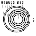
- FIG. 1 shows a cross-sectional cut of a tri-axial cable design.
- the triax comprises from inside out a cooling fluid 110, a former 111, a first phase 101, an insulation (dielectric) 105, a second phase 102, an insulation (dielectric) 105, a third phase 103, an insulation (dielectric) 105, a screen 104, a protection 106, a cooling fluid 110 and a thermal envelope 108.
- a cable having such structure is described in WO06/111170 .
- Such cable type may e.g. constitute one or both superconducting element in the superconducting element joint of the invention.
- FIG. 2 shows a cross-sectional cut of a part of a tri-axial cable design with a superconducting element joint according to the invention.
- 211 designates a former
- 205 designates insulation (dielectric)
- 206 designates a protection
- 201, 202 and 203 designate different phases (non-neutral)
- 204 designates a neutral phase (screen).
- 411J designates a former joint
- 201 J, 202J, 203J, and 204J designate SC-SC transition joints in the form of staggered joints between the individual phases may be a not shown dielectric.
- the dielectric may also be joined in the form of staggered joints e.g. dislocated with respect to other dielectric joints and/or dislocated with respect to one or more conductor joint.
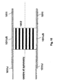
- FIG. 3 shows a cross-sectional cut of a part of another cable design with a superconducting element joint according to the invention.
- 305 designates insulation
- 302Cu designates a Cu conductor joint
- 302SC designates a superconductive conductor joint.
- FIG. 4 shows a cross-sectional cut of a part of another cable design with a superconducting element joint according to the invention.
- 411 designates a former
- 405 designates insulation
- 401 Cu designates a Cu conductor
- 401/401SC designates a superconductive conductor
- 411J designates a former joint.
- FIG. 5 shows a cross-sectional cut of a connecting between two SC wires in a SC-SC transition joint.
- 505 designates an insulator and 501 SC designates the two SC wires.
- FIG. 6 shows a cross-sectional cut of a connecting between two Cu wires.
- 605 designates an insulator and 601 C designates the two Cu wires.
- FIG. 7 shows a shim foil, which may be used in the invention as described above.
- FIG. 8 shows a cross-sectional cut of a connecting between two SC wires in a SC-SC transition joint provided by a superconducting wrap.
- 805 designates an insulator and 501 SC designates the two SC wires.
- 807 designates a shim foil, wrap or insert.
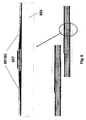
- FIG. 9 shows a cross-sectional cut of a cable with a former 911 comprising a welded joint 911J and a joint with a former insert 911JI.
- FIG. 10 shows a cross-sectional cut of a cable with a former 1011 comprising an overlapping joint 1011J and a solder/press joint 1011JS comprising an insert 1012.
Description
- The invention relates to a superconducting element joint.
- Prior art superconducting element joints are usually provided by inserting an insert element with each end connecting each piece of superconducting cable to thereby form a double joint.
- Such superconducting element joints are e.g. known from
US2005/0067184A1 . - In the prior art several types of superconducting elements which are desired to joint is known. Such superconducting elements include superconducting busbars (in the following just called 'busbars'), superconducting cables, layers of superconducting cables and other similar elements.
- For long length cable systems the technology of cable joining is necessary because the individually superconducting elements cannot be produced in sufficient length without joining/splicing elements.
- The superconducting cables known today includes in particular 3 major types, namely cold-dielectric co-axial design, warm-dielectric single-phase cables, and tri-axial cable design, i.e. three concentric phases centered around a carrier, former or similar and surrounded by a concentric electrical screen e.g. as described in
WO06/111170 US 6750399 and/or inEP1057193 - The tri-axial cable design has several advantages over other HTS cable designs. The advantages over a cold-dielectric co-axial design include:
- Reduced use of superconducting material (e.g. by 34-50 %) leading to reduced cost and reduced energy loss.
- Reduced use of cryogenic envelope materials and cold surface (e.g. by 30-50 %) leading to reduced cost and increased energy efficiency.
- Advantages of the tri-axial cable design compared to warm-dielectric single-phase cables include:
- Essentially no external magnetic fields creating disturbances externally to the cable.
- Improved relation between the electrical properties of inductance and capacitance leading to longer critical lengths, improved stability and reduced load-dependant voltage drops.
- Reduced magnetic fields internally in the cable leading to lower energy losses and improved performance of the superconducting materials.
- Reduced use of cryogenic envelope materials and cold surface (e.g. by a factor 30-50 %) leading to reduced cost and increased energy efficiency.
- Reduced number of cryogenic envelopes leading to fewer welding and fabrication steps, lower fabrication costs and increased reliability.
- Disadvantages of the tri-axial cable design compared to the two alternative designs may be the following:
- More complex cable design and termination design than the co-axial cold dielectric and the warm-dielectric single phase leading to higher risk in manufacturing and in utilization.
-
EP 0 827 217 describes that for joining together a metal-coated multi-core oxide superconductor wire material in a tape shape, the C axis of the oxide superconductor crystal is substantially orientated along the longitudinal direction of the wire material; the end face of the wire material is in contact to each other at the joint part; and the C phase of the oxide superconductor crystal is continuously oriented at the joint part. -
WO 2005/013450 describes a method for shielding the magnetic field generated by an electrical power transmission line, and an electrical power transmission line. The electrical power transmission line comprises at least one electrical cable and at least one shielding element made of ferromagnetic material arranged in a radially outer position with respect to the at least one cable. -
JP S 54152194 - As indicated above prior art as described in
US2005/0067184A1 has dealt with plug-in type of conductor splice, which constitute an insert or transition piece, either in Cu, another low resistivity conductor or a composite insert made where the superconducting wires/tapes are embedded in a matrix. Although using a plug-in type insert reduces the complexity of the splice handling it introduces at least two conductor joints for each conductor and in the case of a Cu transition piece, it also introduces an extended ohmic transition. Another point that is not addressed in prior art is the undesired ac loss of the prior art conductor joint. Ohmic losses can be reduced by forced cooling. However, for a long cable the ohmic joint losses accumulate and it will have to be reduced or removed by cooling together with other losses. In this case the ohmic loss adds to the cryogenic losses as well as the magnetically generated ac losses of a superconducting ac cable. For a dc cable the contribution to the resulting loss is even more significant because no losses are generated in the superconductor. - The invention relates to a superconducting element joint according to claim 1 which result in less Ohmic and/or cryogenic losses than the prior art plug-in type of conductor splice/joint described above. In particular the superconducting element joint of the invention has very good properties with respect to mechanical strength, current rating, and fault current as well as high voltage capabilities.
- The description further refers to a process for providing a superconducting element joint which is relatively simple. The process for providing a superconducting element joint may preferably comprise a joining method that provides the level of technology that enables joining of HTS superconducting cables of different geometries, e.g. coax, triax, multi phase as well as DC cables. The solution provides a joint (the superconducting element joint) that is generally as strong as or stronger than the virgin cable with respect to mechanical strength. Also it has been found that the current related properties of the superconducting element joint is very good and that the current rating, and fault current as well as high voltage capabilities are substantial equal to or improved compared to these properties of the virgin cable. Furthermore the cable may be kept as slim as possible compared to the virgin cable.
- The terms joint, joint structure, element joint and splicing are used interchangeable to mean a connecting structure between two elements. The super conducting element joint may comprise one single joint or two or more joints, where juxtaposed elements of the superconducting element are preferably only involved in one joint structure.
- The terms tape and wire are used interchangeable to mean any type of superconducting tape/wire (SC/HTS). The term wire means a superconducting wire having any cross-sectional shape such as round, oval, square, etc. A tape is a wire which is relatively flat i.e. having a cross-sectional shape with an aspect ratio of about 2 or more: 1. The term wire includes tapes.
- This invention offers a path to join cables as well as a stringent scheme of how to dimension the size of the HTS - HTS overlap (or HTS-HTS-HTS) in order to obtain a desired and or a predetermined dc and ac characteristic. The invention provides a superconducting element joint comprising a staggering arrangement, which is suggested in order to obtain an ultimate slim overall cable joint dimension as well as distributing the thermal load longitudinal from the ohmic dissipation however small this may be. In one embodiment the superconducting element joint is provided in the form of an all in one three-phase cable joint.
- SC means superconducting or superconductor.
- SC tape/wire is any superconducting wire in a broad sense, and includes also wires that also incorporate non-superconducting materials as a natural and integrated part of the wire such as but not limited materials such as the wire matrix, substrate, laminate, solder etc.
- HTS means high temperature SC tape/wires.
- SC-SC or a multiple SC-SC-SC- joint is understood to include any one or a multitude of joints that is formed by SC tape/wires including their partially non-superconducting components, even if the transition strictly speaking is not electrically superconducting.
- Virgin conductor means plain SC or normal tape/wire.
- Virgin cable means a cable without any joints.
- The term "staggered joints" means that the joints are at least partly dislocated with respect to each other in the longitudinal direction of the cable
- The superconducting element may be any kind of superconducting element preferably comprising at least one SC wire, such as superconducting cables, layers of superconducting cables, phases/neutral, conductors and other similar elements.
- The term 'phases' includes any non-neutral phases and any neutral phases unless other is mentioned. The term 'neutral' means a neutral phase.
- Generally a neutral phase will have the same electrical potential as ground, and most often a neutral phase will be grounded.
- The superconducting joint of the invention comprises at least one direct SC-SC transition joint. A direct SC-SC transition joint also called a superconductor-superconductor joint is defined as being a joint comprising two end sections of superconducting elements joint together without an intermediate section of a non-superconducting conductor (normal conductor). It is understood that a direct SC-SC includes joints where a minor normal conducting material occurs between the actual superconducting sections as long as the normal material is part of the joining means, e.g. solder, welding consumables, glue etc. or the material is an integrated part of the conductor to be joined, e.g. laminate, reinforcement, seals, coating etc. For example will HTS tapes/wires laminated with a soldering material (e.g. SS) and soldered together be regarded as a direct SC-SC joint in this context although there is no 100% superconducting connection between the actual superconducting parts theoretically. A direct SC-SC is characterized by being the opposite of a joint/connection where an intermediate section is used and where the intermediate section leads to at least two joints, one in each end of the intermediate section.
- The SC-SC transition joint may be between two identical superconducting elements or between two different superconducting elements, e.g. wire-wire, layer-layer, phase-phase, cable-cable, etc.
- According to an embodiment of the invention the superconducting element joint comprises a direct SC-SC transition joint being provided between two joining ends and where one or both joining ends have at least one superconducting strand or superconducting layer.
- The superconducting elements comprising the at least one direct SC-SC transition joint may be any kind of superconducting elements, and they may be identical or they may differ from each other. In most situations the superconducting element joint will comprise a direct SC-SC transition joint between two superconducting elements having essentially identical cross sectional structure.
- In one embodiment at least one of the superconducting elements is a cable comprising at least 3 phases plus a neutral. In this embodiment it may be desired that all of the phases including neutral being joint to another superconducting element with joints comprising or consisting essentially of direct SC-SC transition joints. In one embodiment the 3 phases being joined to another superconducting element with joints comprising or consisting essentially of direct SC-SC transition joints. The neutral may simply be grounded and need not being joint to another superconducting element.
- In one embodiment the superconducting elements comprise multi phase cables, such as 2, 3, 4 or 5 phase cables.
- In one example at least one of the superconducting elements comprises a DC (Direct Current) cable, such as for example a superconducting element for a HVDC or high-voltage, direct current electric power transmission systems
- In one example at least one of the superconducting elements comprises an AC (Alternating Current) cable.
- In one embodiment at least one of the superconducting elements comprises a triax cable. A triax cable is a cable comprising 3 coaxial phases for example such as shown in
Fig. 1 . - Both of the superconducting elements are superconducting cables.
- One or more of the superconducting elements may comprise one or more non-superconducting materials. The non-superconducting material may for example be traditionally conductive material, such as metals e.g. Cu. The non-superconducting material may for example be wrapped totally or partly around one or more superconducting elements, e.g. for reducing risk of current leak or for reducing the risk of break down due to local heating.
- The direct SC-SC transition joint is a joint between two coaxial cables.
- The direct SC-SC transition joint is a joint between multi-phase cables of equal or different cross-sectional structure.
- In one example the direct SC-SC transition joint is a joint between two DC cables of equal or different cross-sectional structure.
- Examples of cross-sectional structures of superconducting elements which may be joined in a direct SC-SC transition joints are the cross-sectional structures of the superconducting single phase or multi-phase cable described in any one of
WO06/111170 US 6750399 and/or inEP1057193 . - In one embodiment the superconducting element joint has one or more superconductor-to-superconductor direct SC-SC transition joints (SC-SC joint) where it is understood that said SC-SC joint may include non superconducting material that in a natural way is an integrated part of said SC tape/wire, e.g. the tape/wire matrix, substrate, laminate as well as solder but not limited to these materials.
- In one embodiment the superconducting element joint is a joint between two superconducting cables of the type multi-phase cable where the phases as well as the neutral/screen is arranged concentrically around each other (e.g. a so-called triax cable or a coax cable) characterized by the cable ends being connected/joined with only one joint (in field joint as opposed to a prefabricated insert) and where said joint is obtained by a number of individual phase-joints (or neutral-joint) and where said phase-joint (or neutral-joint) is obtained by a number of layer-joints and where said superconducting layers or phases, in case both said individual phase layers or cable phases (or neutral) are superconducting, contains at least a direct SC-SC transition joint as defined above. Preferably all of the superconducting joints are direct SC-SC transition joints.
- In one embodiment where the superconducting element joint comprises two or more phase/neutral joints, these individual phase/neutral joints have spatial locations which are staggered with respect to every other phase/neutral joint in said superconducting element joint. Thereby the individual joint may be simpler to cool and the structure may be less bulky - the superconducting element joint of the final cable may even be as slim as the virgin cable.
- In one embodiment the superconducting element joint comprises joint of layers, such as layers of superconductive wires. The layers of superconductive wires may be joined in layer-by-layer-joints with corresponding layers of superconductive wires. These layer-by-layer-joints may preferably be direct SC-SC transition joints. In one embodiment the superconducting element joint comprises joint of layers where the joint of layers (layer-joints) are individually joint within each phase/neutral in said superconducting element joint. The layer-joints may be layer-by-layer joints the joints preferably being direct SC-SC transition joints.
- In one embodiment the layer-joints are staggered within each phase/neutral in said superconducting element joint.
- In one embodiment the superconducting elements comprise cables comprising dielectric between phases and between non-neutral-phase and neutral in said superconducting element joint wherein said dielectric between phases and between phase and neutral is similar to what it is in cable ends of said superconducting elements. Thereby the cables may be simple to join.
- In one example the superconducting elements comprise at least one cable comprising dielectric wherein said dielectric is a wrap-on type dielectric or a solid dielectric, which can easily be removed totally or partly for providing the superconducting element joint.
- The dielectric may be any kind of dielectric which is useful in superconducting cables, such as the dielectrics which are described in prior art superconducting cable publications such as in any one of
WO06/111170 US 6750399 and/or inEP1057193 . - In one example the superconducting elements comprises at least one cable comprising dielectric wherein said dielectric is a compound dielectric characterized by a layered structure and impregnated with cooling fluid. Such a material is e.g. described in applicants co-pending WO application
PCT/DK2008/000208 - In one embodiment the superconducting elements comprise cables comprising dielectric wherein said dielectric is joint in a dielectric joint. The dielectric joint may preferably be dislocated in the longitudinal direction of the cable (staggered) with respect to said direct SC-SC transition joint(s).
- In one example each of the superconducting elements comprises a former, said formers being joined in a former joint. The former joint preferably being a joint between former ends of the superconducting elements and the former joint preferably being a joint with an insert that ensures a smooth physical transition between the said cable ends either by prefabrication or is built up to present a smooth physical transition.
- The formers may in principle be joined by any methods, such as the methods which are described in prior art superconducting cable publications such as in any one of
WO06/111170 US 6750399 and/or inEP1057193 . - In one example the former joint comprises a former insert for said joint where the former insert is shaped/formed (dimension, hole size etc.) with the intend by means of forced flow to functioning as heat exchanger and thermal anchor/thermal arrestor for parts of or for the complete of said superconducting element joint.
- In one example the former joint comprises a former insert characterized by an OD (radial dimension) that leads to a joint OD being the same as the superconducting elements, or a former insert that is narrower by a predefined amount in order to compensate for the thickness increase anticipated by the subsequent build of the joint.
- In one example formers joint in said former joint is of a material preferably comprising at least one of stainless steel and fiber reinforced material.
- The formers may have shape and form for example they may - individually of each other - be shaped as a cylinder, a spiral, wound elements, interlocked elements and/or corrugated pipe.
- The formers and/or the former joint may-individually of each other - be fluid tight, semi-permeable or permeable to liquid e.g. to the cooling fluid.
- In one example at least one of the formers is a stainless steel interlocked former similar to the one used for the triax and described in
WO06/111170 - In one example the superconducting element joint comprising one or more individual joints realized by any means such as by clamping, soldering, brazing, welding, gluing, etc.
- The superconducting element joint may comprise - e.g. in integrated form - any means of flow control, narrow section, forced flow heat exchanger, etc. The skilled person will know how to select and establish such means. Information for this may e.g. be found in any one of
WO06/111170 US 6750399 and/or inEP1057193 . - In one example the superconducting element joint comprises a flexible superconducting connection, e.g. superconducting foil/wrap (for example 100 mm wide YBCO) is used to connect two superconducting layers/phases to provide a direct SC-SC transition joint.
- The superconducting element joint may preferably comprise at least one diagnostic access, for providing a simple diagnosis of the conducting and/or temperature of the individually elements of the cable(s).
- In one example the superconducting element joint comprises cooling feed/drain or regenerative access (for regenerative cooling means).
- In one example the superconducting element joint comprises single phase access (e.g. for cable with one phase only or for cable with more than one phase).
- These accesses may be provided by one access or by two or more accesses. It is generally known in the art to provide access to make diagnosis, cooling and similar and the skilled person may find further information in prior art superconducting cable publications such as in any one of
WO06/111170 US 6750399 and/or inEP1057193 . - In one embodiment the superconducting element joint comprises a triax direct SC-SC transition joint.
- In one example the superconducting element joint comprises a joint-sleeve or clamp wherein said joint-sleeve or clamp in part being a heat exchanger ensuring a thermal anchor or temperature arrestor, in part being a first means of an optional regenerative cooling access. The joint-sleeve or clamp may e.g. have a prefabricated or prepared interface to a cooling device.
- In one embodiment the superconducting element joint comprises a joint housing, which encloses said direct SC-SC transition joint. The joint housing may e.g. enclose the part of the superconducting elements comprising the superconducting element joint. The joint housing may e.g. facilitate diagnostics and/or regenerative cooling access/ports and/or other accesses to parts of the superconducting element joint.
- In one embodiment the one or more direct SC-SC transition joint is an all in one housing joint. This means that all the direct SC-SC transition joint(s) are enclosed in one house (joint housing).
- By the term "enclosed in one house" is meant that a house structure is formed in the length direction of the joined cables including the superconducting element joint joining the cable. The joint housing may or may not be closed. The joint housing may or may not comprise its own cooling medium supply/drain. In one example the joint housing is open for flow of cooling medium along the superconducting element joint.
- The joint housing may e.g. comprise a prefabricated interface to a cooler. The prefabricated joint-cooler interface may be arranged such that the cooling being exchanged by means of a cooling fluid (gas, liquid, slush or mixture of these).
- In one example the prefabricated joint-cooler interface is provided such that the cooling being exchanged by means of heat conduction through heat conducting material, typically metal the joint housing provides means electrically connecting a screen/shield to a cryostat and/or to the ground.
- In one embodiment the joint housing is thermally insulated preferably by at least one of vacuum, partly vacuum, partly foam, aerogel or similar nano-particle solid or liquid thermal insulation, fully foam insulated, aerogel or similar, Triax thermal insulation and mixtures thereof.
- In one example the superconducting element joint is a cable joint, and the cable joint is slim/compact. The cable joint may e.g. have a cross-sectional area which is up to about 50 %, such as up to about 20 % such as up to about 5 % larger than the cross-sectional area of the virgin cable. In one example the cable joint has a radial dimension (OD-outer dimension) which is essential as the parent cable to be joint (the virgin cable).
- In one example said superconducting element joint is a cable joint that joins two cable end section of different dimensions.
- In one example the superconducting element joint comprises one of or a combination of two or more of shim foils, wraps, thermal insulator or heat resistant foils with the purpose of protecting the underlying layers from the heat impact of the joining process, e.g. soldering, or strengthening the mechanical characteristics of the joint, or electrically strengthening the joint with a good conductor or a superconductor.
- In one example the superconducting element joint consisting of SC-SC-SC transition joints where the SC-SC transition joint includes in a natural way any integrated parts of a superconducting tape/wire, i.e. including but not limited to, the non superconducting matrix, substrate, laminate, solder or other joining means.
- In one example the superconducting element joint comprises a SC-normal metal-SC joint including at least one of shim foils, wraps, smoothening foils, mechanically reinforcing foils, superconducting foils, clamp shells and/or similar.
- The superconducting element joint comprises direct SC-SC transition joint of one or more phase conductors in a staggered fashion with respect to each other.
- In one embodiment the superconducting element joint comprises direct SC-SC transition joint of one or more conducting layers. The conducting layers are joints in a staggered fashion with respect to each other. The one or more conducting layers preferably being selected from SC (superconducting) conductors, normal (metal) conductors and other conductors such as polymer conductors, ceramic conductors and other.
- In one embodiment the superconducting elements comprises at least one cable comprising at least two dielectric layers, wherein said dielectric layers are joint in dielectric joints, said dielectric joint preferably being dislocated in the longitudinal direction of the cable (staggered) with respect to at least one superconducting element joint. The dielectric layers may be of materials as described above. The dielectric layers may be joined in dielectric joints as described above, said dielectric joint preferably being dislocated in the longitudinal direction of the cable (staggered) with respect to each other.
- In one example the superconducting element joint comprises one or more conductor-conductor direct SC-SC transition joint where the minimum overlap between SC-SC or SC-SC-SC is sufficient to provide an ac power loss of the overlap region at rated/nominal load is substantial equal to or lower than the ac power loss of the virgin SC at the same load.
- In one example the superconducting element joint comprises at least one direct SC-SC transition joint including a normal (non-superconducting) conductor where the minimum overlap between any number of normal conductors is sufficient to provide an ac power loss or a dc resistance of the overlap region at rated/nominal load which is substantial equal to or lower than the ac power loss or the dc resistance respectively of the virgin conductor at the same load.
- In one example the superconducting element joint comprises at least one direct SC-SC transition joint including a normal (non-superconducting) conductor where the minimum overlap between any number of normal conductors and superconductors is sufficient to provide an ac power loss or a dc resistance of the overlap region at rated/nominal load which is substantial equal to or lower than the ac power loss or the dc resistance respectively of either of the virgin conductors at the same load.
- In one example the superconducting element joint comprises a Cryoflex-Kapton field control.
- In one embodiment the superconducting element joint comprises insulating material (dielectric), preferably the same as in virgin cable (corresponding insulation in non-joint section of the cable).
- In one example the superconducting element joint comprises insulating material different from in virgin cable. Thereby an increased or a decreased insulation effect in the superconducting element joint may be provided. In most situations it is desired that the insulating effect in the superconducting element joint is substantial equal to or higher than in the virgin superconducting elements which are joined.
- In one example the superconducting element joint comprises an insulation which is 0%-100% in thickness or thicker compared to virgin cable, preferably the insulation is at least 1 %, such as at least 5 %, such as at least 50 % thicker than the thickness of the corresponding insulation in virgin cable (superconducting element(s)).
- In one example the superconducting element joint comprises an insulation comprising other field controlling means.
- The superconducting element joint may be cooled using any cooling medium, such as the cooling medium described in prior art superconducting cable publications such as in any one of
WO06/111170 US 6750399 and/or inEP1057193 . - In one example the superconducting element joint is arranged to be cooled with liquid cryogen, e.g. forced flow/conduction cooled.
- In one example the superconducting element joint is arranged to be cooled with gas.
- In one example the superconducting element joint comprises one or more liquid cryogen feed and exhaust.
- In one example the external of the superconducting element joint incorporates a heat exchanger (Cu clamp shell type).
- In one example the superconducting element joint comprises an internal flow control, such as holes narrower former section or similar with the purpose to increase cooling interaction with the cooling cryogen.
- In one example the superconducting element joint comprises a thermal anchor, such as a Cu clamp shell type forced flow cooling.
- The process for providing a superconducting element joint comprises providing at least one pair of superconducting elements and joining said pair of superconducting elements in a direct SC-SC transition joint.
- In one example the process comprises use of one or more of shim foils, wraps, (thin) clamp shell or similar for protection of underlying electrical insulator, fixation of first superconducting (or normal conducting) layer, enabling or facilitating soldering or other connecting means, mechanically or electrically reinforcement or other facilitating purposes.
- In one example the process comprises use of one or a combination of shim foils, wraps, thermal insulator or heat resistant foils with the purpose of protecting the underlying layers from the heat impact of the joining process, e.g. soldering, or strengthening the mechanical characteristics of the direct SC-SC transition joint, or electrically strengthening the direct SC-SC transition joint with a good conductor or a superconductor.
- In one example the process comprises staggering build/positioning of single layers on the superconducting elements.
- In one example the process comprises staggering build/positioning of each phase of the superconducting elements.
- In one example of the process, the superconducting elements comprising one or more conductors in the form of tapes/wires, the process comprising a procedure of tying down/fixating the conducting tapes/wires by wrapping around with a low pitch an "aid" tape/wire or by using braided hoses, e. g. Cu.
- In one example of the process, the superconducting elements comprising one or more conductors (e.g. tapes/wires), the process comprising peel back insulation of 4 or more conductors together in one batch.
- In one example of the process, the superconducting elements comprising one or more conductors (e.g. tapes/wires), the process comprising a procedure of peeling back insulation from a bundle of conductors, the bundle containing at least 3 or more conductors.
- In one example of the process, the superconducting elements comprising one or more conductors in the form of tapes/wires, the process comprising rewinding of a bundle of tapes/wires and the use or action of tying down the tapes/wires by temporarily winding tapes/wires around it to fixate the relevant HTS or Cu tapes/wires, i.e. a procedure of temporarily fixating tapes/wires.
- In one example of the process, the superconducting elements comprising one or more conductors (e.g. tapes/wires), the process comprising peel back insulation from at least one conductor from a first superconducting element, joining the conductor with a conductor of a second superconducting element, cover the provided conductor direct SC-SC transition joint with the peeled back insulation by sliding it back, and joining said peeled back insulation to a corresponding insulation on said second superconducting element to thereby provide an insulation joint (dielectric joint), which is staggered with respect to said conductor direct SC-SC transition joint.
- Also described is a superconducting cable system comprising
- (1) a superconducting single phase or multi-phase cable, hereunder a triax cable,
- (2) at least one joint,
- (3) at least one termination,
- (4) the relevant cooling means.
- The superconducting cable system comprises at least one joint in the form of a superconducting element joint as described above.
- The superconducting cable system also comprises a cooling system e.g. as described above and/or as described in prior art superconducting cable publications such as in any one of
WO06/111170 US 6750399 and/or inEP1057193 . - The superconducting cable system also comprises a termination e.g. as described in prior art superconducting cable publications such as in any one of
WO06/111170 US 6750399 and/or inEP1057193 . - The invention will be explained more fully below in connection with a preferred embodiment and with reference to the drawings in which:
-
FIG. 1 shows a cross-sectional cut of a tri-axial cable design. -
FIG. 2 shows a cross-sectional cut of a part of a tri-axial cable design with a superconducting element joint according to the invention. -
FIG. 3 shows a cross-sectional cut of a part of another cable design with a superconducting element joint according to the invention. -
FIG. 4 shows a cross-sectional cut of a part of another cable design with a superconducting element joint according to the invention. -
FIG. 5 shows a cross-sectional cut of a connecting between two SC wires in a SC-SC transition joint. -
FIG. 6 shows a cross-sectional cut of a connecting between two Cu wires. -
FIG. 7 shows a shim foil. -
FIG. 8 shows a cross-sectional cut of a connecting between two SC wires in a SC-SC transition joint provided by a superconducting wrap. -
FIG. 9 shows a cross-sectional cut of a cable with a former. -
FIG. 10 shows a cross-sectional cut of a cable with a former. - The figures are schematic and simplified for clarity, and they just show details which are essential to the understanding of the invention, while other details are left out. Throughout, the same reference numerals are used for identical or corresponding parts.
- Some preferred embodiments have been shown in the foregoing, but it should be stressed that the invention is not limited to these, but may be embodied in other ways within the subject-matter defined in the following claims.
-
FIG. 1 shows a cross-sectional cut of a tri-axial cable design. The triax comprises from inside out a coolingfluid 110, a former 111, afirst phase 101, an insulation (dielectric) 105, asecond phase 102, an insulation (dielectric) 105, athird phase 103, an insulation (dielectric) 105, ascreen 104, aprotection 106, a coolingfluid 110 and athermal envelope 108. A cable having such structure is described inWO06/111170 -
FIG. 2 shows a cross-sectional cut of a part of a tri-axial cable design with a superconducting element joint according to the invention. 211 designates a former, 205 designates insulation (dielectric), 206 designates a protection, 201, 202 and 203 designate different phases (non-neutral) and 204 designates a neutral phase (screen). 411J designates a former joint, 201 J, 202J, 203J, and 204J designate SC-SC transition joints in the form of staggered joints Between the individual phases may be a not shown dielectric. The dielectric may also be joined in the form of staggered joints e.g. dislocated with respect to other dielectric joints and/or dislocated with respect to one or more conductor joint. -
FIG. 3 shows a cross-sectional cut of a part of another cable design with a superconducting element joint according to the invention. 305 designates insulation, 302Cu designates a Cu conductor joint, 302SC designates a superconductive conductor joint. -
FIG. 4 shows a cross-sectional cut of a part of another cable design with a superconducting element joint according to the invention. 411 designates a former, 405 designates insulation, 401 Cu designates a Cu conductor, 401/401SC designates a superconductive conductor. 411J designates a former joint. -
FIG. 5 shows a cross-sectional cut of a connecting between two SC wires in a SC-SC transition joint. 505 designates an insulator and 501 SC designates the two SC wires. -
FIG. 6 shows a cross-sectional cut of a connecting between two Cu wires. 605 designates an insulator and 601 C designates the two Cu wires. -
FIG. 7 shows a shim foil, which may be used in the invention as described above. -
FIG. 8 shows a cross-sectional cut of a connecting between two SC wires in a SC-SC transition joint provided by a superconducting wrap. 805 designates an insulator and 501 SC designates the two SC wires. 807 designates a shim foil, wrap or insert. -
FIG. 9 shows a cross-sectional cut of a cable with a former 911 comprising a welded joint 911J and a joint with a former insert 911JI. -
FIG. 10 shows a cross-sectional cut of a cable with a former 1011 comprising an overlapping joint 1011J and a solder/press joint 1011JS comprising aninsert 1012. - The figures are schematic and simplified for clarity, and they just show details which are essential to the understanding of the invention, while other details are left out. Throughout, the same reference numerals are used for identical or corresponding parts.
Claims (8)
- A superconducting element joint between two superconducting elements being multiphased coax or triax cables, where a triax cable is a cable comprising three coaxial phases, which superconducting element joint comprises a cable to cable joint, said superconducting elements each comprising a superconducting section, said superconducting element joint comprising at least two direct superconductor-superconductor joints (201J, 202J, 203J, 204J; 302SC; 401 SC),
where such direct superconductor-superconductor joint (201J, 202J, 203J, 204J; 302SC; 401 SC) is a joint structure comprising two end sections of said superconducting elements joined together where juxtaposed phases (101, 102, 103, 104; 201, 202, 203, 204) of the superconducting element are only involved in one joint structure without an intermediate section of a non-superconducting conductor, with the exception that non-superconducting material is part of the joining means between the superconducting section of one superconducting element and the superconducting section of the other superconducting element in said joint structure, the joining means being in the form of solder, welding consumable, or glue,
wherein each of said at least two direct superconductor-superconductor joints (201 J, 202J, 203J, 204J; 302SC; 401 SC) is a phase joint and has a spatial location, which is staggered with respect to the spatial location of every other phase joint (201J, 202J, 203J, 204J; 302SC; 401 SC) in said superconducting element joint where staggered joints means that the joints are at least partly dislocated with respect to each other in the longitudinal direction of the cable, and wherein all the phases are arranged concentrically around each other. - A superconducting element joint as claimed in claim 1, where said superconducting element joint is obtained by a number of individual phase joints and where said phase joint is obtained by a number of layer-joints.
- A superconducting element joint as claimed in claim 2, wherein said superconducting element joint comprises said layer-joints individually joint within each phase in said superconducting element joint, wherein said layer-joints are staggered within each phase in said superconducting element joint.
- A superconducting element joint as claimed in any one of the preceding claims wherein the superconducting elements comprise at least one cable comprising dielectric between phases in said superconducting element joint wherein said dielectric between phases is the same as the dielectric in cable ends of said superconducting elements.
- A superconducting element joint as claimed in any one of the preceding claims, wherein the superconducting elements comprises at least one cable comprising at least two dielectric layers, wherein said dielectric layers are joint in a dielectric joint, said dielectric joint being dislocated in the longitudinal direction of the cable, i.e. staggered, with respect to at least one phase joint (201 J, 202J, 203J, 204J; 302SC; 401 SC) and/or with respect to each other.
- A superconducting element joint as claimed in any one of the preceding claims, wherein said superconducting element joint comprises a joint housing, which encloses said superconducting elements.
- A superconducting element joint as claimed in claim 6, wherein said joint housing is thermally insulated by at least one of: vacuum, partly vacuum, partly foam, aerogel, or nano-particle solid or liquid thermal insulation, or fully foam insulated.
- A superconducting element joint as claimed in claim 6 or 7, where the joint housing comprises its own cooling medium supply/drain.
Applications Claiming Priority (3)
| Application Number | Priority Date | Filing Date | Title |
|---|---|---|---|
| US92934007P | 2007-06-22 | 2007-06-22 | |
| US95325607P | 2007-08-01 | 2007-08-01 | |
| PCT/DK2008/000235 WO2009000269A2 (en) | 2007-06-22 | 2008-06-23 | A superconducting element joint, a process for providing a superconducting element joint and a superconducting cable system |
Publications (2)
| Publication Number | Publication Date |
|---|---|
| EP2168179A2 EP2168179A2 (en) | 2010-03-31 |
| EP2168179B1 true EP2168179B1 (en) | 2014-08-13 |
Family
ID=39731659
Family Applications (1)
| Application Number | Title | Priority Date | Filing Date |
|---|---|---|---|
| EP08758244.1A Active EP2168179B1 (en) | 2007-06-22 | 2008-06-23 | A superconducting element joint |
Country Status (4)
| Country | Link |
|---|---|
| US (1) | US8463341B2 (en) |
| EP (1) | EP2168179B1 (en) |
| CN (1) | CN101785123B (en) |
| WO (1) | WO2009000269A2 (en) |
Families Citing this family (18)
| Publication number | Priority date | Publication date | Assignee | Title |
|---|---|---|---|---|
| CN101785123B (en) * | 2007-06-22 | 2013-01-30 | Nkt电缆乌尔特拉有限公司 | Superconducting element joint, method for providing a superconducting element joint |
| US8594756B2 (en) * | 2007-06-22 | 2013-11-26 | Nkt Cables Ultera A/S | Superconducting element joint, a process for providing a superconducting element joint and a superconducting cable system |
| US8716188B2 (en) * | 2010-09-15 | 2014-05-06 | Superpower, Inc. | Structure to reduce electroplated stabilizer content |
| KR101798659B1 (en) * | 2011-04-27 | 2017-11-16 | 엘에스전선 주식회사 | Super-conducting cable device |
| CN102545725B (en) * | 2012-02-02 | 2014-04-30 | 中国科学院电工研究所 | Super-conduction magnetic levitation device without liquid helium volatilization |
| CN103688317B (en) * | 2012-05-02 | 2016-09-28 | 古河电气工业株式会社 | Superconducting wire, the connecting structure of superconducting wire, the method for attachment of superconducting wire and the method for edge treatment of superconducting wire |
| KR101374177B1 (en) * | 2012-10-11 | 2014-03-14 | 케이조인스(주) | Methods of splicing 2g rebco high temperature superconductors using partial micro-melting diffusion pressurized splicing by direct face-to-face contact of high temperature superconducting layers and recovering superconductivity by oxygenation annealing |
| FR3010847B1 (en) * | 2013-09-19 | 2017-12-29 | Nexans | JUNCTION OF SUPERCONDUCTING CABLES |
| CN104167487B (en) * | 2014-07-31 | 2017-01-25 | 上海超导科技股份有限公司 | Yttrium system superconducting strip with contact resistance evenly distributed and method and device for manufacturing yttrium system superconducting strip |
| US9875826B2 (en) * | 2014-11-14 | 2018-01-23 | Novum Industria Llc | Field makeable cryostat/current connections for an HTS tape power cable |
| US11289640B2 (en) | 2016-01-21 | 2022-03-29 | Brookhaven Technology Group, Inc. | Second generation superconducting filaments and cable |
| WO2018048979A1 (en) | 2016-09-07 | 2018-03-15 | Brookhaven Technology Group, Inc. | Reel-to-reel exfoliation and processing of second generation superconductors |
| CN106911014B (en) * | 2017-01-13 | 2019-01-04 | 中国科学院合肥物质科学研究院 | A kind of superconducting joint box using indium silk bridging method |
| US10141493B2 (en) * | 2017-04-11 | 2018-11-27 | Microsoft Technology Licensing, Llc | Thermal management for superconducting interconnects |
| EP3635754A4 (en) | 2017-06-09 | 2021-02-24 | Brookhaven Technology Group, Inc. | Flexible multi-filament high temperature superconducting cable |
| US11645493B2 (en) | 2018-05-04 | 2023-05-09 | Microsoft Technology Licensing, Llc | Flow for quantized neural networks |
| US10453592B1 (en) | 2018-05-07 | 2019-10-22 | Microsoft Technology Licensing Llc | Reducing losses in superconducting cables |
| US11763157B2 (en) | 2019-11-03 | 2023-09-19 | Microsoft Technology Licensing, Llc | Protecting deep learned models |
Citations (7)
| Publication number | Priority date | Publication date | Assignee | Title |
|---|---|---|---|---|
| GB1306238A (en) * | 1969-08-01 | 1973-02-07 | ||
| JPS54152194A (en) * | 1978-05-16 | 1979-11-30 | Hitachi Cable Ltd | End treatment for three-phase coaxial cable |
| EP0827217A2 (en) * | 1996-08-30 | 1998-03-04 | Hitachi, Ltd. | Oxide superconductor wire material and method for jointing the same together |
| US20050016759A1 (en) * | 2003-07-21 | 2005-01-27 | Malozemoff Alexis P. | High temperature superconducting devices and related methods |
| WO2005013450A1 (en) * | 2003-07-30 | 2005-02-10 | Prysmian Cavi E Sistemi Energia S.R.L. | Method for shielding the magnetic field generated by an electrical power transmission line and electrical power transmission line so shielded |
| US20050067184A1 (en) * | 2003-09-29 | 2005-03-31 | Lg Cable Ltd., A Corporation Of Republic Of Korea | Jointing structure and jointing method for superconducting cable |
| WO2006111170A2 (en) * | 2005-04-21 | 2006-10-26 | Nkt Cables Ultera A/S | A superconductive multi-phase cable system, a method of its manufacture and its use |
Family Cites Families (14)
| Publication number | Priority date | Publication date | Assignee | Title |
|---|---|---|---|---|
| US3449818A (en) * | 1967-05-16 | 1969-06-17 | North American Rockwell | Superconductor joint |
| JPH01134881A (en) * | 1987-11-20 | 1989-05-26 | Toshiba Corp | Jointig method for superconducting conductor |
| JPH02186575A (en) * | 1989-01-12 | 1990-07-20 | Sanyo Electric Co Ltd | Junction of oxide superconductor |
| AU653983B2 (en) * | 1991-02-25 | 1994-10-20 | Sumitomo Electric Industries, Ltd. | Junction between wires employing oxide superconductors and joining method therefor |
| EP0545608A3 (en) * | 1991-12-02 | 1993-07-14 | General Electric Company | Superconducting joint for oxide superconductor tape |
| DE69313891T2 (en) * | 1992-02-20 | 1998-05-07 | Sumitomo Electric Industries | Process for connecting superconducting wires made of oxide high-temperature superconductors |
| JPH08138820A (en) * | 1994-11-02 | 1996-05-31 | Hitachi Ltd | Joining method of compound superconductive wire and conductor |
| JP3521612B2 (en) * | 1996-05-13 | 2004-04-19 | 住友電気工業株式会社 | Connection structure of superconducting conductor |
| DE19804342A1 (en) | 1998-02-05 | 1999-08-12 | Exner Hubertus | Method and device for distributing a bulk material flow over several partial flows |
| EP1163685A1 (en) * | 1999-02-19 | 2001-12-19 | Nkt Research Center A/S | A cable, a method of constructing a cable, and use of a cable |
| CN1179819C (en) * | 2001-11-07 | 2004-12-15 | 中国科学院电工研究所 | Welding method of high-temperature superconductive power cable joint and special apparatus thereof |
| DE102004007340B4 (en) * | 2004-02-16 | 2008-10-16 | Bruker Biospin Gmbh | Low drift superconducting high field magnet system and high resolution magnetic resonance spectrometer |
| WO2008148390A1 (en) | 2007-06-04 | 2008-12-11 | Nkt Cables Ultera A/S | A power cable comprising hts tape(s) |
| CN101785123B (en) * | 2007-06-22 | 2013-01-30 | Nkt电缆乌尔特拉有限公司 | Superconducting element joint, method for providing a superconducting element joint |
-
2008
- 2008-06-23 CN CN2008801036319A patent/CN101785123B/en active Active
- 2008-06-23 WO PCT/DK2008/000235 patent/WO2009000269A2/en active Application Filing
- 2008-06-23 US US12/665,095 patent/US8463341B2/en active Active
- 2008-06-23 EP EP08758244.1A patent/EP2168179B1/en active Active
Patent Citations (7)
| Publication number | Priority date | Publication date | Assignee | Title |
|---|---|---|---|---|
| GB1306238A (en) * | 1969-08-01 | 1973-02-07 | ||
| JPS54152194A (en) * | 1978-05-16 | 1979-11-30 | Hitachi Cable Ltd | End treatment for three-phase coaxial cable |
| EP0827217A2 (en) * | 1996-08-30 | 1998-03-04 | Hitachi, Ltd. | Oxide superconductor wire material and method for jointing the same together |
| US20050016759A1 (en) * | 2003-07-21 | 2005-01-27 | Malozemoff Alexis P. | High temperature superconducting devices and related methods |
| WO2005013450A1 (en) * | 2003-07-30 | 2005-02-10 | Prysmian Cavi E Sistemi Energia S.R.L. | Method for shielding the magnetic field generated by an electrical power transmission line and electrical power transmission line so shielded |
| US20050067184A1 (en) * | 2003-09-29 | 2005-03-31 | Lg Cable Ltd., A Corporation Of Republic Of Korea | Jointing structure and jointing method for superconducting cable |
| WO2006111170A2 (en) * | 2005-04-21 | 2006-10-26 | Nkt Cables Ultera A/S | A superconductive multi-phase cable system, a method of its manufacture and its use |
Also Published As
| Publication number | Publication date |
|---|---|
| US8463341B2 (en) | 2013-06-11 |
| WO2009000269A3 (en) | 2009-05-14 |
| CN101785123B (en) | 2013-01-30 |
| EP2168179A2 (en) | 2010-03-31 |
| CN101785123A (en) | 2010-07-21 |
| WO2009000269A2 (en) | 2008-12-31 |
| US20100184604A1 (en) | 2010-07-22 |
Similar Documents
| Publication | Publication Date | Title |
|---|---|---|
| EP2168179B1 (en) | A superconducting element joint | |
| US8594756B2 (en) | Superconducting element joint, a process for providing a superconducting element joint and a superconducting cable system | |
| US10943712B2 (en) | Superconducting cables and methods of making the same | |
| US8437819B2 (en) | Superconductor cable | |
| US7265297B2 (en) | Multiphase superconducting cable connection structure and multiphase superconducting cable line | |
| TW200532711A (en) | Terminals of multiphase superconducting cable | |
| JP4298450B2 (en) | Superconducting cable terminal structure | |
| EP1492200B1 (en) | Phase split structure of multiphase superconducting cable | |
| US6988915B2 (en) | Terminal structure of direct electric current multilayer structure superconducting cable and DC superconducting cable line | |
| JP6080168B2 (en) | Intermediate connection of superconducting cable | |
| CN110462756A (en) | Three-phase coaxial superconducting cable | |
| CN112435799A (en) | Three-phase coaxial superconducting cable current-carrying conductor cooling structure and superconducting cable current-carrying conductor | |
| KR102621367B1 (en) | Superconducting cable | |
| JP2000067663A (en) | Superconductive conductor | |
| JP2009070833A (en) | Manufacturing method of terminal structure of superconducting cable |
Legal Events
| Date | Code | Title | Description |
|---|---|---|---|
| PUAI | Public reference made under article 153(3) epc to a published international application that has entered the european phase |
Free format text: ORIGINAL CODE: 0009012 |
|
| 17P | Request for examination filed |
Effective date: 20100119 |
|
| AK | Designated contracting states |
Kind code of ref document: A2 Designated state(s): AT BE BG CH CY CZ DE DK EE ES FI FR GB GR HR HU IE IS IT LI LT LU LV MC MT NL NO PL PT RO SE SI SK TR |
|
| AX | Request for extension of the european patent |
Extension state: AL BA MK RS |
|
| RIN1 | Information on inventor provided before grant (corrected) |
Inventor name: RODEN, MARK Inventor name: TOLBERT, JERRY, C. Inventor name: TRAEHOLT, CHRESTEN Inventor name: NIELSEN, CARSTEN, THIDEMANN |
|
| 17Q | First examination report despatched |
Effective date: 20120521 |
|
| DAX | Request for extension of the european patent (deleted) | ||
| GRAP | Despatch of communication of intention to grant a patent |
Free format text: ORIGINAL CODE: EPIDOSNIGR1 |
|
| INTG | Intention to grant announced |
Effective date: 20140219 |
|
| GRAS | Grant fee paid |
Free format text: ORIGINAL CODE: EPIDOSNIGR3 |
|
| GRAA | (expected) grant |
Free format text: ORIGINAL CODE: 0009210 |
|
| AK | Designated contracting states |
Kind code of ref document: B1 Designated state(s): AT BE BG CH CY CZ DE DK EE ES FI FR GB GR HR HU IE IS IT LI LT LU LV MC MT NL NO PL PT RO SE SI SK TR |
|
| REG | Reference to a national code |
Ref country code: GB Ref legal event code: FG4D |
|
| REG | Reference to a national code |
Ref country code: CH Ref legal event code: EP Ref country code: AT Ref legal event code: REF Ref document number: 682663 Country of ref document: AT Kind code of ref document: T Effective date: 20140815 |
|
| REG | Reference to a national code |
Ref country code: IE Ref legal event code: FG4D |
|
| REG | Reference to a national code |
Ref country code: DE Ref legal event code: R096 Ref document number: 602008033836 Country of ref document: DE Effective date: 20140925 |
|
| REG | Reference to a national code |
Ref country code: NL Ref legal event code: VDEP Effective date: 20140813 |
|
| REG | Reference to a national code |
Ref country code: AT Ref legal event code: MK05 Ref document number: 682663 Country of ref document: AT Kind code of ref document: T Effective date: 20140813 |
|
| REG | Reference to a national code |
Ref country code: LT Ref legal event code: MG4D |
|
| PG25 | Lapsed in a contracting state [announced via postgrant information from national office to epo] |
Ref country code: FI Free format text: LAPSE BECAUSE OF FAILURE TO SUBMIT A TRANSLATION OF THE DESCRIPTION OR TO PAY THE FEE WITHIN THE PRESCRIBED TIME-LIMIT Effective date: 20140813 Ref country code: BG Free format text: LAPSE BECAUSE OF FAILURE TO SUBMIT A TRANSLATION OF THE DESCRIPTION OR TO PAY THE FEE WITHIN THE PRESCRIBED TIME-LIMIT Effective date: 20141113 Ref country code: ES Free format text: LAPSE BECAUSE OF FAILURE TO SUBMIT A TRANSLATION OF THE DESCRIPTION OR TO PAY THE FEE WITHIN THE PRESCRIBED TIME-LIMIT Effective date: 20140813 Ref country code: SE Free format text: LAPSE BECAUSE OF FAILURE TO SUBMIT A TRANSLATION OF THE DESCRIPTION OR TO PAY THE FEE WITHIN THE PRESCRIBED TIME-LIMIT Effective date: 20140813 Ref country code: LT Free format text: LAPSE BECAUSE OF FAILURE TO SUBMIT A TRANSLATION OF THE DESCRIPTION OR TO PAY THE FEE WITHIN THE PRESCRIBED TIME-LIMIT Effective date: 20140813 Ref country code: PT Free format text: LAPSE BECAUSE OF FAILURE TO SUBMIT A TRANSLATION OF THE DESCRIPTION OR TO PAY THE FEE WITHIN THE PRESCRIBED TIME-LIMIT Effective date: 20141215 Ref country code: GR Free format text: LAPSE BECAUSE OF FAILURE TO SUBMIT A TRANSLATION OF THE DESCRIPTION OR TO PAY THE FEE WITHIN THE PRESCRIBED TIME-LIMIT Effective date: 20141114 Ref country code: NO Free format text: LAPSE BECAUSE OF FAILURE TO SUBMIT A TRANSLATION OF THE DESCRIPTION OR TO PAY THE FEE WITHIN THE PRESCRIBED TIME-LIMIT Effective date: 20141113 |
|
| PG25 | Lapsed in a contracting state [announced via postgrant information from national office to epo] |
Ref country code: CY Free format text: LAPSE BECAUSE OF FAILURE TO SUBMIT A TRANSLATION OF THE DESCRIPTION OR TO PAY THE FEE WITHIN THE PRESCRIBED TIME-LIMIT Effective date: 20140813 Ref country code: IS Free format text: LAPSE BECAUSE OF FAILURE TO SUBMIT A TRANSLATION OF THE DESCRIPTION OR TO PAY THE FEE WITHIN THE PRESCRIBED TIME-LIMIT Effective date: 20141213 Ref country code: HR Free format text: LAPSE BECAUSE OF FAILURE TO SUBMIT A TRANSLATION OF THE DESCRIPTION OR TO PAY THE FEE WITHIN THE PRESCRIBED TIME-LIMIT Effective date: 20140813 Ref country code: AT Free format text: LAPSE BECAUSE OF FAILURE TO SUBMIT A TRANSLATION OF THE DESCRIPTION OR TO PAY THE FEE WITHIN THE PRESCRIBED TIME-LIMIT Effective date: 20140813 Ref country code: LV Free format text: LAPSE BECAUSE OF FAILURE TO SUBMIT A TRANSLATION OF THE DESCRIPTION OR TO PAY THE FEE WITHIN THE PRESCRIBED TIME-LIMIT Effective date: 20140813 |
|
| PG25 | Lapsed in a contracting state [announced via postgrant information from national office to epo] |
Ref country code: NL Free format text: LAPSE BECAUSE OF FAILURE TO SUBMIT A TRANSLATION OF THE DESCRIPTION OR TO PAY THE FEE WITHIN THE PRESCRIBED TIME-LIMIT Effective date: 20140813 |
|
| PG25 | Lapsed in a contracting state [announced via postgrant information from national office to epo] |
Ref country code: SK Free format text: LAPSE BECAUSE OF FAILURE TO SUBMIT A TRANSLATION OF THE DESCRIPTION OR TO PAY THE FEE WITHIN THE PRESCRIBED TIME-LIMIT Effective date: 20140813 Ref country code: CZ Free format text: LAPSE BECAUSE OF FAILURE TO SUBMIT A TRANSLATION OF THE DESCRIPTION OR TO PAY THE FEE WITHIN THE PRESCRIBED TIME-LIMIT Effective date: 20140813 Ref country code: RO Free format text: LAPSE BECAUSE OF FAILURE TO SUBMIT A TRANSLATION OF THE DESCRIPTION OR TO PAY THE FEE WITHIN THE PRESCRIBED TIME-LIMIT Effective date: 20140813 Ref country code: EE Free format text: LAPSE BECAUSE OF FAILURE TO SUBMIT A TRANSLATION OF THE DESCRIPTION OR TO PAY THE FEE WITHIN THE PRESCRIBED TIME-LIMIT Effective date: 20140813 Ref country code: DK Free format text: LAPSE BECAUSE OF FAILURE TO SUBMIT A TRANSLATION OF THE DESCRIPTION OR TO PAY THE FEE WITHIN THE PRESCRIBED TIME-LIMIT Effective date: 20140813 Ref country code: IT Free format text: LAPSE BECAUSE OF FAILURE TO SUBMIT A TRANSLATION OF THE DESCRIPTION OR TO PAY THE FEE WITHIN THE PRESCRIBED TIME-LIMIT Effective date: 20140813 |
|
| REG | Reference to a national code |
Ref country code: DE Ref legal event code: R097 Ref document number: 602008033836 Country of ref document: DE |
|
| PG25 | Lapsed in a contracting state [announced via postgrant information from national office to epo] |
Ref country code: PL Free format text: LAPSE BECAUSE OF FAILURE TO SUBMIT A TRANSLATION OF THE DESCRIPTION OR TO PAY THE FEE WITHIN THE PRESCRIBED TIME-LIMIT Effective date: 20140813 |
|
| PLBE | No opposition filed within time limit |
Free format text: ORIGINAL CODE: 0009261 |
|
| STAA | Information on the status of an ep patent application or granted ep patent |
Free format text: STATUS: NO OPPOSITION FILED WITHIN TIME LIMIT |
|
| 26N | No opposition filed |
Effective date: 20150515 |
|
| PG25 | Lapsed in a contracting state [announced via postgrant information from national office to epo] |
Ref country code: SI Free format text: LAPSE BECAUSE OF FAILURE TO SUBMIT A TRANSLATION OF THE DESCRIPTION OR TO PAY THE FEE WITHIN THE PRESCRIBED TIME-LIMIT Effective date: 20140813 |
|
| PG25 | Lapsed in a contracting state [announced via postgrant information from national office to epo] |
Ref country code: MC Free format text: LAPSE BECAUSE OF FAILURE TO SUBMIT A TRANSLATION OF THE DESCRIPTION OR TO PAY THE FEE WITHIN THE PRESCRIBED TIME-LIMIT Effective date: 20140813 |
|
| REG | Reference to a national code |
Ref country code: CH Ref legal event code: PL |
|
| PG25 | Lapsed in a contracting state [announced via postgrant information from national office to epo] |
Ref country code: LU Free format text: LAPSE BECAUSE OF FAILURE TO SUBMIT A TRANSLATION OF THE DESCRIPTION OR TO PAY THE FEE WITHIN THE PRESCRIBED TIME-LIMIT Effective date: 20150623 |
|
| REG | Reference to a national code |
Ref country code: IE Ref legal event code: MM4A |
|
| PG25 | Lapsed in a contracting state [announced via postgrant information from national office to epo] |
Ref country code: CH Free format text: LAPSE BECAUSE OF NON-PAYMENT OF DUE FEES Effective date: 20150630 Ref country code: IE Free format text: LAPSE BECAUSE OF NON-PAYMENT OF DUE FEES Effective date: 20150623 Ref country code: LI Free format text: LAPSE BECAUSE OF NON-PAYMENT OF DUE FEES Effective date: 20150630 |
|
| REG | Reference to a national code |
Ref country code: FR Ref legal event code: PLFP Year of fee payment: 9 |
|
| PG25 | Lapsed in a contracting state [announced via postgrant information from national office to epo] |
Ref country code: BE Free format text: LAPSE BECAUSE OF FAILURE TO SUBMIT A TRANSLATION OF THE DESCRIPTION OR TO PAY THE FEE WITHIN THE PRESCRIBED TIME-LIMIT Effective date: 20140813 |
|
| PG25 | Lapsed in a contracting state [announced via postgrant information from national office to epo] |
Ref country code: MT Free format text: LAPSE BECAUSE OF FAILURE TO SUBMIT A TRANSLATION OF THE DESCRIPTION OR TO PAY THE FEE WITHIN THE PRESCRIBED TIME-LIMIT Effective date: 20140813 |
|
| PG25 | Lapsed in a contracting state [announced via postgrant information from national office to epo] |
Ref country code: HU Free format text: LAPSE BECAUSE OF FAILURE TO SUBMIT A TRANSLATION OF THE DESCRIPTION OR TO PAY THE FEE WITHIN THE PRESCRIBED TIME-LIMIT; INVALID AB INITIO Effective date: 20080623 |
|
| REG | Reference to a national code |
Ref country code: FR Ref legal event code: PLFP Year of fee payment: 10 |
|
| PG25 | Lapsed in a contracting state [announced via postgrant information from national office to epo] |
Ref country code: TR Free format text: LAPSE BECAUSE OF FAILURE TO SUBMIT A TRANSLATION OF THE DESCRIPTION OR TO PAY THE FEE WITHIN THE PRESCRIBED TIME-LIMIT Effective date: 20140813 |
|
| REG | Reference to a national code |
Ref country code: FR Ref legal event code: PLFP Year of fee payment: 11 |
|
| REG | Reference to a national code |
Ref country code: DE Ref legal event code: R079 Ref document number: 602008033836 Country of ref document: DE Free format text: PREVIOUS MAIN CLASS: H01L0039020000 Ipc: H10N0060800000 |
|
| P01 | Opt-out of the competence of the unified patent court (upc) registered |
Effective date: 20230520 |
|
| PGFP | Annual fee paid to national office [announced via postgrant information from national office to epo] |
Ref country code: FR Payment date: 20230619 Year of fee payment: 16 Ref country code: DE Payment date: 20230621 Year of fee payment: 16 |
|
| PGFP | Annual fee paid to national office [announced via postgrant information from national office to epo] |
Ref country code: GB Payment date: 20230619 Year of fee payment: 16 |