EP0825740A2 - Circuit and method for controlling electric appliances - Google Patents
Circuit and method for controlling electric appliances Download PDFInfo
- Publication number
- EP0825740A2 EP0825740A2 EP97113682A EP97113682A EP0825740A2 EP 0825740 A2 EP0825740 A2 EP 0825740A2 EP 97113682 A EP97113682 A EP 97113682A EP 97113682 A EP97113682 A EP 97113682A EP 0825740 A2 EP0825740 A2 EP 0825740A2
- Authority
- EP
- European Patent Office
- Prior art keywords
- assigned
- circuit arrangement
- masks
- central computer
- program
- Prior art date
- Legal status (The legal status is an assumption and is not a legal conclusion. Google has not performed a legal analysis and makes no representation as to the accuracy of the status listed.)
- Granted
Links
Images

Classifications
-
- H—ELECTRICITY
- H04—ELECTRIC COMMUNICATION TECHNIQUE
- H04L—TRANSMISSION OF DIGITAL INFORMATION, e.g. TELEGRAPHIC COMMUNICATION
- H04L12/00—Data switching networks
- H04L12/28—Data switching networks characterised by path configuration, e.g. LAN [Local Area Networks] or WAN [Wide Area Networks]
- H04L12/2803—Home automation networks
- H04L12/2816—Controlling appliance services of a home automation network by calling their functionalities
- H04L12/282—Controlling appliance services of a home automation network by calling their functionalities based on user interaction within the home
-
- G—PHYSICS
- G05—CONTROLLING; REGULATING
- G05B—CONTROL OR REGULATING SYSTEMS IN GENERAL; FUNCTIONAL ELEMENTS OF SUCH SYSTEMS; MONITORING OR TESTING ARRANGEMENTS FOR SUCH SYSTEMS OR ELEMENTS
- G05B19/00—Programme-control systems
- G05B19/02—Programme-control systems electric
- G05B19/04—Programme control other than numerical control, i.e. in sequence controllers or logic controllers
- G05B19/042—Programme control other than numerical control, i.e. in sequence controllers or logic controllers using digital processors
-
- H—ELECTRICITY
- H04—ELECTRIC COMMUNICATION TECHNIQUE
- H04L—TRANSMISSION OF DIGITAL INFORMATION, e.g. TELEGRAPHIC COMMUNICATION
- H04L12/00—Data switching networks
- H04L12/28—Data switching networks characterised by path configuration, e.g. LAN [Local Area Networks] or WAN [Wide Area Networks]
- H04L12/2803—Home automation networks
Definitions
- the invention relates to a circuit arrangement and a method for control electrical household appliances according to the preamble of claim 1 or claim 15.
- a kitchen block with an electronic control device known.
- This kitchen block has a holder with grid-like holding elements, Power supply elements and control elements on which a plurality of kitchen modules can be detachably fastened in a grid-like manner, with the fastening on the holding device with an electronic control device and Energy supply device can be brought into operative connection.
- the electronic control device be considered as having the communication and control unit connected to the energy supply elements is formed which has a microprocessor with a memory arrangement which by means of a control panel is programmable.
- the control device is over a optoelectronic communication interface with an optical fiber data bus connected, which is in operative connection with the kitchen appliance modules.
- HES home electronic systems
- the invention is based on the object to specify a circuit arrangement and a method of the type mentioned at the outset, which make it easy to use.
- the circuit arrangement according to the invention enables the connection of different ones Household appliances and the connection of non-permanently installed devices (devices with plug connection), without the need to manually issue commands into the control system enter that initiate an activation or active integration of the devices in the system.
- the devices can be easily connected by a non-specialist and activate. Regardless of the respective state of expansion, the in the Figures shown operator guidance provided.
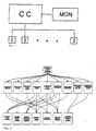
- the circuit arrangement according to the invention shown schematically in FIG. 1 serves for controlling an electrical household appliance 2 or a plurality of the same Household appliances or in particular household appliances with different functionality.
- household appliances are a washing machine, a dishwasher, a Air conditioning, a roller shutter drive system, lighting devices etc.
- the circuit arrangement comprises a central computer CC, which is a commercially available PC can be.
- the computer is connected to an optical display device MON.
- the household appliances 2 shown schematically in FIG. 1 are via the computer CC a control data line and possibly via a power supply line (Bus system) connected.
- a power supply line Bus system
- the circuit arrangement according to the invention When commissioning the circuit arrangement according to the invention or at a Connection of a domestic appliance 2 are the circuit arrangement according to the invention and parameterized the domestic appliance 2, the circuit arrangement according to the invention and the household appliance information (addresses and assignments) about the overall system, that can have interface circuits.
- the configuration of the household appliance installation is in a database system, not shown filed. This is e.g. during installation by an electrician built up. In addition to this data, manufacturers of home appliances Information about this is included, as will be described later.
- the circuit arrangement according to the invention enables the later integration of Household appliances without knowing what to do when commissioning Household appliances 2 can later be integrated into the system. Will household appliances become 2 connected, they behave like system components that are already in use Commissioning were integrated into the bus system. Connection of household appliances 2 and their logical integration can be done without a specialist.
- the circuit arrangement according to the invention for controlling electrical domestic appliances 2 thus has a central computer CC with an optical display device MON and 2 different functionality can be connected to the household appliances.
- the Central computer CC is assigned a control program that a first Has program part with which the transfer of data between central Computer CC and home appliances 2 is performed. State values belong to this data of home appliances and control commands that control home appliances will.
- the control program assigned to the central computer CC also has the first program part at least a second program part with which data are processed, based on which different functions by at least a home appliance can be realized.
- An example of such a function is Function "room temperature” by controlling a space heater and is realized by a blind drive unit.
- Another example is "Communication" function by a telephone, a fax machine or an answering machine can be realized.
- control program assigned to the central computer CC a third part of the program with which data is processed, on the Operator guidance is implemented.
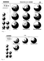
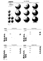
- control program assigned to the central computer CC is shown in FIG Designed so that masks can be displayed on the optical display device MON are the first and / or the second and / or the third part of the program assigned. Examples of such masks are shown in FIGS. 7 to 12.
- the optical display device MON is in particular a touch-sensitive Screen.
- the masks mentioned above have touch-sensitive controls on the touch of which specifiable input commands are generated.
- Examples of such control elements are the circular control elements in FIG. which are labeled “Security”, “Appointments”, “Communication”, “Devices”, etc. are; in Figure 8, which shows the screen mask when in that shown in Figure 7 Screen mask the "Devices" control element is operated, these are the control elements with "lighting / blinds", “heating / air conditioning”, “communication devices”, “Sockets” are referred to.
- the control program assigned to the central computer CC arranges the masks a hierarchy in such a way that the assigned to the third part of the program Masks the top hierarchical level is assigned, and that the first The lowest hierarchy level is assigned to masks assigned to the program part (e.g. "Overview mask” Single room temperature control "and function” Room temperature to adjust”).
- the masks have a hierarchy is assigned from at least three levels.
- a mask assigned to the third program section (“distributor mask”) points in each case at least one control element, the one assigned to the central computer CC Control program is designed in such a way that triggered by the Actuation of the control element another assigned to the third program part Mask or a mask assigned to the first and / or second program part the optical display device MON is shown.
- the distribution masks are one kind of jump distributor. Control elements are arranged on the mask work area, from which you can create further distribution masks or so-called work masks, i.e. Masks of a lower hierarchy level.
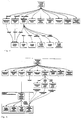
- At least two masks are assigned to the third program part, the control program assigned to the central computer CC at least two masks in two different hierarchy levels in the way assigned that a mask ("entry mask”, Figure 2 above) of an upper hierarchical level cannot be changed and that at least one additional mask (“distribution mask”) a lower hierarchical level depending on the respective configuration the system is changeable.
- the masks are one Hierarchy assigned in such a way that the assigned to the third part of the program Masks the highest hierarchical level is assigned during the first part of the program the lowest hierarchy level is assigned to assigned masks.
- the masks of the upper hierarchy levels shown on the optical display device MON Entry mask "Overview” and then triggered by a Actuation of the operating elements masks of further hierarchy levels (e.g. operating mask "Indoor climate” and application “Blinds / roller shutters").
- that assigned to the central computer CC Control program is designed in such a way that triggered by a the central computer CC supplied first information, the connection of a Home appliances referred to the circuit arrangement, and a second information that identifies the home appliance, updates the data of the first and second program parts will.
- the above are automatically Program parts changed.
- a personal computer to the circuit arrangement according to the invention or connected to the computer CC which has the function "communication” (when a modem is connected) as well Function “entertainment” (when equipped with computer games ", so after information identifying the connection of the personal computer to the computer CC has been supplied when operating the "Communication” or “Entertainment” in FIG.
- FIG. 2 branches to an operating mask, which are formed by operating elements e.g. controlling the personal computer or querying data enables that affect the personal computer.
- the possible branches are in Figures 5 and 6 shown. These figures show which hierarchical elements of the Control program or the screen masks by connecting another Home appliances are affected. While in the vertical structure shown in Figure 5 the control program or the mask hierarchy from the connection of another Home appliance or from the separation of a home appliance (3rd level) only hierarchy elements higher levels are affected, the effects are those in FIG. 6 hierarchy structure shown further, since hierarchy elements of the same Hierarchy level are affected.
- an intermediate level is created on the basis of the application information introduced in the operating structure so that all devices, possibly on Costs of an additional operating step remain operable.
- the required database entries are in a configuration database created by the installer linked database.
- control information of the applications is in so-called HCG files for each application added for computers.
- each application comes with a configuration program that specifies the application-specific Controls generated from the database, and the screen masks builds up.
- the software consists of a kernel, the kernel, and applications that are added later can be.
- the so-called first and second Information the data of the third part of the program are also updated.
- the Connecting a home appliance to the computer is the content of the above Program parts and thus also the assigned representable operating screens changed.
- the first information that the connection of a household appliance to the circuit arrangement is referred to in the circuit arrangement, for example via a keyboard can be entered. It can also be provided that this first information is provided by a Circuit element of the circuit arrangement is formed, which is the connection recognizes the home appliance to the circuit arrangement. The detection takes place in the Way that the circuit element when connecting a household appliance with its ground contact is connected so that the circuit element is supplied with the ground potential becomes.
- the invention also relates to a domestic appliance 2 connected to a circuit arrangement according to the invention or can be connected to a computer CC.
- a home appliance has in particular a memory in which one identifies the household appliance Information can be saved. This information is available at the time of connection or transferred to the computer when asked, which then updates the program parts or the corresponding screen masks.
- This information identifying a home appliance can be stored on a data carrier, e.g. one Magnetic stripes, chip etc. are stored, which is permanently arranged in the household appliance is or can be introduced into this.
- a data carrier e.g. one Magnetic stripes, chip etc. are stored, which is permanently arranged in the household appliance is or can be introduced into this.
- the invention also relates to a method for controlling electrical household appliances a circuit arrangement described above.
- data is transferred between the central computer CC and household appliances and Processed data based on which different functions by at least a home appliance can be realized.
- Data are also processed on whose Basis the operator guidance is realized.
Abstract
Description
Die Erfindung betrifft eine Schaltungsanordnung und ein Verfahren zur Steuerung
elektrischer Hausgeräte nach dem Oberbegriff des Anspruchs 1 bzw. nach Anspruch
15.The invention relates to a circuit arrangement and a method for control
electrical household appliances according to the preamble of
Aus der deutschen Patentanmeldung DE 44 46 962.4 ist eine Schaltungsanordnung zur Steuerung elektrischer Haushaltsgeräte bekannt, die untereinander, mit einem zentralen Rechner und/oder einer Anzeigeeinrichtung verbindbar sind, wobei den Haushaltsgeräten jeweils eine lokale Steuerung und jeweils ein Speicher zur Zwischenspeicherung von Daten zugeordnet sind. In der lokalen Steuerung eines Haushaltsgeräts ist dabei ein in der Weise ausgestaltetes Steuerungsprogramm zugeordnet, das aus Meß- und/oder Zustandsdaten des jeweiligen Haushaltsgeräts nach einer ersten Verarbeitungsvorschritt erste Zwischenwertdaten gebildet werden. In Abhängigkeit der ersten Zwischenwertdaten oder in Abhängigkeit extern gebildeter zweiter Zwischenwertdaten werden nach einer zweiten Verarbeitungsvorschrift Stellglieder des Haushaltsgeräts gesteuert.From the German patent application DE 44 46 962.4 is a circuit arrangement Known for controlling electrical household appliances that work with one another central computer and / or a display device can be connected, the Household appliances each have a local control and a memory for temporary storage of data are associated. In the local control of a household appliance a control program designed in this way is assigned, that from measurement and / or status data of the respective household appliance after a first intermediate processing step. Dependent on the first intermediate value data or, depending on the externally formed second Intermediate value data are actuators of the Home appliance controlled.
Aus der DE-OS 31 20 723 ist ein Küchenblock mit elektronischer Steuereinrichtung bekannt. Dieser Küchenblock weist eine Halterung mit rasterartig angeordneten Halteelementen, Energieversorgungselementen und Steuerungselementen auf, an der rasterartig eine Mehrzahl von Küchenmodulen lösbar befestigbar sind, die mit der Befestigung an der Halteeinrichtung mit einer elektronischen Steuereinrichtung und Energieversorgungseinrichtung in Wirkverbindung bringbar sind. In diesem Zusammenhang ist vorgeschlagen worden, daß die elektronische Steuereinrichtung als mit den Energieversorgungselementen verbundene Kommunikations- und Steuereinheit ausgebildet ist, die einen Mikroprozessor mit Speicheranordnung aufweist, der mittels eines Bedienfeldes programmierbar ist. Die Steuereinrichtung ist über ein optoelektronisches Kommunikations-Interface mit einem Lichtleiter-Datenbus verbunden, der mit den Küchengeräte-Modulen in Wirkverbindung steht.From DE-OS 31 20 723 is a kitchen block with an electronic control device known. This kitchen block has a holder with grid-like holding elements, Power supply elements and control elements on which a plurality of kitchen modules can be detachably fastened in a grid-like manner, with the fastening on the holding device with an electronic control device and Energy supply device can be brought into operative connection. In this context it has been proposed that the electronic control device be considered as having the communication and control unit connected to the energy supply elements is formed which has a microprocessor with a memory arrangement which by means of a control panel is programmable. The control device is over a optoelectronic communication interface with an optical fiber data bus connected, which is in operative connection with the kitchen appliance modules.
Derartige Steuerungssysteme zur Steuerung einer Mehrzahl von Geräten im häuslichen Bereich, sogenannte Home-Electronic-Systeme (HES), können bei komplexer Konfiguration Bedienprozeduren erfordern, die sich für die potentiellen Bedienpersonen als relativ schwierig erweisen können.Such control systems for controlling a plurality of devices in the home Area, so-called home electronic systems (HES), can be more complex Configuration operating procedures require that are appropriate for the potential operators can prove to be relatively difficult.
Ausgehend von diesem Stand der Technik liegt der Erfindung die Aufgabe zugrunde, eine Schaltungsanordnung und ein Verfahren der eingangs genannten Art anzugeben, welche eine einfache Bedienbarkeit ermöglichen.Starting from this prior art, the invention is based on the object to specify a circuit arrangement and a method of the type mentioned at the outset, which make it easy to use.
Die Lösung dieser Aufgabe erfolgt durch eine Schaltungsanordnung und ein Verfahren, die in den Ansprüchen definiert sind.This problem is solved by a circuit arrangement and a method, which are defined in the claims.
Die erfindungsgemäße Schaltungsanordnung ermöglicht den Anschluß unterschiedlicher Hausgeräte sowie den Anschluß nicht festinstallierter Geräte (Geräte mit Steckeranschluß), ohne daß es erforderlich ist, manuell Befehle in das Steuerungssystem einzugeben, die eine Aktivierung bzw. Wirkintegration der Geräte im System initiieren. Die Geräte lassen sich in einfacher Weise und durch einen Nichtfachmann anschließen und aktivieren. Unabhängig von dem jeweiligen Ausbauzustand wird die in den Figuren dargestellte Bedienerführung zur Verfügung gestellt.The circuit arrangement according to the invention enables the connection of different ones Household appliances and the connection of non-permanently installed devices (devices with plug connection), without the need to manually issue commands into the control system enter that initiate an activation or active integration of the devices in the system. The devices can be easily connected by a non-specialist and activate. Regardless of the respective state of expansion, the in the Figures shown operator guidance provided.
Die Erfindung wird nun anhand der Zeichnung beschrieben.The invention will now be described with reference to the drawing.
Es zeigen
- Fig. 1
- ein Blockschaltbild einer erfindungsgemäßen Schaltungsanordnung;
- Fig. 2 bis Fig. 6
- Strukturen von Bildschirmmasken, die durch eine Schaltungsanordnung
gemäß
Figur 1 mit einer optischen Anzeigeeinrichtung darstellbar sind, und Strukturen von Programmteilen des Steuerungsprogramm, das einem Rechner der Schaltungsanordnung zugeordnet ist; - Fig. 7 bis Fig. 12
- Beispiele für Bildschirmmasken, die insbesondere mit Bedienelementen
ausgestaltet sind, nach den
Figuren 2 bis 6.
- Fig. 1
- a block diagram of a circuit arrangement according to the invention;
- 2 to 6
- Structures of screen masks which can be represented by a circuit arrangement according to FIG. 1 with an optical display device, and structures of program parts of the control program which is assigned to a computer of the circuit arrangement;
- 7 to 12
- Examples of screen masks, which are designed in particular with operating elements, according to FIGS. 2 to 6.
Die in Figur 1 schematisch dargestellte erfindungsgemäße Schaltungsanordnung dient
zur Steuerung eines elektrischen Hausgeräts 2 bzw. einer Mehrzahl gleicher
Hausgeräte oder insbesondere Hausgeräte unterschiedlicher Funktionalität. Beispiele
derartiger Hausgeräte sind eine Waschmaschine, eine Geschirrspülmaschine, eine
Klimaanlage, ein Rolladen-Antriebsanlage, Beleuchtungseinrichtungen etc.
Die Schaltungsanordnung umfaßt einen zentralen Rechner CC, der ein handelsüblicher
PC sein kann. Der Rechner ist mit einer optischen Anzeigeeinrichtung MON verbunden.The circuit arrangement according to the invention shown schematically in FIG. 1 serves
for controlling an
Die in Figur 1 schematisch dargestellten Hausgeräte 2 sind mit dem Rechner CC über
eine Steuerdatenleitung und gegebenenfalls über eine Energieversorgungsleitung
(Bussystem) verbunden.The
Bei der Inbetriebnahme der erfindungsgemäßen Schaltungsanordnung bzw. bei einem
Anschluß eines Hausgeräts 2 werden die erfindungsgemäße Schaltungsanordnung
und das Hausgerät 2 parametriert, wobei die erfindungsgemäße Schaltungsanordnung
und das Hausgerät Informationen (Adressen und Zuordnungen) über das Gesamtsystem,
das Schnittstellenschaltungen aufweisen kann, erhalten.
Die Konfiguration der Hausgeräte-Installation ist in einem nicht dargestellten Datenbank-System
abgelegt. Dieses wird bei der Installation z.B. durch einen Elektro-Installateur
aufgebaut. Zusätzlich zu diesen Daten werden von den Herstellern der Hausgeräte
Informationen über diese mitgeliefert, wie noch beschrieben wird.When commissioning the circuit arrangement according to the invention or at a
Connection of a
Die erfindungsgemäße Schaltungsanordnung ermöglicht die spätere Integration von
Hausgeräten, ohne bei der Inbetriebnahme Kenntnis darüber zu haben, was für
Hausgeräte 2 später in das System integriert werden. Werden später Hausgeräte 2
angeschlossen, so verhalten sich diese wie System-Komponenten, die bereits bei der
Inbetriebnahme in das Bussystem integriert wurden. Der Anschluß der Hausgeräte 2
und deren logische Integration kann ohne einen Fachmann vorgenommen werden.The circuit arrangement according to the invention enables the later integration of
Household appliances without knowing what to do when commissioning
Household
Die erfindungsgemäße Schaltungsanordnung zur Steuerung elektrischer Hausgeräte 2
weist also einen zentralen Rechner CC auf, der mit einer optischen Anzeigeeinrichtung
MON und mit den Hausgeräten 2 unterschiedlicher Funktionalität verbindbar ist. Dem
zentralen Rechner CC ist ein Steuerungsprogramm zugeordnet, das einen ersten
Programmteil aufweist, mit dem die Übertragung von Daten zwischen zentralem
Rechner CC und Hausgeräten 2 durchgeführt wird. Zu diesem Daten gehören Zustandswerte
der Hausgeräte und Steuerungsbefehle, mit denen die Hausgeräte gesteuert
werden.The circuit arrangement according to the invention for controlling electrical
Das dem zentralen Rechner CC zugeordnete Steuerungsprogramm weist neben dem ersten Programmteil mindestens einen zweiten Programmteil auf, mit dem Daten verarbeitet werden, auf deren Grundlage unterschiedliche Funktionen durch mindestens ein Hausgerät realisiert werden. Ein Beispiel für eine derartige Funktion ist die Funktion "Raumtemperatur", die durch die Steuerung einer Raumheizungseinrichtung und durch ein Jalousienantriebsaggregat realisiert wird. Ein weiteres Beispiel ist die Funktion "Kommunikation", die durch ein Telefon, ein Faxgerät oder einen Anrufbeantworter realisiert werden kann.The control program assigned to the central computer CC also has the first program part at least a second program part with which data are processed, based on which different functions by at least a home appliance can be realized. An example of such a function is Function "room temperature" by controlling a space heater and is realized by a blind drive unit. Another example is "Communication" function by a telephone, a fax machine or an answering machine can be realized.
Darüber hinaus weist das dem zentralen Rechner CC zugeordnete Steuerungsprogramm einen dritten Programmteil auf, mit dem Daten verarbeitet werden, auf deren Grundlage eine Bedienerführung realisiert wird. Die Struktur und der Umfang einer möglichen Bedienerführung ergeben sich aus den Figuren 2 bis 12.In addition, the control program assigned to the central computer CC a third part of the program with which data is processed, on the Operator guidance is implemented. The structure and scope of a Possible operator guidance result from FIGS. 2 to 12.
Weiterhin ist das dem zentralen Rechner CC zugeordnete Steuerungsprogramm in der Weise ausgestaltet, daß Masken auf der optischen Anzeigeeinrichtung MON darstellbar sind, die dem ersten und/oder dem zweiten und/oder dem dritten Programmteil zugeordnet sind. Beispiele für derartige Masken sind in den Figuren 7 bis 12 dargestellt. Furthermore, the control program assigned to the central computer CC is shown in FIG Designed so that masks can be displayed on the optical display device MON are the first and / or the second and / or the third part of the program assigned. Examples of such masks are shown in FIGS. 7 to 12.
Die optischen Anzeigeeinrichtung MON ist insbesondere ein berührungssensitiver
Bildschirm. Die vorstehend erwähnten Masken weisen berührungssensitive Bedienelemente
auf, durch deren Berührung vorgebbare Eingabebefehle generiert werden.
Beispiele für derartige Bedienelemente sind in Figur 7 die kreisförmigen Bedienelemente,
die mit "Sicherheit", "Termine", "Kommunikation", "Geräte", usw. bezeichnet
sind; in Figur 8, die die Bildschirmmaske zeigt, wenn in der in Figur 7 dargestellten
Bilddschirmmaske das Bedienelement "Geräte" betätigt wird, sind dies die Bedienelemente,
die mit "Beleuchtung/Jalousien", "Heizung/Klima", "Kommunikationsgeräte",
"Steckdosen" bezeichnet sind. In den Figur 10 a) bis d) sind dies ebenfalls die kreisförmigen
Bedienelemente, die mit "Funktion 1" bzw. "Funktion 2" bzw. "Funktion 3"
bzw. "Funktion 4" bezeichnet. Damit werden in der Bedienerführung 1, 2, 3 oder 4
Verzweigungsmöglichkeiten geschaffen. Bei den in den Figuren 11 und 12 dargestellten
Bildschirmmasken werden jeweils 6 Verzweigungsmöglichkeiten geschaffen
(Raum 1 bis Raum 6 bzw. Leuchte 1 bis Leuchte 6).The optical display device MON is in particular a touch-sensitive
Screen. The masks mentioned above have touch-sensitive controls
on the touch of which specifiable input commands are generated.
Examples of such control elements are the circular control elements in FIG.
which are labeled "Security", "Appointments", "Communication", "Devices", etc.
are; in Figure 8, which shows the screen mask when in that shown in Figure 7
Screen mask the "Devices" control element is operated, these are the control elements
with "lighting / blinds", "heating / air conditioning", "communication devices",
"Sockets" are referred to. In FIGS. 10 a) to d) these are also the circular ones
Control elements that are called "
Das dem zentralen Rechner CC zugeordnete Steuerungsprogramm ordnet den Masken eine Hierarchie in der Weise zu, daß den dem dritten Programmteil zugeordneten Masken die oberste Hierarchiestufe zugeordnet ist, und daß den dem ersten Programmteil zugeordneten Masken die unterste Hierarchiestufe zugeordnet ist (z.B. "Übersichtsmaske "Einzelraum-Temperatursteuerung" und Funktion "Raumtemperatur einstellen").The control program assigned to the central computer CC arranges the masks a hierarchy in such a way that the assigned to the third part of the program Masks the top hierarchical level is assigned, and that the first The lowest hierarchy level is assigned to masks assigned to the program part (e.g. "Overview mask" Single room temperature control "and function" Room temperature to adjust").
In diesem Zusammenhang kann vorgesehen sein, daß den Masken eine Hierarchie aus mindestens drei Ebenen zuordnet ist.In this connection it can be provided that the masks have a hierarchy is assigned from at least three levels.
Eine dem dritten Programmteil zugeordnete Maske ("Verteilermaske") weist jeweils mindestens ein Bedienelement auf, wobei das dem zentralen Rechner CC zugeordnete Steuerungsprogramm in der Weise ausgestaltet ist, daß ausgelöst durch die Betätigung des Bedienelements eine weitere dem dritten Programmteil zugeordnete Maske oder eine dem ersten und/oder zweiten Programmteil zugeordnete Maske auf der optischen Anzeigeeinrichtung MON dargestellt wird. Die Verteilermasken sind eine Art von Sprungverteiler. Auf dem Maskenarbeitsbereich sind Bedienelemente angeordnet, von denen man aus weitere Verteilermasken oder sogenannte Arbeitsmasken, d.h. Masken einer unteren Hierarchiestufe, erreichen kann. A mask assigned to the third program section (“distributor mask”) points in each case at least one control element, the one assigned to the central computer CC Control program is designed in such a way that triggered by the Actuation of the control element another assigned to the third program part Mask or a mask assigned to the first and / or second program part the optical display device MON is shown. The distribution masks are one Kind of jump distributor. Control elements are arranged on the mask work area, from which you can create further distribution masks or so-called work masks, i.e. Masks of a lower hierarchy level.
Dem dritten Programmteil sind mindestens zwei Masken ("Verteilermasken") zugeordnet, wobei das dem zentralen Rechner CC zugeordnete Steuerungsprogramm den mindestens zwei Masken zwei unterschiedliche Hierarchieebenen in der Weise zugeordnet, daß eine Maske ("Einstiegsmaske", Figur 2 oben) einer oberen Hierarchiebene nicht veränderbar ist und daß mindestens eine weitere Maske ("Verteilermaske") einer unteren Hierarchiebene in Abhängigkeit von der jeweiligen Konfiguration des Systems veränderbar ist.At least two masks ("distributor masks") are assigned to the third program part, the control program assigned to the central computer CC at least two masks in two different hierarchy levels in the way assigned that a mask ("entry mask", Figure 2 above) of an upper hierarchical level cannot be changed and that at least one additional mask ("distribution mask") a lower hierarchical level depending on the respective configuration the system is changeable.
Wie schon beschrieben sind den Masken, wie in den Figuren 2 bis 6 dargestellt, eine Hierarchie in der Weise zuordnet, daß den dem dritten Programmteil zugeordneten Masken die oberste Hierarchiestufe zugeordnet ist, während den dem ersten Programmteil zugeordneten Masken die unterste Hierarchiestufe zugeordnet ist. Damit werden nach einer Initialisierung der Schaltungsanordnung zunächst die Masken der oberen Hierarchiestufen auf der optischen Anzeigeeinrichtung MON dargestellt (Einsstiegsmaske "Überblick") und im Anschluß daran werden ausgelöst durch eine Betätigung der Bedienelemente Masken weiterer Hierarchiestufen (z.B Bedienmaske "Raumklima" und Applikation "Jalousien/Rolläden") dargestellt.As already described, the masks, as shown in FIGS. 2 to 6, are one Hierarchy assigned in such a way that the assigned to the third part of the program Masks the highest hierarchical level is assigned during the first part of the program the lowest hierarchy level is assigned to assigned masks. In order to After an initialization of the circuit arrangement, the masks of the upper hierarchy levels shown on the optical display device MON (Entry mask "Overview") and then triggered by a Actuation of the operating elements masks of further hierarchy levels (e.g. operating mask "Indoor climate" and application "Blinds / roller shutters").
Erfindungsgemäß ist weiterhin vorgesehen, daß das dem zentralen Rechner CC zugeordnete Steuerungsprogramm in der Weise ausgestaltet ist, daß ausgelöst durch eine dem zentralen Rechner CC zugeführte erste Information, die den Anschluß eines Hausgeräts an die Schaltungsanordnung bezeichnet, und eine zweite Information, die das Hausgerät identifiziert, die Daten des ersten und zweiten Programmteils aktualisiert werden. Beim Anschluß eines weiteren Hausgeräts werden selbsttätig die genannten Programmteile verändert. Wird beispielsweise ein Personalcomputer an die erfindungsgemäße Schaltungsanordnung bzw. an den Rechner CC angeschlossen, der die Funktion "Kommunikation" (bei Anschluß eines Modems") hat als auch die Funktion "Unterhaltung" (bei der Ausstattung mit Computerspielen", so werden, nachdem eine den Anschluß des Personalcomputers bezeichnende Information dem Rechner CC zugeführt worden, bei Betätigung des Bedienelments "Kommunikation" oder "Unterhaltung" in Figur 2 Verzweigungen zu einer Bedienmaske gebildet, die über Bedienelemente z.B. die Steuerung des Personalcomputers bzw. die Abfrage von Daten ermöglicht, die den Personalcomputer betreffen. Die möglichen Verzweigungen sind in den Figuren 5 und 6 dargestellt. Diese Figuren zeigen, welche Hierarchieelemente des Steuerungsprogramms bzw. der Bildschirmmasken durch den Anschluß eines weiteren Hausgeräts betroffen sind. Während bei der in Figur 5 dargestellten Vertikalstruktur des Steuerungsprogramms bzw. der Maskenhierarchie vom Anschluß eines weiteren Hausgeräts bzw. von der Abtrennung eines Hausgeräts (3. Ebene) nur Hierarchieelemenete höherer Ebenen betroffen sind, sind die Auswirkungen bei der in Figur 6 dargestellten Hierachiestruktur weitergehender, da auch Hierarchieelemente derselben Hierarchieebene betroffen sind.According to the invention it is further provided that that assigned to the central computer CC Control program is designed in such a way that triggered by a the central computer CC supplied first information, the connection of a Home appliances referred to the circuit arrangement, and a second information that identifies the home appliance, updates the data of the first and second program parts will. When connecting another household appliance, the above are automatically Program parts changed. For example, a personal computer to the circuit arrangement according to the invention or connected to the computer CC, which has the function "communication" (when a modem is connected) as well Function "entertainment" (when equipped with computer games ", so after information identifying the connection of the personal computer to the computer CC has been supplied when operating the "Communication" or “Entertainment” in FIG. 2 branches to an operating mask, which are formed by operating elements e.g. controlling the personal computer or querying data enables that affect the personal computer. The possible branches are in Figures 5 and 6 shown. These figures show which hierarchical elements of the Control program or the screen masks by connecting another Home appliances are affected. While in the vertical structure shown in Figure 5 the control program or the mask hierarchy from the connection of another Home appliance or from the separation of a home appliance (3rd level) only hierarchy elements higher levels are affected, the effects are those in FIG. 6 hierarchy structure shown further, since hierarchy elements of the same Hierarchy level are affected.
Dort werden aufgrund von Informationen aus einer Datenbank und Steuerdateien, die zu den Applikationen gehören, Querverweise aufgebaut (horizontale Pfeile in der 3. ebene in Figur 6). Diese Querverweise dienen dazu, zunächst für alle betroffenen Hausgeräte ein Abbild innerhalb der Software anzulegen. Für jedes dieser Abbilder wird nun bestimmt, auf welche Bildschirmmaske die Steuerung für das Abbild plaziert werden muß.There, based on information from a database and control files Applications include cross references (horizontal arrows in the 3rd level in Figure 6). These cross references are used initially for all concerned Create an image within the software for household appliances. For each of these images it is now determined on which screen mask the controller places for the image must become.
Sind diese Informationen vorhanden, so werden aus einem Pool von Bedienelementen die benötigten auf dynamisch erstellte Masken kopiert. Die Verweise auf diese Masken werden ebenfalls dynamisch angelegt und dann in die Grundmasken eingetragen.If this information is available, a pool of control elements copied the required ones to dynamically created masks. The references to these masks are also created dynamically and then entered in the basic masks.
Sind die Grundmasken gefüllt, so wird eine Zwischenebene auf der Basis der Applikationsinformationen in die Bedienstruktur eingeführt, so daß immer alle Geräte, evtl. auf Kosten eines zusätzlichen Bedienschritts bedienbar bleiben.If the basic masks are filled, an intermediate level is created on the basis of the application information introduced in the operating structure so that all devices, possibly on Costs of an additional operating step remain operable.
Die benötigten Datenbankeinträge sind in einer an die vom Installateur erstellten Konfigurationsdatenbank verknüpften Datenbank hinterlegt.The required database entries are in a configuration database created by the installer linked database.
Die Steuerinformationen der Applikationen sind in sog. HCG-Files an jede Applikation für Rechner angefügt. Darüber hinaus bringt jede Applikation ein Konfigurationsprogramm mit, das die applikationsspezifischen Steuerungen aus der Datenbank heraus generiert, und die Bildschirmmasken aufbaut.The control information of the applications is in so-called HCG files for each application added for computers. In addition, each application comes with a configuration program that specifies the application-specific Controls generated from the database, and the screen masks builds up.
Die Software, die hinsichtlich ihrer Funktionen beschrieben wurde, wird auf einem Standard-Betriebssystem installiert und mit objektorientierter Programmierung in C++ erstellt.The software that has been described in terms of its functions is installed on a Standard operating system installed and with object-oriented programming in C ++ created.
Die Software besteht aus einem Kern, dem Kernel, und Applikationen, die später hinzugefügt werden können. The software consists of a kernel, the kernel, and applications that are added later can be.
Durch die oben beschriebenen Informationen, die dort so benannte erste und zweite Information, werden auch die Daten des dritten Programmteils aktualisiert. Durch den Anschluß eines Hausgeräts an den Rechner wird also der Inhalt der genannten Programmteile und damit auch die zugeordneten darstellbaren Bedienmasken geändert.By the information described above, the so-called first and second Information, the data of the third part of the program are also updated. By the Connecting a home appliance to the computer is the content of the above Program parts and thus also the assigned representable operating screens changed.
Die erste Information, die den Anschluß eines Hausgeräts an die Schaltungsanordnung bezeichnet, ist in die Schaltungsanordnung beispielsweise über eine Tastatur eingebbar. Es kann auch vorgesehen sein, daß diese erste Information durch ein Schaltungselement der Schaltungsanordnung gebildet wird, welches den Anschluß des Hausgeräts an die Schaltungsanordnung erkennt. Die Erkennung erfolgt in der Weise, daß das Schaltungselement beim Anschluß eines Hausgeräts mit dessen Massekontakt verbunden wird, so daß dem Schaltungselement das Massepotential zugeführt wird.The first information that the connection of a household appliance to the circuit arrangement is referred to in the circuit arrangement, for example via a keyboard can be entered. It can also be provided that this first information is provided by a Circuit element of the circuit arrangement is formed, which is the connection recognizes the home appliance to the circuit arrangement. The detection takes place in the Way that the circuit element when connecting a household appliance with its ground contact is connected so that the circuit element is supplied with the ground potential becomes.
Die Erfindung betrifft auch ein Hausgerät 2, das an eine erfindungsgemäße Schaltungsanordnung
bzw. an einen Rechner CC anschließbar ist. Ein solches Hausgerät
weist insbesondere einen Speicher auf, in dem eine das Hausgerät identifizierende
Information abspeicherbar ist. Diese Information wird zum Zeitpunkt des Anschlusses
oder bei einer Abfrage an den Rechner übertragen, der dann die Aktualisierung der
genannten Programmteile bzw. der entsprechenden Bildschirmmasken vornimmt.The invention also relates to a
Diese ein Hausgerät identifizierende Information kann auf einem Datenträger, z.B. einem Magnetstreifen, Chip etc. abgespeichert sind, welcher im Hausgerät fest angeordnet ist bzw. in dieses einführbar ist.This information identifying a home appliance can be stored on a data carrier, e.g. one Magnetic stripes, chip etc. are stored, which is permanently arranged in the household appliance is or can be introduced into this.
Die Erfindung betrifft auch ein Verfahren zur Steuerung elektrischer Hausgeräte mit einer vorstehend beschriebenen Schaltungsanordnung. Im Rahmen des Verfahrens werden Daten zwischen zentralem Rechner CC und Hausgeräten übertragen und Daten verarbeitet, auf deren Grundlage unterschiedliche Funktionen durch mindestens ein Hausgerät realisiert werden. Es werden auch Daten verarbeitet, auf deren Grundlage die Bedienerführung realisiert wird. The invention also relates to a method for controlling electrical household appliances a circuit arrangement described above. As part of the process data is transferred between the central computer CC and household appliances and Processed data based on which different functions by at least a home appliance can be realized. Data are also processed on whose Basis the operator guidance is realized.
In diesem Zusammenhang werden Masken auf der optischen Anzeigeeinrichtung MON dargestellt, die dem ersten und/oder dem zweiten und/oder dem dritten Programmteil zugeordnet sind.In this connection, masks on the optical display device MON shown, the first and / or the second and / or the third program part assigned.
Wie schon beschrieben, werden nach einer Initialisierung der Schaltungsanordnung zunächst die Masken der oberen Hierarchiestufen auf der optischen Anzeigeeinrichtung MON dargestellt und im Anschluß daran ausgelöst durch eine Betätigung der Bedienelemente Masken weiterer Hierarchiestufen dargestellt.As already described, after an initialization of the circuit arrangement first the masks of the upper hierarchy levels on the optical display device MON shown and then triggered by pressing the Operating elements masks of other hierarchy levels are shown.
Ausgelöst durch eine dem zentralen Rechner CC zugeführte erste Information, die den Anschluß eines Hausgeräts an die Schaltungsanordnung bezeichnet, und ausgelöst durch eine zweite Information, die das Hausgerät identifiziert, werden die Daten des ersten, zweiten und/oder dritten Programmteils aktualisiert.Triggered by a first information supplied to the central computer CC that the Connection of a household appliance to the circuit arrangement, and triggered a second piece of information that identifies the home appliance, the data of the first, second and / or third program part updated.
Claims (20)
Applications Claiming Priority (2)
| Application Number | Priority Date | Filing Date | Title |
|---|---|---|---|
| DE19634165 | 1996-08-23 | ||
| DE19634165A DE19634165A1 (en) | 1996-08-23 | 1996-08-23 | Circuit arrangement and method for controlling electrical household appliances |
Publications (3)
| Publication Number | Publication Date |
|---|---|
| EP0825740A2 true EP0825740A2 (en) | 1998-02-25 |
| EP0825740A3 EP0825740A3 (en) | 1998-03-04 |
| EP0825740B1 EP0825740B1 (en) | 2002-05-02 |
Family
ID=7803547
Family Applications (1)
| Application Number | Title | Priority Date | Filing Date |
|---|---|---|---|
| EP97113682A Revoked EP0825740B1 (en) | 1996-08-23 | 1997-08-07 | Circuit and method for controlling electric appliances |
Country Status (4)
| Country | Link |
|---|---|
| EP (1) | EP0825740B1 (en) |
| AT (1) | ATE217131T1 (en) |
| DE (2) | DE19634165A1 (en) |
| ES (1) | ES2180865T3 (en) |
Cited By (10)
| Publication number | Priority date | Publication date | Assignee | Title |
|---|---|---|---|---|
| WO2000026731A1 (en) * | 1998-11-02 | 2000-05-11 | Siemens Aktiengesellschaft | Automation system and method for accessing the functionality of hardware components |
| WO2000056016A1 (en) * | 1999-03-15 | 2000-09-21 | Siemens Ag Österreich | Device for switching, controlling and monitoring appliances |
| EP1061708A2 (en) * | 1999-06-18 | 2000-12-20 | Sony Corporation | An external device control apparatus and an external device control method |
| EP1069730A1 (en) * | 1999-07-16 | 2001-01-17 | Alcatel | Telecommunications system with flexible remote control |
| EP1069694A1 (en) * | 1999-07-16 | 2001-01-17 | Alcatel | Telecommunication system with downloadable interface |
| WO2005039144A1 (en) * | 2003-10-15 | 2005-04-28 | Eaton Corporation | Home system including a portable fob having a rotary menu and a display |
| EP1591978A2 (en) * | 1999-01-09 | 2005-11-02 | Heat Timer Corporation | Electronic message delivery system utilizable in the monitoring of equipment and method of same |
| EP1441471A3 (en) * | 2003-01-24 | 2006-01-25 | Samsung Electronics Co., Ltd. | Remote control service processing device using GUI in home network environment |
| FR2896892A1 (en) * | 2006-01-30 | 2007-08-03 | Isen Toulon | Remote control system for e.g. heating apparatus, has master module transmitting direction instructions to slave module using carrier current for controlling apparatus in electrical network, where instructions are displayed by interface |
| DE102006039926A1 (en) * | 2006-08-25 | 2008-02-28 | Printed Systems Gmbh | household appliance |
Families Citing this family (3)
| Publication number | Priority date | Publication date | Assignee | Title |
|---|---|---|---|---|
| DE10124350A1 (en) * | 2001-04-23 | 2002-11-21 | Siemens Ag | Operating and/or observing method for installation control monitoring device, using additional function block with communication interface for evaluating and displaying operating device information |
| US6973356B2 (en) | 2001-04-23 | 2005-12-06 | Siemens Aktiengesellschaft | Method and assembly for operating and/or observing a device that monitors an industrial controller |
| WO2003071366A1 (en) † | 2002-02-18 | 2003-08-28 | Infineon Technologies Ag | Control system and method for operating a transceiver |
Citations (2)
| Publication number | Priority date | Publication date | Assignee | Title |
|---|---|---|---|---|
| EP0488178A2 (en) * | 1990-11-30 | 1992-06-03 | Mitsubishi Denki Kabushiki Kaisha | Home bus system |
| US5349644A (en) * | 1992-06-30 | 1994-09-20 | Electronic Innovators, Inc. | Distributed intelligence engineering casualty and damage control management system using an AC power line carrier-current lan |
-
1996
- 1996-08-23 DE DE19634165A patent/DE19634165A1/en not_active Withdrawn
-
1997
- 1997-08-07 EP EP97113682A patent/EP0825740B1/en not_active Revoked
- 1997-08-07 ES ES97113682T patent/ES2180865T3/en not_active Expired - Lifetime
- 1997-08-07 AT AT97113682T patent/ATE217131T1/en not_active IP Right Cessation
- 1997-08-07 DE DE59707137T patent/DE59707137D1/en not_active Revoked
Patent Citations (2)
| Publication number | Priority date | Publication date | Assignee | Title |
|---|---|---|---|---|
| EP0488178A2 (en) * | 1990-11-30 | 1992-06-03 | Mitsubishi Denki Kabushiki Kaisha | Home bus system |
| US5349644A (en) * | 1992-06-30 | 1994-09-20 | Electronic Innovators, Inc. | Distributed intelligence engineering casualty and damage control management system using an AC power line carrier-current lan |
Cited By (15)
| Publication number | Priority date | Publication date | Assignee | Title |
|---|---|---|---|---|
| US6625664B2 (en) | 1998-11-02 | 2003-09-23 | Siemens Aktiengesellschaft | Automation system to access functionality of hardware components with each hardware component having system connection unit with function objects representing real functionality of components |
| WO2000026731A1 (en) * | 1998-11-02 | 2000-05-11 | Siemens Aktiengesellschaft | Automation system and method for accessing the functionality of hardware components |
| EP1591978A3 (en) * | 1999-01-09 | 2006-01-04 | Heat Timer Corporation | Electronic message delivery system utilizable in the monitoring of equipment and method of same |
| EP1591978A2 (en) * | 1999-01-09 | 2005-11-02 | Heat Timer Corporation | Electronic message delivery system utilizable in the monitoring of equipment and method of same |
| WO2000056016A1 (en) * | 1999-03-15 | 2000-09-21 | Siemens Ag Österreich | Device for switching, controlling and monitoring appliances |
| EP1061708A3 (en) * | 1999-06-18 | 2004-03-24 | Sony Corporation | An external device control apparatus and an external device control method |
| EP1061708A2 (en) * | 1999-06-18 | 2000-12-20 | Sony Corporation | An external device control apparatus and an external device control method |
| EP1069694A1 (en) * | 1999-07-16 | 2001-01-17 | Alcatel | Telecommunication system with downloadable interface |
| US6906635B1 (en) | 1999-07-16 | 2005-06-14 | Alcatel | Telecommunication system including device controller with downloadable interface and remote control, and method for controlling communication system |
| EP1069730A1 (en) * | 1999-07-16 | 2001-01-17 | Alcatel | Telecommunications system with flexible remote control |
| EP1441471A3 (en) * | 2003-01-24 | 2006-01-25 | Samsung Electronics Co., Ltd. | Remote control service processing device using GUI in home network environment |
| WO2005039144A1 (en) * | 2003-10-15 | 2005-04-28 | Eaton Corporation | Home system including a portable fob having a rotary menu and a display |
| US7440767B2 (en) | 2003-10-15 | 2008-10-21 | Eaton Corporation | Home system including a portable fob having a rotary menu and a display |
| FR2896892A1 (en) * | 2006-01-30 | 2007-08-03 | Isen Toulon | Remote control system for e.g. heating apparatus, has master module transmitting direction instructions to slave module using carrier current for controlling apparatus in electrical network, where instructions are displayed by interface |
| DE102006039926A1 (en) * | 2006-08-25 | 2008-02-28 | Printed Systems Gmbh | household appliance |
Also Published As
| Publication number | Publication date |
|---|---|
| ATE217131T1 (en) | 2002-05-15 |
| EP0825740B1 (en) | 2002-05-02 |
| DE59707137D1 (en) | 2002-06-06 |
| ES2180865T3 (en) | 2003-02-16 |
| EP0825740A3 (en) | 1998-03-04 |
| DE19634165A1 (en) | 1998-04-30 |
Similar Documents
| Publication | Publication Date | Title |
|---|---|---|
| EP0825740B1 (en) | Circuit and method for controlling electric appliances | |
| EP2081415B1 (en) | Microcontroller-controlled emergency lighting assembly and communication network intended for this purpose | |
| WO1999048251A1 (en) | Method for commissioning a bus system and corresponding bus system | |
| DE102008017292A1 (en) | Computer-aided system for managing and / or controlling a building management system | |
| EP2506096B1 (en) | Method for logically connecting sensors and actuators when starting up an installation system | |
| DE102019007523A1 (en) | INFORMATION PROCESSING DEVICE | |
| DE102005010914A1 (en) | Method for building control and building supervision | |
| EP1266269B1 (en) | System and control device for the control of several actuators in a room | |
| EP1098788B1 (en) | Control for a plurality of electrical consumers of a motor vehicle | |
| EP0413208A2 (en) | Stove with plug-in modulus | |
| DE19814446A1 (en) | Program-controlled household appliance | |
| DE69734261T2 (en) | Method and device for configuring a communication network | |
| DE102016104347B4 (en) | Simplified commissioning concept for controlling actuators in a building installation | |
| DE19647823B4 (en) | Control and monitoring device for a smoke and heat exhaust system | |
| DE19732324A1 (en) | Circuit arrangement and method for memory space management and for processing user programs in small control systems | |
| DE19800448C2 (en) | Monitoring system | |
| DE112006000806T5 (en) | Method and device for managing an object and parts thereof | |
| EP1993010A2 (en) | Sensor unit | |
| EP2180388B1 (en) | Method for projecting a bus-oriented programmable electric installation | |
| EP1134864A1 (en) | Method and graphical apparatus for layout design of electrical components inside a building | |
| DE102006025300B4 (en) | Electrical installation device | |
| DE19505675A1 (en) | Control system for controlling household equipment | |
| EP2001270B1 (en) | Multichannel built-in dimmer | |
| WO2002046913A2 (en) | Programming device | |
| WO2004042479A2 (en) | Method for parameterising computer-assisted units |
Legal Events
| Date | Code | Title | Description |
|---|---|---|---|
| PUAI | Public reference made under article 153(3) epc to a published international application that has entered the european phase |
Free format text: ORIGINAL CODE: 0009012 |
|
| PUAL | Search report despatched |
Free format text: ORIGINAL CODE: 0009013 |
|
| AK | Designated contracting states |
Kind code of ref document: A2 Designated state(s): AT CH DE ES FR GB IT LI NL SE |
|
| AX | Request for extension of the european patent |
Free format text: AL;LT;LV;RO;SI |
|
| AK | Designated contracting states |
Kind code of ref document: A3 Designated state(s): AT BE CH DE DK ES FI FR GB GR IE IT LI LU MC NL PT SE |
|
| AX | Request for extension of the european patent |
Free format text: AL;LT;LV;RO;SI |
|
| RAP1 | Party data changed (applicant data changed or rights of an application transferred) |
Owner name: BSH BOSCH UND SIEMENS HAUSGERAETE GMBH |
|
| 17P | Request for examination filed |
Effective date: 19980828 |
|
| 17Q | First examination report despatched |
Effective date: 19981001 |
|
| AKX | Designation fees paid |
Free format text: AT BE CH DE DK ES FI FR GB GR IE IT LI LU MC NL PT SE |
|
| AXX | Extension fees paid |
Free format text: AL;LT;LV;RO;SI |
|
| RBV | Designated contracting states (corrected) |
Designated state(s): AT CH DE ES FR GB IT LI NL SE |
|
| GRAG | Despatch of communication of intention to grant |
Free format text: ORIGINAL CODE: EPIDOS AGRA |
|
| GRAG | Despatch of communication of intention to grant |
Free format text: ORIGINAL CODE: EPIDOS AGRA |
|
| GRAH | Despatch of communication of intention to grant a patent |
Free format text: ORIGINAL CODE: EPIDOS IGRA |
|
| REG | Reference to a national code |
Ref country code: GB Ref legal event code: IF02 |
|
| GRAH | Despatch of communication of intention to grant a patent |
Free format text: ORIGINAL CODE: EPIDOS IGRA |
|
| GRAA | (expected) grant |
Free format text: ORIGINAL CODE: 0009210 |
|
| AK | Designated contracting states |
Kind code of ref document: B1 Designated state(s): AT CH DE ES FR GB IT LI NL SE |
|
| REF | Corresponds to: |
Ref document number: 217131 Country of ref document: AT Date of ref document: 20020515 Kind code of ref document: T |
|
| REG | Reference to a national code |
Ref country code: GB Ref legal event code: FG4D Free format text: NOT ENGLISH |
|
| REG | Reference to a national code |
Ref country code: CH Ref legal event code: EP |
|
| REG | Reference to a national code |
Ref country code: CH Ref legal event code: NV Representative=s name: ISLER & PEDRAZZINI AG |
|
| REF | Corresponds to: |
Ref document number: 59707137 Country of ref document: DE Date of ref document: 20020606 |
|
| REG | Reference to a national code |
Ref country code: IE Ref legal event code: FG4D Free format text: GERMAN |
|
| GBT | Gb: translation of ep patent filed (gb section 77(6)(a)/1977) |
Effective date: 20020719 |
|
| ET | Fr: translation filed | ||
| REG | Reference to a national code |
Ref country code: IE Ref legal event code: FD4D Ref document number: 0825740E Country of ref document: IE |
|
| PLBQ | Unpublished change to opponent data |
Free format text: ORIGINAL CODE: EPIDOS OPPO |
|
| PLBI | Opposition filed |
Free format text: ORIGINAL CODE: 0009260 |
|
| REG | Reference to a national code |
Ref country code: ES Ref legal event code: FG2A Ref document number: 2180865 Country of ref document: ES Kind code of ref document: T3 |
|
| PLBF | Reply of patent proprietor to notice(s) of opposition |
Free format text: ORIGINAL CODE: EPIDOS OBSO |
|
| 26 | Opposition filed |
Opponent name: VAILLANT GMBH Effective date: 20030129 |
|
| PLAX | Notice of opposition and request to file observation + time limit sent |
Free format text: ORIGINAL CODE: EPIDOSNOBS2 |
|
| PLBB | Reply of patent proprietor to notice(s) of opposition received |
Free format text: ORIGINAL CODE: EPIDOSNOBS3 |
|
| RAP2 | Party data changed (patent owner data changed or rights of a patent transferred) |
Owner name: BSH BOSCH UND SIEMENS HAUSGERAETE GMBH |
|
| NLT2 | Nl: modifications (of names), taken from the european patent patent bulletin |
Owner name: BSH BOSCH UND SIEMENS HAUSGERAETE GMBH |
|
| RDAF | Communication despatched that patent is revoked |
Free format text: ORIGINAL CODE: EPIDOSNREV1 |
|
| APBP | Date of receipt of notice of appeal recorded |
Free format text: ORIGINAL CODE: EPIDOSNNOA2O |
|
| APAH | Appeal reference modified |
Free format text: ORIGINAL CODE: EPIDOSCREFNO |
|
| APBQ | Date of receipt of statement of grounds of appeal recorded |
Free format text: ORIGINAL CODE: EPIDOSNNOA3O |
|
| PGFP | Annual fee paid to national office [announced via postgrant information from national office to epo] |
Ref country code: AT Payment date: 20060828 Year of fee payment: 10 |
|
| PGFP | Annual fee paid to national office [announced via postgrant information from national office to epo] |
Ref country code: DE Payment date: 20060831 Year of fee payment: 10 |
|
| PGFP | Annual fee paid to national office [announced via postgrant information from national office to epo] |
Ref country code: ES Payment date: 20070822 Year of fee payment: 11 |
|
| APBU | Appeal procedure closed |
Free format text: ORIGINAL CODE: EPIDOSNNOA9O |
|
| RDAG | Patent revoked |
Free format text: ORIGINAL CODE: 0009271 |
|
| STAA | Information on the status of an ep patent application or granted ep patent |
Free format text: STATUS: PATENT REVOKED |
|
| REG | Reference to a national code |
Ref country code: CH Ref legal event code: PCAR Free format text: ISLER & PEDRAZZINI AG;POSTFACH 1772;8027 ZUERICH (CH) |
|
| 27W | Patent revoked |
Effective date: 20070731 |
|
| GBPR | Gb: patent revoked under art. 102 of the ep convention designating the uk as contracting state |
Free format text: 20070731 |
|
| REG | Reference to a national code |
Ref country code: CH Ref legal event code: PL |
|
| PGFP | Annual fee paid to national office [announced via postgrant information from national office to epo] |
Ref country code: CH Payment date: 20070827 Year of fee payment: 11 |
|
| NLR2 | Nl: decision of opposition |
Effective date: 20070731 |
|
| PGFP | Annual fee paid to national office [announced via postgrant information from national office to epo] |
Ref country code: GB Payment date: 20070828 Year of fee payment: 11 |
|
| PGFP | Annual fee paid to national office [announced via postgrant information from national office to epo] |
Ref country code: SE Payment date: 20070827 Year of fee payment: 11 Ref country code: NL Payment date: 20070820 Year of fee payment: 11 Ref country code: IT Payment date: 20070828 Year of fee payment: 11 |
|
| PGFP | Annual fee paid to national office [announced via postgrant information from national office to epo] |
Ref country code: FR Payment date: 20070821 Year of fee payment: 11 |
|
| PG25 | Lapsed in a contracting state [announced via postgrant information from national office to epo] |
Ref country code: FR Free format text: LAPSE BECAUSE OF NON-PAYMENT OF DUE FEES Effective date: 20060831 |