EP0824258A1 - Structure of electronic device - Google Patents
Structure of electronic device Download PDFInfo
- Publication number
- EP0824258A1 EP0824258A1 EP97113695A EP97113695A EP0824258A1 EP 0824258 A1 EP0824258 A1 EP 0824258A1 EP 97113695 A EP97113695 A EP 97113695A EP 97113695 A EP97113695 A EP 97113695A EP 0824258 A1 EP0824258 A1 EP 0824258A1
- Authority
- EP
- European Patent Office
- Prior art keywords
- electrodes
- lead wires
- thermistor
- corrosion
- electronic device
- Prior art date
- Legal status (The legal status is an assumption and is not a legal conclusion. Google has not performed a legal analysis and makes no representation as to the accuracy of the status listed.)
- Granted
Links
Images
Classifications
-
- H—ELECTRICITY
- H01—ELECTRIC ELEMENTS
- H01C—RESISTORS
- H01C17/00—Apparatus or processes specially adapted for manufacturing resistors
- H01C17/02—Apparatus or processes specially adapted for manufacturing resistors adapted for manufacturing resistors with envelope or housing
-
- H—ELECTRICITY
- H01—ELECTRIC ELEMENTS
- H01C—RESISTORS
- H01C1/00—Details
- H01C1/02—Housing; Enclosing; Embedding; Filling the housing or enclosure
- H01C1/024—Housing; Enclosing; Embedding; Filling the housing or enclosure the housing or enclosure being hermetically sealed
-
- H—ELECTRICITY
- H01—ELECTRIC ELEMENTS
- H01C—RESISTORS
- H01C1/00—Details
- H01C1/14—Terminals or tapping points specially adapted for resistors; Arrangements of terminals or tapping points on resistors
- H01C1/1406—Terminals or electrodes formed on resistive elements having positive temperature coefficient
-
- H—ELECTRICITY
- H01—ELECTRIC ELEMENTS
- H01C—RESISTORS
- H01C1/00—Details
- H01C1/14—Terminals or tapping points specially adapted for resistors; Arrangements of terminals or tapping points on resistors
- H01C1/1413—Terminals or electrodes formed on resistive elements having negative temperature coefficient
Definitions
- the present invention relates to a structure of an electronic device, and more particularly to a structure with the excellent corrosion resistivity, which is suitable for an electronic device with lead wires used under the heavily corrosive environment, such as a temperature sensitive resistor for measuring the temperature of intake air in an automobile.
- a temperature sensitive resistor i.e., a thermistor
- a thermistor as a conventional electronic device with lead wires
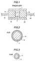
- the thermistor is constructed by putting thermistor element 2 in glass tube 1, which is hermetically sealed by sealing electrodes 3A, 3B.
- the thermistor elements 2 is sandwiched by the electrodes 3A, 3B to maintain the electric contact therebetween.
- reference symbols 4A, 4B indicate lead wires electrically attached to the electrodes 3A, 3B, respectively.
- FIG. 2 shows a sectional view of an example of the dumet wire
- a dumet wire is constructed by coating core wire 11 made of iron-nickel alloy by copper 12 as an intermediate layer, which is further covered by surface layer 13 of cuprous oxide (Cu 2 O) or borate (Cu 2 O-Na 2 B 4 O 7 ).
- the core of a dumet wire is made of iron-nickel alloy in order to bring the thermal expansion coefficient closer to that of glass, whereas the surface layer thereof is made of cuprous oxide for the purpose of the good melting-adhesiveness with glass. Since the sealing electrode 3A, 3B is made by cutting such a dumet wire in an appropriate length, iron-nickel alloy as core material is exposed to the atmosphere at the end surface 3a, 3b.
- lead wire 4A, 4B is formed by coating the surface of core wire 15 made of dumet, iron or iron-nickel alloy with copper 14.
- Metallic portions of the glass-sealed type thermistor i.e., the outer end surfaces 3a, 3b of the sealing electrodes 3A, 3B and the surfaces of the lead wires 4A, 4B, are plated by solder to solder the thermistor onto a substrate. Further, nickeling can also be used to attach the thermistor to the substrate by spot welding or the like.
- the core of the dumet wire made of iron-nickel alloy is exposed to the atmosphere at the end surfaces 3a, 3b.
- the corrosion resistivity of the end surface 3a, 3b can be improved by solder-plating or nickeling.
- a thermistor of this kind is often used under the corrosive environment, such as a temperature sensitive resistor for measuring the temperature of intake air in an automobile. In such a case, the thermistor is required to have the sufficiently high corrosion resistivity.
- a conventional glass-sealed type thermistor as mentioned above does not have the sufficiently high corrosion resistivity and hence has a disadvantage that corrosion occurs when it is used under the heavily corrosive environment, such as sulfur dioxide gas atmosphere.
- a thermistor which has solder plating to cover its metallic portions, can not have the sufficiently high corrosion resistivity. Compared with that, a thermistor, which has nickeling for the same purpose, can be much improved in the corrosion resistivity.
- An object of the present invention solves the problem in a conventional electronic device as described above to thereby provide a structure of an electronic device, such as a thermistor, having the extremely high corrosion resistivity.
- a structure of an electronic device comprises an element with a desired electronic characteristic, electrodes electrically connected to the element, inorganic insulator for sealing or coating at least part of the element and the electrodes, and lead wires provided for the electrical connection with the electrodes, wherein the lead wires are made of corrosion resistant material and further at least a portion surrounding a joint of the lead wires and the electrodes is coated with corrosion resistant material.
- the lead wires themselves are made of corrosion resistant material, there occurs no corrosion in a welding portion and a cut portion. Further, since the lead wires and the exposed portion of the electrodes are coated with corrosion resistant material, it is possible to provide a structure of an electronic device having the extremely high corrosion resistivity and hence the high durability as well as high reliability. As a result, an electronic device with a structure according to the present invention can be used for a long period without corrosion under the heavily corrosive environment, such as sulfur dioxide gas atmosphere.
- an axial type of a glass-sealed thermistor may be constructed in the following manner; namely, first of all, cylindrical electrodes made of dumet wire are welded with lead wires made of nickel. Then, a semiconductor thermistor element and the cylindrical electrodes are put in a glass tube in such a manner that the electrodes hermetically seal both ends of the glass tube. Further, nikeling is performed on an exposed portion of the electrodes and the lead wires, as well as the welded portion of the lead wires with the electrodes.
- a linear type of a temperature sensitive resistor with lead wires may be constructed as follows; namely, at first, a temperature sensitive element is made by forming a metallic film on the surface of a cylindrical alumina bobbin. Cap electrodes made of iron-nickel alloy are fitted by pressure to both ends of the temperature sensitive element as formed above. Then, lead wires made of nickel are welded to the cap electrodes. Part of the temperature sensitive element and the electrodes are coated with glass, and nickeling is performed on an exposed portion of the cap electrodes and the lead wires, as well as the welded portion of the lead wires with the cap electrodes.
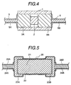
- FIG. 4 is a cross-sectional view of an axial type of a glass-sealed thermistor in accordance with an embodiment of the present invention, in which the same reference numerals or symbols as those used in FIG. 1 indicate the same parts.
- the glass-sealed type thermistor is constructed as follows. Namely, the glass tube 1 has the thermistor element 2 therein. Both ends of the glass tube 1 are hermetically sealed by the sealing electrodes 3A, 3B, to which nickel lead wires 5A, 5B are attached. Nickel member 6 is plated on metallic portions of an assembly as described above, i.e., outer end surface of the electrodes 3A, 3B and surface of the lead wires 5A, 5B.
- dumet wire for the sealing electrodes 3A, 3B in the same manner as conventional. Further, there is no limitation in the length and diameter of the electrode 3A, 3B.
- the glass tube 1 can be formed by a glass tube made of SiO 2 -PbO-K 2 O or the like in the same manner as conventional. Thickness of the glass tube 1 depends on the size of the thermistor element 2, but is generally 0.3 ⁇ 1.0 mm. Preferably, an inner diameter of the glass tube 1 is 1 ⁇ 1.8 times as large as the diameter of the thermistor element 2 to be inserted therein and a length thereof is 3 ⁇ 50 times as large as the thickness of the thermistor element 2.
- the thermistor element 2 has a thermistor ceramic with electrodes made of Ag, Pd or the like on both side thereof.
- the size of the thermistor element 2 is usually 0.35 ⁇ 0.6 mm square.
- the nickel lead wires 5A, 5B are a wire of 0.3 ⁇ 0.5 mm in diameter.
- the thickness of the nickeling is preferably 2 ⁇ 10 ⁇ m, since it is difficult to obtain the sufficient effect of improving the corrosion resistivity, if it is much thinner than the thickness as above, and it is uneconomical, if it is much thicker than that.
- the lead wires 5A, 5B can also be nickeled resultantly.
- the inventors carried out the test that the glass-sealed type thermistor as above has been spot-welded onto a substrate and used under the sulfur dioxide gas atmosphere for a long period. No occurrence of corrosion could be found in that test, however.
- FIG. 5 is a cross-sectional view of a linear type of a temperature sensitive resistor in accordance with another embodiment of the present invention.
- a temperature sensitive element according to this embodiment is constructed as follows. Thin platinum film 22 is formed by barrel spatter on the surface of solid cylindrical bobbin 21 made of alumina having a diameter of nearly 1 mm. The bobbin 21 with the platinum film 22 is further treated by heating.
- Cap electrodes 23A, 23B made of iron-nickel alloy are fitted by pressure on both ends of the temperature sensitive element, to which electrodes nickel lead wires 24A, 24B having a diameter of 0.3 ⁇ 0.5 mm are welded
- the electronic device according to the present invention can be used for a long period without corrosion under the heavily corrosive environment, such as sulfur dioxide gas atmosphere.
Landscapes
- Engineering & Computer Science (AREA)
- Microelectronics & Electronic Packaging (AREA)
- Manufacturing & Machinery (AREA)
- Thermistors And Varistors (AREA)
Abstract
Description
Claims (4)
- A structure of an electronic device comprising an element (2) with a desired electronic characteristic; electrodes (3A, B) for making the electrical connection with said element; inorganic insulator (1) for coating at least part of said element (2) and said electrodes; and lead wires (5A, B) provided for the electrical connection with said electrodes; characterized in that said lead wire (5A, B) is made of a corrosion resistant material and at least a portion (6) surrounding a joint of said lead wires and said electrodes is coated with corrosion resistant material.
- A structure of an electronic device according to claim 1, wherein the portion (6) surrounding the joint of said lead wires (5A, B) and said electrodes (3A, B) includes said lead wires and a metallic portion of said electrodes which is exposed to the external atmosphere.
- A structure of an electronic device according to any one of claims 1 and 2, wherein said lead wire is made of nickel, and nickel is plated at least on the portion (6) surrounding the joint of said lead wires and said electrodes.
- A structure of an electronic device according to claim 1, wherein said element (2) is a thermistor made of a semiconductor material having a temperature dependent characteristic, said electrodes for electrically connecting to said element are formed by dumet wire, and said inorganic insulator for coating at least part of said element and said electrodes is glass material.
Applications Claiming Priority (3)
| Application Number | Priority Date | Filing Date | Title |
|---|---|---|---|
| JP8211193A JPH1055903A (en) | 1996-08-09 | 1996-08-09 | Electronic component structure |
| JP211193/96 | 1996-08-09 | ||
| JP21119396 | 1996-08-09 |
Publications (2)
| Publication Number | Publication Date |
|---|---|
| EP0824258A1 true EP0824258A1 (en) | 1998-02-18 |
| EP0824258B1 EP0824258B1 (en) | 2004-10-20 |
Family
ID=16601932
Family Applications (1)
| Application Number | Title | Priority Date | Filing Date |
|---|---|---|---|
| EP97113695A Expired - Lifetime EP0824258B1 (en) | 1996-08-09 | 1997-08-07 | Structure of electronic device |
Country Status (6)
| Country | Link |
|---|---|
| US (1) | US6344790B1 (en) |
| EP (1) | EP0824258B1 (en) |
| JP (1) | JPH1055903A (en) |
| KR (1) | KR19980018505A (en) |
| CN (1) | CN1123014C (en) |
| DE (1) | DE69731265T2 (en) |
Cited By (3)
| Publication number | Priority date | Publication date | Assignee | Title |
|---|---|---|---|---|
| EP1562029A1 (en) * | 2004-02-06 | 2005-08-10 | Hitachi, Ltd. | Temperature sensor |
| WO2013037548A1 (en) * | 2011-09-16 | 2013-03-21 | Robert Bosch Gmbh | Measuring resistor for current sensor and current sensor unit |
| WO2014000854A1 (en) * | 2012-06-29 | 2014-01-03 | Isabellenhütte Heusler Gmbh & Co. Kg | Resistor, particularly a low-resistance current-measuring resistor |
Families Citing this family (7)
| Publication number | Priority date | Publication date | Assignee | Title |
|---|---|---|---|---|
| DE10153217B4 (en) * | 2001-10-31 | 2007-01-18 | Heraeus Sensor Technology Gmbh | Sheathed wire, in particular connecting wire for electrical temperature sensors |
| KR100436583B1 (en) * | 2001-11-13 | 2004-06-19 | 엘지전선 주식회사 | Ptc Circuit Overcurrent Protection Device Contained Within Insulating Tube |
| JP4724355B2 (en) * | 2003-03-31 | 2011-07-13 | ルネサスエレクトロニクス株式会社 | Semiconductor device |
| JP4363226B2 (en) * | 2003-07-17 | 2009-11-11 | 三菱マテリアル株式会社 | surge absorber |
| DE102008053025B4 (en) | 2008-10-24 | 2023-03-30 | Cummins Filtration Ip, Inc. | Apparatus, system and method for detecting temperature threshold events in an aftertreatment device |
| JP6439558B2 (en) * | 2015-04-07 | 2018-12-19 | 富士電機株式会社 | Power semiconductor modules and connection pins |
| CN113963875B (en) * | 2021-10-09 | 2024-09-24 | 成都宏明电子股份有限公司 | End cover type cylindrical thermistor and preparation method thereof |
Citations (8)
| Publication number | Priority date | Publication date | Assignee | Title |
|---|---|---|---|---|
| JPS5596665A (en) * | 1979-01-19 | 1980-07-23 | Totoku Electric Co Ltd | Lead component for semiconductor element |
| JPS56103454A (en) * | 1980-01-22 | 1981-08-18 | Toshiba Corp | Slaglead |
| EP0129997A1 (en) * | 1983-06-11 | 1985-01-02 | Chichibu Cement Co., Ltd. | Process for the production of PTC thermistors |
| EP0171877A1 (en) * | 1984-08-02 | 1986-02-19 | Stc Plc | Method of securing leads to a thermistor |
| JPS6367761A (en) * | 1986-09-09 | 1988-03-26 | Shinko Electric Ind Co Ltd | Air-tight glass terminal |
| JPH02164004A (en) * | 1988-12-19 | 1990-06-25 | Matsushita Electric Ind Co Ltd | Manufacture of glass-sealed thermistor |
| JPH07312301A (en) * | 1994-03-24 | 1995-11-28 | Ngk Insulators Ltd | Resistor element |
| US5506071A (en) * | 1992-02-27 | 1996-04-09 | Mitsubishi Materials Corporation | Sealing electrode and surge absorber using the same |
Family Cites Families (5)
| Publication number | Priority date | Publication date | Assignee | Title |
|---|---|---|---|---|
| US4016527A (en) * | 1975-09-25 | 1977-04-05 | North American Philips Corporation | Hermetically sealed film resistor |
| JPS559665A (en) | 1978-07-07 | 1980-01-23 | Seiko Epson Corp | Liquid crystal composition |
| US4276536A (en) * | 1979-09-04 | 1981-06-30 | Scully Electronic Systems, Inc. | Self-heating thermistor probe for low temperature applications |
| US4512871A (en) * | 1983-05-09 | 1985-04-23 | Ngk Insulators, Ltd. | Oxygen sensor with heater |
| JPH076853A (en) * | 1993-04-03 | 1995-01-10 | Patent Puromooto Center:Kk | Gap discharge element and its manufacture |
-
1996
- 1996-08-09 JP JP8211193A patent/JPH1055903A/en active Pending
-
1997
- 1997-08-07 DE DE69731265T patent/DE69731265T2/en not_active Expired - Fee Related
- 1997-08-07 EP EP97113695A patent/EP0824258B1/en not_active Expired - Lifetime
- 1997-08-08 CN CN97117322A patent/CN1123014C/en not_active Expired - Fee Related
- 1997-08-08 KR KR1019970037896A patent/KR19980018505A/en not_active Ceased
- 1997-08-11 US US08/907,881 patent/US6344790B1/en not_active Expired - Fee Related
Patent Citations (8)
| Publication number | Priority date | Publication date | Assignee | Title |
|---|---|---|---|---|
| JPS5596665A (en) * | 1979-01-19 | 1980-07-23 | Totoku Electric Co Ltd | Lead component for semiconductor element |
| JPS56103454A (en) * | 1980-01-22 | 1981-08-18 | Toshiba Corp | Slaglead |
| EP0129997A1 (en) * | 1983-06-11 | 1985-01-02 | Chichibu Cement Co., Ltd. | Process for the production of PTC thermistors |
| EP0171877A1 (en) * | 1984-08-02 | 1986-02-19 | Stc Plc | Method of securing leads to a thermistor |
| JPS6367761A (en) * | 1986-09-09 | 1988-03-26 | Shinko Electric Ind Co Ltd | Air-tight glass terminal |
| JPH02164004A (en) * | 1988-12-19 | 1990-06-25 | Matsushita Electric Ind Co Ltd | Manufacture of glass-sealed thermistor |
| US5506071A (en) * | 1992-02-27 | 1996-04-09 | Mitsubishi Materials Corporation | Sealing electrode and surge absorber using the same |
| JPH07312301A (en) * | 1994-03-24 | 1995-11-28 | Ngk Insulators Ltd | Resistor element |
Non-Patent Citations (5)
| Title |
|---|
| PATENT ABSTRACTS OF JAPAN vol. 004, no. 145 (E - 029) 14 October 1980 (1980-10-14) * |
| PATENT ABSTRACTS OF JAPAN vol. 005, no. 176 (E - 081) 12 November 1981 (1981-11-12) * |
| PATENT ABSTRACTS OF JAPAN vol. 012, no. 291 (E - 644) 9 August 1988 (1988-08-09) * |
| PATENT ABSTRACTS OF JAPAN vol. 014, no. 425 (E - 0977) 13 September 1990 (1990-09-13) * |
| PATENT ABSTRACTS OF JAPAN vol. 096, no. 003 29 March 1996 (1996-03-29) * |
Cited By (4)
| Publication number | Priority date | Publication date | Assignee | Title |
|---|---|---|---|---|
| EP1562029A1 (en) * | 2004-02-06 | 2005-08-10 | Hitachi, Ltd. | Temperature sensor |
| WO2013037548A1 (en) * | 2011-09-16 | 2013-03-21 | Robert Bosch Gmbh | Measuring resistor for current sensor and current sensor unit |
| WO2014000854A1 (en) * | 2012-06-29 | 2014-01-03 | Isabellenhütte Heusler Gmbh & Co. Kg | Resistor, particularly a low-resistance current-measuring resistor |
| US9437353B2 (en) | 2012-06-29 | 2016-09-06 | Isabellenhuette Heusler Gmbh & Co. Kg | Resistor, particularly a low-resistance current-measuring resistor |
Also Published As
| Publication number | Publication date |
|---|---|
| EP0824258B1 (en) | 2004-10-20 |
| KR19980018505A (en) | 1998-06-05 |
| CN1173719A (en) | 1998-02-18 |
| US6344790B1 (en) | 2002-02-05 |
| CN1123014C (en) | 2003-10-01 |
| DE69731265D1 (en) | 2004-11-25 |
| JPH1055903A (en) | 1998-02-24 |
| DE69731265T2 (en) | 2005-02-24 |
Similar Documents
| Publication | Publication Date | Title |
|---|---|---|
| CA1067613A (en) | Hermetically sealed film resistor | |
| US4612529A (en) | Subminiature fuse | |
| US6297723B1 (en) | Temperature sensor and method of manufacturing the same | |
| US5726624A (en) | Temperature sensor with internal rigid substrate | |
| EP0824258B1 (en) | Structure of electronic device | |
| GB2162686A (en) | Thermistors | |
| KR100994656B1 (en) | Surge absorber | |
| US8359905B2 (en) | Ceramic heater and gas sensor including the same | |
| KR101054629B1 (en) | Surge Absorbers and Manufacturing Method Thereof | |
| US4834863A (en) | Oxygen sensor having a heater | |
| JP7538367B2 (en) | Temperature Sensor | |
| JP4544255B2 (en) | Electronic component enclosure | |
| JP2515067Y2 (en) | Thermistor temperature sensor | |
| JPH1183641A (en) | Glass sealed thermistor | |
| JP4464801B2 (en) | Gas sensor | |
| JP3705362B2 (en) | Sealed thermal device | |
| JP3601320B2 (en) | surge absorber | |
| US20040095987A1 (en) | Temperature probe and its use | |
| JP2000068102A (en) | Resistor | |
| US5186809A (en) | Structure for joining a wire to a solid electrolytic element | |
| JPH0313993Y2 (en) | ||
| GB2032191A (en) | Improvements in Electrical Resistors | |
| JPH1022042A (en) | Electronic component enclosure | |
| JPS6240404Y2 (en) | ||
| JP2518214Y2 (en) | Low power fusing type fuse resistor |
Legal Events
| Date | Code | Title | Description |
|---|---|---|---|
| PUAI | Public reference made under article 153(3) epc to a published international application that has entered the european phase |
Free format text: ORIGINAL CODE: 0009012 |
|
| 17P | Request for examination filed |
Effective date: 19971114 |
|
| AK | Designated contracting states |
Kind code of ref document: A1 Designated state(s): DE FR GB IT |
|
| AX | Request for extension of the european patent |
Free format text: AL;LT;LV;RO;SI |
|
| AKX | Designation fees paid |
Free format text: DE FR GB IT |
|
| RBV | Designated contracting states (corrected) |
Designated state(s): DE FR GB IT |
|
| GRAP | Despatch of communication of intention to grant a patent |
Free format text: ORIGINAL CODE: EPIDOSNIGR1 |
|
| GRAS | Grant fee paid |
Free format text: ORIGINAL CODE: EPIDOSNIGR3 |
|
| GRAA | (expected) grant |
Free format text: ORIGINAL CODE: 0009210 |
|
| AK | Designated contracting states |
Kind code of ref document: B1 Designated state(s): DE FR GB IT |
|
| REG | Reference to a national code |
Ref country code: GB Ref legal event code: FG4D |
|
| REF | Corresponds to: |
Ref document number: 69731265 Country of ref document: DE Date of ref document: 20041125 Kind code of ref document: P |
|
| ET | Fr: translation filed | ||
| PLBE | No opposition filed within time limit |
Free format text: ORIGINAL CODE: 0009261 |
|
| STAA | Information on the status of an ep patent application or granted ep patent |
Free format text: STATUS: NO OPPOSITION FILED WITHIN TIME LIMIT |
|
| 26N | No opposition filed |
Effective date: 20050721 |
|
| PGFP | Annual fee paid to national office [announced via postgrant information from national office to epo] |
Ref country code: DE Payment date: 20080908 Year of fee payment: 12 |
|
| PGFP | Annual fee paid to national office [announced via postgrant information from national office to epo] |
Ref country code: IT Payment date: 20080716 Year of fee payment: 12 Ref country code: FR Payment date: 20080723 Year of fee payment: 12 |
|
| PGFP | Annual fee paid to national office [announced via postgrant information from national office to epo] |
Ref country code: GB Payment date: 20080724 Year of fee payment: 12 |
|
| GBPC | Gb: european patent ceased through non-payment of renewal fee |
Effective date: 20090807 |
|
| REG | Reference to a national code |
Ref country code: FR Ref legal event code: ST Effective date: 20100430 |
|
| PG25 | Lapsed in a contracting state [announced via postgrant information from national office to epo] |
Ref country code: FR Free format text: LAPSE BECAUSE OF NON-PAYMENT OF DUE FEES Effective date: 20090831 Ref country code: DE Free format text: LAPSE BECAUSE OF NON-PAYMENT OF DUE FEES Effective date: 20100302 |
|
| PG25 | Lapsed in a contracting state [announced via postgrant information from national office to epo] |
Ref country code: GB Free format text: LAPSE BECAUSE OF NON-PAYMENT OF DUE FEES Effective date: 20090807 |
|
| PG25 | Lapsed in a contracting state [announced via postgrant information from national office to epo] |
Ref country code: IT Free format text: LAPSE BECAUSE OF NON-PAYMENT OF DUE FEES Effective date: 20090807 |