EP0824191A2 - Kompressor mit variabler Fördermenge - Google Patents
Kompressor mit variabler Fördermenge Download PDFInfo
- Publication number
- EP0824191A2 EP0824191A2 EP97113875A EP97113875A EP0824191A2 EP 0824191 A2 EP0824191 A2 EP 0824191A2 EP 97113875 A EP97113875 A EP 97113875A EP 97113875 A EP97113875 A EP 97113875A EP 0824191 A2 EP0824191 A2 EP 0824191A2
- Authority
- EP
- European Patent Office
- Prior art keywords
- drive shaft
- swash plate
- crankcase
- cylinder block
- bore
- Prior art date
- Legal status (The legal status is an assumption and is not a legal conclusion. Google has not performed a legal analysis and makes no representation as to the accuracy of the status listed.)
- Granted
Links
- 238000006073 displacement reaction Methods 0.000 title claims abstract description 60
- 239000003507 refrigerant Substances 0.000 claims abstract description 52
- 230000002093 peripheral effect Effects 0.000 claims abstract description 25
- 239000012530 fluid Substances 0.000 claims abstract description 18
- 238000004891 communication Methods 0.000 claims abstract description 9
- 238000004378 air conditioning Methods 0.000 claims description 12
- 230000004323 axial length Effects 0.000 claims description 6
- 230000009471 action Effects 0.000 claims description 2
- 238000001816 cooling Methods 0.000 abstract description 15
- 230000008859 change Effects 0.000 description 8
- XEEYBQQBJWHFJM-UHFFFAOYSA-N Iron Chemical group [Fe] XEEYBQQBJWHFJM-UHFFFAOYSA-N 0.000 description 6
- 230000000740 bleeding effect Effects 0.000 description 6
- 230000007423 decrease Effects 0.000 description 6
- 230000003247 decreasing effect Effects 0.000 description 6
- 230000004044 response Effects 0.000 description 6
- 230000006870 function Effects 0.000 description 5
- 230000006835 compression Effects 0.000 description 4
- 238000007906 compression Methods 0.000 description 4
- 238000012544 monitoring process Methods 0.000 description 3
- 230000008901 benefit Effects 0.000 description 2
- 230000007246 mechanism Effects 0.000 description 2
- 230000003134 recirculating effect Effects 0.000 description 2
- 230000035939 shock Effects 0.000 description 2
- 230000004308 accommodation Effects 0.000 description 1
- 230000001143 conditioned effect Effects 0.000 description 1
- 238000010276 construction Methods 0.000 description 1
- 230000000694 effects Effects 0.000 description 1
- 239000010687 lubricating oil Substances 0.000 description 1
- 238000005461 lubrication Methods 0.000 description 1
- 238000003754 machining Methods 0.000 description 1
- 239000003921 oil Substances 0.000 description 1
- 230000000717 retained effect Effects 0.000 description 1
Images


Classifications
-
- F—MECHANICAL ENGINEERING; LIGHTING; HEATING; WEAPONS; BLASTING
- F04—POSITIVE - DISPLACEMENT MACHINES FOR LIQUIDS; PUMPS FOR LIQUIDS OR ELASTIC FLUIDS
- F04B—POSITIVE-DISPLACEMENT MACHINES FOR LIQUIDS; PUMPS
- F04B27/00—Multi-cylinder pumps specially adapted for elastic fluids and characterised by number or arrangement of cylinders
- F04B27/08—Multi-cylinder pumps specially adapted for elastic fluids and characterised by number or arrangement of cylinders having cylinders coaxial with, or parallel or inclined to, main shaft axis
- F04B27/14—Control
- F04B27/16—Control of pumps with stationary cylinders
- F04B27/18—Control of pumps with stationary cylinders by varying the relative positions of a swash plate and a cylinder block
- F04B27/1804—Controlled by crankcase pressure
-
- F—MECHANICAL ENGINEERING; LIGHTING; HEATING; WEAPONS; BLASTING
- F04—POSITIVE - DISPLACEMENT MACHINES FOR LIQUIDS; PUMPS FOR LIQUIDS OR ELASTIC FLUIDS
- F04B—POSITIVE-DISPLACEMENT MACHINES FOR LIQUIDS; PUMPS
- F04B27/00—Multi-cylinder pumps specially adapted for elastic fluids and characterised by number or arrangement of cylinders
- F04B27/08—Multi-cylinder pumps specially adapted for elastic fluids and characterised by number or arrangement of cylinders having cylinders coaxial with, or parallel or inclined to, main shaft axis
- F04B27/10—Multi-cylinder pumps specially adapted for elastic fluids and characterised by number or arrangement of cylinders having cylinders coaxial with, or parallel or inclined to, main shaft axis having stationary cylinders
- F04B27/1036—Component parts, details, e.g. sealings, lubrication
- F04B27/1054—Actuating elements
- F04B27/1063—Actuating-element bearing means or driving-axis bearing means
-
- F—MECHANICAL ENGINEERING; LIGHTING; HEATING; WEAPONS; BLASTING
- F04—POSITIVE - DISPLACEMENT MACHINES FOR LIQUIDS; PUMPS FOR LIQUIDS OR ELASTIC FLUIDS
- F04B—POSITIVE-DISPLACEMENT MACHINES FOR LIQUIDS; PUMPS
- F04B49/00—Control, e.g. of pump delivery, or pump pressure of, or safety measures for, machines, pumps, or pumping installations, not otherwise provided for, or of interest apart from, groups F04B1/00 - F04B47/00
- F04B49/22—Control, e.g. of pump delivery, or pump pressure of, or safety measures for, machines, pumps, or pumping installations, not otherwise provided for, or of interest apart from, groups F04B1/00 - F04B47/00 by means of valves
- F04B49/225—Control, e.g. of pump delivery, or pump pressure of, or safety measures for, machines, pumps, or pumping installations, not otherwise provided for, or of interest apart from, groups F04B1/00 - F04B47/00 by means of valves with throttling valves or valves varying the pump inlet opening or the outlet opening
Definitions
- the present invention relates to a variable displacement refrigerant compressor adapted for use in an automotive air conditioning system dispensing with a clutching mechanism between the compressor and an automotive engine that drives the compressor. More specifically, the invention relates to a variable displacement compressor of the type that shuts off a flow of refrigerant gas into a suction chamber while the compressor is placed in its minimum displacement position, by using a shutoff member in the form of a spool incorporated in a central bore formed through a cylinder block of the compressor.
- variable displacement refrigerant compressor of the same type as that of the present invention will be explained.
- the compressor comprises a housing defining therein a crankcase, a suction chamber receiving refrigerant gas before compression and a discharge chamber receiving refrigerant gas after compression.
- the housing includes a cylinder block having a front end surface exposed to the crankcase and defining therein a plurality of cylinder bores each receiving therein a working piston.
- the compressor further comprises a drive shaft rotatably supported in the crankcase, a swash plate supported on the drive shaft for rotation therewith and tiltable with respect to the axis of the drive shaft between the minimum and maximum tilt angle positions while moving along the drive shaft, thereby making a wobbling movement at a variable tilt angle.
- the above piston slidably received in each of the cylinder bores is operatively connected to the swash plate such that the wobbling movement of the swash plate at the variable tilt angle is converted into reciprocal movement of the piston with a variable length of stroke in the associated cylinder bore.
- the housing further defines therein a suction passage receiving an inflow of refrigerant gas from an air conditioning system, in which the compressor is connected, and communicable with the suction chamber.
- the cylinder block has formed axially therethrough a central bore in alignment with the drive shaft, one end of which bore is opened into the crankcase and the other end of which is opened into the suction passage.
- the compressor further comprises shutoff means in the form of a cup-shaped spool slidably disposed in the above central bore for shutting off fluid communication between the suction passage and the suction chamber to stop the inflow of refrigerant gas into the cylinder bores when the swash plate is brought to the position for minimum displacement.
- the rear end portion of the drive shaft is inserted into the shutoff spool and supported by a radial bearing mounted on the drive shaft within the shutoff spool.
- the compressor further includes a displacement control valve for controlling the tilt angle of the swash plate in response to a change in the cooling demand or load.
- the swash plate is caused to tilt in response to the difference between the pressure prevailing in the crankcase and the pressure in the cylinder bores.
- the swash plate is brought to a tilt angle position for minimum displacement of the compressor and the shutoff spool is moved in the central bore to close the suction passage so that the flow of refrigerant gas into the suction chamber is shut off.
- the refrigerant gas within the compressor is circulated through the discharge chamber, crankcase, suction chamber and cylinder bores and, simultaneously, lubrication oil contained in and entrained by the refrigerant gas lubricates the internal parts of the compressor.
- compressor of the above type there has been no disclosure with reference to the arrangement of the radial bearing relative to the central bore of the cylinder block in which the bearing is slidably disposed.
- a compressor of the above type having a relatively short axial dimension of cylinder block and hence of the central bore receiving therein the shutoff spool, there has been recognized a fear that the above radial bearing may slide to such an extent that the center of that radial bearing, as defined by an imaginary plane extending perpendicularly to the drive shaft axis and passing through the mid point as determined along the axial direction of the drive shaft, comes out of the central bore or beyond the above front end surface of the cylinder block while the swash plate is being moved toward its maximum tilt angle position.
- shutoff spool tends to be inclined within the central bore with respect to the axis of the drive shaft and brought out of alignment with the above axis.
- the shutoff spool may fail to completely shut off the suction passage so that part of the refrigerant gas in the suction passage may flow into the suction chamber, with the result that cooling operation is performed in spite that there is no demand for cooling.
- an object of the invention is to provide a compressor of the above type in which the shutoff spool can be prevented from being inclined in the central bore of the cylinder block to permit the shutoff spool to completely close the suction passage when the swash plate is moved to its minimum displacement position.
- variable displacement refrigerant compressor is substantially the same as the type of compressor which was explained under the above BACKGROUND OF THE INVENTION, the description of the general construction of the compressor will not be reproduced here.
- the compressor according to the invention includes a suction chamber for receiving gas from an external circuit through a suction passage and a drive shaft extending in a crank case.
- a swash plate is tiltably mounted on the drive shaft to drive a piston in a cylinder bore to compress the gas.
- a shutoff body is movable in the axial direction with respect to the drive shaft. The shutoff body moves in association with the tilt action of the swash plate. The shutoff body closes the suction passage in association with the swash plate held at a minimum tilt angle. Keeping means keeps the shutoff body in parallel with the drive shaft.
- the compressor comprises a housing defining therein a crankcase and having a cylinder block.
- the cylinder block defines therein a cylinder bore.
- a drive shaft is rotatably supported in the crankcase.
- a swash plate is supported on the drive shaft for rotation therewith in unison.
- the swash plate is tiltable between a maximum tilt angle and a minimum tilt angle with respect to a plane perpendicularly extending to an axis of the drive shaft while moving along the drive shaft.
- a piston is slidably received in the cylinder bore and is operably connected to the swash plate such that rotation of the swash plate is converted into reciprocal movement of the piston with a variable stroke in the associated cylinder bore.
- a fluid passage has an inlet and an outlet.
- the cylinder block has a receiving bore axially extending therethrough in alignment with the drive shaft.
- the receiving bore has an inner peripheral surface and opens to the crankcase.
- the drive shaft has an end extending to the receiving bore.
- Shutoff means is slidably disposed in the receiving bore between the end of the drive shaft and the inner peripheral surface of the receiving bore to shut off the fluid passage.
- the shutoff means has a first section contacting the drive shaft and a second section contacting the inner peripheral surface.
- the second section has a mid point with respect to an axial length thereof.
- An imaginary plane perpendicularly extends to the axis of the drive shaft and passes through the mid point lies within the axial length of the first section.
- variable displacement refrigerant compressor of the invention will describe a preferred embodiment of variable displacement refrigerant compressor of the invention with reference to FIGS. 1 to 5.
- the compressor comprises a housing assembly including a cylinder block 11, a front housing 12 clamped to the front end of the cylinder block and a rear housing 13 secured to the rear end of the cylinder block with a valve plate 14 interposed therebetween.
- the front housing 12 cooperates with the cylinder block 11 to define therebetween a crankcase 15.
- a drive shaft 16 rotatably supported at the front end portion by the front housing 12 and at the opposite rear end portion by the cylinder block 11 by way of a radial bearing 30 and a shutoff member 28 in the form of a slidable spool, both of which will he described in detail in later part hereof.
- the front end of the drive shaft 16 extends out of the crankcase 15, and a pulley 17 is fastened to the front end surface of the drive shaft and rotatably supported on a front extension of the front housing 12 by way of an angular bearing 19 for carrying both axial and radial loads applied to the pulley 17.
- the pulley 17 is operatively connected to an engine of a vehicle (not shown) with no intervention of any clutching device.
- a lip seal 20 is provided between the drive shaft 16 and the front housing 12 to seal the crankcase 15.
- a lug plate or a rotor 21 is fixedly mounted on the drive shaft 16 for rotation therewith, and a swash plate 22 is supported on the drive shaft 16 slidably along and tiltably with respect to the drive shaft 16.
- the swash plate 22 has a pair of guide pins 23 (only one shown in the drawings) each having at its distal end a spherical guide portion which is slidably received in its associated one of paired guide holes 25 formed at the respective distal end of a pair of guide arms 24 (only one shown in the drawings) extending from the rotor 21.
- the extent of tilt angle of the swash plate 22 is defined with respect to an imaginary plane extending perpendicularly to the axis of the drive shaft 16.
- the swash plate 22 decreases its tilt angle while shifting its axial center toward the cylinder block 11.
- the rotor 21 is formed on its rear surface with a stop 21a into which a front surface of the swash plate 22 is brought in contact when the swash plate 22 is tilted to its maximum angle position as shown in FIG. 1.
- a spring 26 for urging the swash plate 22 toward its minimum angle position by pushing swash plate 22 toward the cylinder block 11.
- the cylinder block 11 is formed therethrough with a central bore 27 in alignment or coaxial with the drive shaft 16 and having the same diameter throughout its axial length.
- the central bore 27 slidably accommodates therein the aforementioned shutoff spool 28 which performs the function of shutting off the inflow of refrigerant gas into the compressor as will be described in detail in later part hereof.
- the shutoff spool 28 is of a hollow cylinder with a stepped configuration having a large diameter section 28a having an open end and a small diameter section 28b having a closed end. As shown in FIG.
- the rear end portion of the drive shaft 16 is received in the shutoff spool 28 and supported by the aforementioned radial bearing 30 which is fitted slidably between the inner peripheral surface of the large diameter section 28a of the shutoff spool 28 and the drive shaft 16, and retained in place within the shutoff spool 28 by a retainer 31.
- the central accommodation bore 27 of the cylinder block 11 is formed adjacent its rear end with an annular groove 27a in which a retainer 27b is removably held, and a spring 29 is disposed between this retainer 27b and the stepped portion between the large and small diameter sections 28a, 28b of the shutoff spool 28 for urging the shutoff spool 28 toward the swash plate 22 against the urging force exerted by the aforementioned spring 26.
- the urging force of this spring 29 is smaller than that of the spring 26 and, therefore, the resultant urging force of these two springs 26, 29 acts on the swash plate 22, a thrust bearing 34 which will described in detail later herein, and the shutoff spool 28 so as to shift them toward the rear housing 13.
- the cylinder block 11 is further formed therethrough with five axial cylinder bores 11a around the central bore 27, each slidably receiving therein a single-headed piston 35.
- Each piston 35 is engaged with the swash plate 22 by way of a pair of front and rear hemispherical shoes 36 in such a way that the wobbling movement of the swash plate 22 is converted into reciprocal sliding movement of the piston 35 in its associated cylinder bore 11a.
- the rear housing 13 is formed at its radial center a suction passage 32 in alignment with the drive shaft 16 and hence with the shutoff spool 28.
- This suction passage 32 is opened at its front end into the central bore 27 of the cylinder block 11 through a central opening in the valve plate 14.
- the valve plate 14 has adjacent its center opening an abutment stop surface 33 with which the rear end of the slidable shutoff spool 28 is brought into contact when the spool 28 is moved rearwardly to an extent to shut off the inflow of refrigerant gas flow into the compressor by closing the suction passage 32.
- the rear housing 13 cooperates with the valve plate 14 to form therein a suction chamber 37 and a discharge chamber 38 which are communicable with the cylinder bores 11a through suction ports 39 and discharge ports 40 formed through the valve plate 14, respectively.
- the valve plate 14 includes suction valves 41 and discharge valves 42 for controlling the fluid communication between the cylinder bores 11a and the suction and discharge chambers 37, 38 through the suction and discharge ports 39, 40, respectively.
- refrigerant gas in the suction chamber 37 is drawn through the suction port 39 into the cylinder bore 11a during suction stroke of the piston 35 when it is moved from its top dead center toward its bottom dead center, while the refrigerant gas in the cylinder bore 11a is compressed during the compression stroke of the piston then moving toward the top dead center and forced into the discharge chamber 38 when the pressure of the compressed gas is increased beyond a predetermined level that causes the discharge valve 42 to open.
- the maximum degree of discharge valve 42 opening is limited by a retainer 43.
- the suction chamber 37 in the rear housing 13 is communicable with the central bore 27 in the cylinder block 11 through a port 45 formed in the valve plate 14.
- the refrigerant gas introduced into the suction passage 32 from an external air conditioning circuit flows through this port 45 into the suction chamber 37.
- the shutoff spool 28 is moved into contact with the abutment surface 33, however, the fluid communication between the suction passage 32 and the suction chamber 37 is discontinued or shut off.
- the above-mentioned thrust bearing 34 is slidably supported on the drive shaft 16 between the swash plate 22 and the shutoff spool 28 for carrying an axial thrust exerted by the swash plate 22 and also preventing the rotation of the swash plate 22 from being transmitted to the shutoff spool 28.
- the drive shaft 16 has formed at its center an axial bleeding passage 46, the front end of which communicates with the crankcase 15 through an inlet port 46a adjacent the lip seal 20 and the rear end of which is opened into the interior of the shutoff spool 28 through an outlet port 46b.
- the shutoff spool 28 is formed with a bleeding port 47 providing fluid communication between the interior of the shutoff spool 28 and the central bore 27 in the cylinder block 11.
- the crankcase 15 is communicable with the suction chamber 37 for releasing the crankcase pressure.
- crankcase 15 is also communicable with the discharge chamber 38 through a passage 48 formed in the cylinder block 11, valve plate 14 and rear housing 13 and having on its way a displacement control valve assembly 49, which will be described in detail in later part hereof, for controllably changing the opening of the passage 48 by adjusting valve opening in the displacement control valve assembly 49.
- the part of the passage 48 which is formed in the rear housing 13 includes two passage portions, one extending from the discharge chamber 38 to the displacement control valve assembly 49 and the other from the valve assembly 49 to the passage portion in the valve plate 14.
- Reference numeral 51 designates a delivery port through which refrigerant gas compressed in the respective discharge chamber 38 is delivered to the external air conditioning circuit 52 in which the compressor is connected.
- the air conditioning circuit 52 includes a condenser 53 connected to the delivery port 51 of the compressor, an expansion valve 54, and an evaporator 55 connected to the suction passage 32 of the compressor.
- the expansion valve 54 is of the type that is operated automatically to control the flow of the refrigerant therethrough to the evaporator 55 in response to the refrigerant gas temperature at the outlet of the evaporator 55.
- the control computer 57 has connected to its inputs a device 58 for presetting a desired temperature of a car compartment to be air conditioned, a temperature sensor 59 for monitoring the current car compartment temperature, an on/off control switch 60 for turning on or off the air conditioning system and a speed sensor 61 for monitoring the current engine speed.
- the output of the control computer 57 is connected a drive circuit 62 which is in turn connected to a solenoid 63 incorporated in the aforementioned displacement control valve assembly 49.
- the control computer 57 responding to various input signals from the device 58, sensors 56, 59, 61 and the control switch 60, the control computer 57 generates to the drive circuit 62 a control signal representing a desired magnitude of electric current to be applied to the solenoid 63. It is noted that input current to the solenoid 63 may be determined from other additional input signals to the control computer 57 depending on further requirements of air conditioning, such as a signal representative of outside temperature.
- the displacement control valve assembly 49 comprises a valve housing 64 and a solenoid assembly 65 which are joined together into a single unit.
- the valve housing 64 and the solenoid assembly 65 cooperate to form therebetween a valve chamber 66 in which a valve 67 is movably disposed.
- the valve housing 64 has formed axially therein a bore 68 having one end thereof opened into the valve chamber 66 and the opposite end thereof into a bellows chamber 71 which communicates with the suction passage 32 through the passage 50 and an inlet port 72.
- a spring 69 is installed in the valve chamber 66 between the valve 67 and the end surface of the valve chamber 66 adjacent the axial bore 68 for urging the valve 67 downward, as seen in FIG. 1, away from the bore 68.
- the valve chamber 66 communicates with the discharge chamber 38 through a port 70 bored in the valve housing 64 and the passage 48 in the rear housing 13.
- the upper surface of the valve chamber 66 adjacent the opening of the bore 68 forms a valve seat against which the valve 67 may be brought into contact.
- the bellows chamber 71 communicates through an inlet port 72 and the passage 50 with the suction passage 32 and has incorporated therein a bellows 73 responsive to the suction pressure Ps and linked to the valve 67 by way of a rod 75 slidably inserted in the bore 68 and connected at its distal end to the valve 67.
- the bellows 73 is so arranged that it reduces its length thereby pulling the valve 67 upward as the suction pressure Ps applied thereto is increased, and increases the length to push the valve 67 as the suction pressure is decreased.
- the distal end portion of the rod 75 adjacent the valve 67 has a reduced diameter to provide a space or passage in the bore 68 for refrigerant gas to flow therethrough.
- a port 76 is formed in the valve housing 64 in the region of the bore 68 adjacent the reduced diameter portion of the rod 75, extending radially from the bore 68 and providing a fluid communicating between the crankcase 15 and above region of the bore 68 through the passage 48 in the rear housing 13, valve plate 14 and cylinder block 11. Therefore, when the valve 67 is opened to provide a fluid communication between the valve chamber 66 and the bore 68, the discharge chamber 38 communicates with the crankcase 15 through the passage 48 and displacement control valve assembly 49.
- the solenoid assembly 65 includes a stationary iron core 78 and a cylindrical cup-shaped iron core or a plunger 80 which is movably disposed immediately blow the stationary core 78.
- a spring 81 is provided in the plunger 80 for urging the same plunger toward its associated stationary core 78.
- This spring 81 has an urging force smaller than that of the spring 69 in the valve chamber 66.
- the iron core 78 has formed axially therethrough a guide bore 82 for slidably receiving therein a rod 83 which is formed integrally with the valve 67 and extends beyond the lower surface of the core 78.
- the rod 83 is urged so that its distal end is kept in contact with the plunger 80 under the influence of the resultant force from the urging forces of the springs 69 and 81, and the movement of the plunger 80 is transmitted to the rod 83 and hence to the valve 67 in the valve chamber 66.
- the solenoid assembly 65 further includes a coil or a cylindrical solenoid 63 disposed so as to surround adjacent respective parts of the stationary core 78 and the plunger 80, so that the plunger 80 is moved toward the stationary iron core 78 by magnetic attraction force which is developed when the solenoid 63 is energized.
- the solenoid 63 is energized in response to an electric current of a variable magnitude supplied from the drive circuit 62 which in turn responds to a control signal generated by the control computer 57.
- the attraction force or the distance of displacement of the plunger 80 toward the iron core 78 depends upon the magnitude of the energizing current.
- the front end surface of the cylinder block 11 is formed flat, and this flat surface is provided relative to the radial bearing 30 such that a plane defined by the flat end surface of the cylinder block 11 is positioned ahead of, i.e. further toward the swash plate 22 than, an imaginary plane P which extends perpendicularly to the axis of the drive shaft 16 and passing through the mid point of the radial bearing 30 as determined along the axis of the drive shaft on which the bearing is fitted.
- an imaginary plane P which extends perpendicularly to the axis of the drive shaft 16 and passing through the mid point of the radial bearing 30 as determined along the axis of the drive shaft on which the bearing is fitted.
- variable displacement refrigerant compressor The following will explain the operation of the above-described variable displacement refrigerant compressor.
- the control computer 57 commands the drive circuit 62 to energize the solenoid 63 with an electric current having a magnitude which is determined by a control signal then generated by the control computer 57. Accordingly, a magnetic attraction force corresponding to the current magnitude is developed to urge the plunger 80 toward the stationary iron core 78, so that the plunger 80 pushes the rod 83 and hence the valve 67 against the pressure of the spring 69 in a direction that reduce the valve opening, i.e. an opening defined between the valve 67 and its valve seat.
- the bellows 73 in the bellows chamber 71 is subjected to a suction pressure Ps of the refrigerant gas conducted through the passages 32 and 50. Accordingly, the bellows 73 is displaced to change its length and this displacement is transmitted to the valve 67 through the rod 75. As stated earlier, the bellows 73 reduces its length as the suction pressure Ps applied thereto is increased, and vice versa. Therefore, the position of the valve 67, which is subjected to the pressures exerted by the plunger 80, the spring 69 and the bellows 73, is determined by the equilibrium of these pressures.
- the suction pressure Ps becomes higher and the control computer 57 responding to such an increased cooling load commands the drive circuit 62 to energize solenoid 63 with a current of a greater magnitude. Accordingly, the plunger 80 is attracted toward the stationary core 78 by an increased attraction force thereby to reduce the valve opening. This increases the resultant force that reduces the valve opening. This in turn lowers the suction pressure Ps required for shifting the valve 67 in the direction to reduce the valve opening.
- the displacement control valve assembly 49 functions such that the suction pressure Ps required to reduce the valve opening is decreased to a lower level. With the valve opening thus reduced, the flow rate of refrigerant gas under discharge pressure Pd through the passage 48 into the crankcase 15 is reduced. On the other hand, part of the refrigerant gas in the crankcase 15 then flows into the suction chamber 37 through the bleeding passage 46 and the port 47, resulting in a decrease of the crankcase pressure Pc. Since the suction pressure Ps is higher under a greater cooling load, the pressure in the cylinder bores 11a is also higher. Accordingly, the difference between the crankcase pressure Pc and the pressure in the cylinder bores 11a becomes smaller, with the result that the swash plate 22 is moved to increases its tilt angle and the compressor operates for a larger displacement.
- valve 67 If the valve 67 is further moved into contact with its seat to close the bore 68, the flow of refrigerant gas under discharge pressure Pd into the crankcase 15 is stopped and, therefore, the crankcase pressure Pc becomes substantially the same as the suction pressure Ps, so that the swash plate 22 is brought to its maximum tilt angle position and the compressor operates for its maximum displacement.
- the stop 21a on the rear surface of the rotor 21 prevents the swash plate 22 to tilt further than the maximum tilt position.
- the suction pressure Ps becomes lower and the control computer 57 responding to such a decreased cooling demand commands the drive circuit 62 to energize solenoid 63 with a current of a smaller magnitude so that the plunger 80 is attracted toward the stationary core 78 by a decreased attraction force and the valve opening is increased.
- This increases the suction pressure Ps required for shifting the valve 67 in the direction to reduce the valve opening.
- the displacement control valve assembly 49 functions such that the suction pressure Ps required to reduce the valve opening is increased to a higher level.
- the control computer 57 commands the drive circuit 62 to de-energize the solenoid 63. Because the attraction force is no more available, the plunger 80 is moved to its lowermost position as shown in FIG. 3 under the influence of the spring 69 acting against the pressure of the spring 81. Because the valve 67 is then wide-open, refrigerant gas under discharge pressure Pd is drawn into the crankcase 15 to build up the crankcase pressure Pc. With such an increase of the crankcase pressure Pc, the swash plate 22 is moved to its minimum tilt angle position.
- control computer 57 also commands the drive circuit 62 to de-energize the solenoid 63 in response to an off signal from the control switch 60 of the air conditioning system. That is, when the air conditioner is turned off, the solenoid 63 is de-energized or turned off and, therefore, the swash plate 22 is kept in its minimum tilt angle position.
- the valve opening in the displacement control valve assembly 49 depends on the magnitude of an electric current applied to the solenoid 63. That is, when the solenoid 63 is energized by a current with a greater magnitude, the valve operation is performed under a lower suction pressure Ps. With the solenoid 63 energized by a current with a lower magnitude, on the other hand, the valve operation is performed under a higher suction pressure Ps.
- an electric current with a variable magnitude applied to the solenoid 63 changes the level of the suction pressure Ps required for reducing the valve opening and the displacement control valve assembly 49 adjusts the tilt angle of the swash plate 22 to control the compressor displacement so as to maintain the value of the suction pressure PS required for closing the valve 67.
- the displacement control valve assembly 49 performs the function of changing such value of the suction pressure Ps by varying the magnitude of input current to the solenoid 63 and also of allowing the compressor to operate in the state of minimum displacement regardless of the suction pressure Ps.
- the shutoff spool 28 As the swash plate 22 slides gradually toward the cylinder block 11 while reducing its tilt angle, the shutoff spool 28 is shifted accordingly while compressing the spring 29. Because the shutoff spool 28 continuously reduces the cross sectional area of the outlet opening of suction passage 32, the flow of refrigerant gas from the suction passage 32 into the suction chamber 37 is decreased. Accordingly, the volume of refrigerant gas introduced into the cylinder bores 11a from the suction chamber 37 is continuously reduced and, therefore, the drop in the delivery of compressed gas and hence of the discharge pressure Pd in the compressor takes place continuously. Such a continuous change of the discharge pressure Pd during the compressor operation from its maximum to minimum displacement prevents a rapid change in the torque to drive the compressor, with the result that a shock due to a rapid change in the torque can be forestalled.
- the shutoff spool 28 is simultaneously brought in contact with the abutment surface 33 of the valve plate 14 thereby to close the suction passage 32, as shown in FIG. 3, so that inflow of refrigerant gas from the air conditioning circuit 52 into the suction chamber 37 is shut off. Since the minimum tilt angle of the swash plate 22 is not 0 degree, but it represents a couples of degrees with respect to the aforementioned reference plane, as seen from FIG. 3, refrigerant gas in the cylinder bores 11a is discharged into the discharge chamber 38 as long as the engine is running to rotate the drive shaft 16 of the compressor.
- the refrigerant gas forced into the discharge chamber 38 flows through the passage 48 and the displacement control valve assembly 49, in which the valve 67 is then wide-open, into the crankcase 15, from where the gas flows further through the bleeding passage 46 in the drive shaft 16, port 47 in the shutoff spool 28 and port 45 in the valve plate 14 and then into the suction chamber 38.
- the refrigerant gas in the suction chamber 38 is again discharged into the discharge chamber 38.
- a recirculating passage is formed for the refrigerant gas to flow in the compressor when it is operating in the state of the minimum displacement and the compressor parts are lubricated by lubricating oil contained in and entrained by the recirculating refrigerant gas.
- the control computer 57 commands the drive circuit 62 to energize the solenoid 63 and the valve opening is reduced. This decreases the crankcase pressure Pc and the spring 29 starts to expand, causing the shutoff spool 28 to move clear of the abutment surface 33, with a simultaneous movement of the swash plate 22 toward its maximum angle position. As the swash plate 22 moves continuously toward the rotor 21 while increasing its tilt angle, the cross sectional area of the outlet opening of the suction passage 32 and hence the flow of refrigerant gas from the auction passage 32 into the suction chamber 37 is increased.
- the volume of refrigerant gas introduced into the cylinder bores 11a from the suction chamber 37 is continuously increased and, therefore, the delivery of compressed gas and hence the discharge pressure Pd in the compressor are also increased in a continuous manner.
- Such a continuous change of the discharge pressure Pd during the compressor operation from its minimum toward minimum displacement prevents a rapid change in the compressor driving torque, with the result that a shock due to a rapid change in the torque can be forestalled.
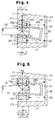
- Radial load FR applied to the drive shaft 16 during compressing operation of the pistons 35 is received by the inner peripheral surface of the central bore 27 via the radial bearing 30 and the shutoff spool 28. Supposing that the shutoff spool 28 is caused to incline relative to the axis of the drive shaft 16, as shown in FIG. 4, because of any external force such as vibration, the radial load FR is decomposed into two components F11 and F12 acting in opposite directions at contact points defined by the drive shaft 16 and the front and rear edges of the radial bearing 30, respectively, as shown in FIG. 4.
- shutoff spool 28 will not maintain the illustrated inclined position, but it will be turned about the point 01 to be brought in contact with the inner peripheral surface of the central bore 27 as shown in FIG. 5, whereupon the spool will resume a position in alignment with the drive shaft 16.
- the radial load FR is composed into two components F21 and F22 acting in the same direction at contact points defined by the drive shaft 16 and the front and rear edges of the radial bearing 30, respectively.
- a force F23 is developed at a contact point 02 defined by the outer peripheral surface of the large diameter section 28a of the shutoff spool 28 and the front edge of the central bore 27, and another force F24 at a contact point between the inner peripheral surface of the central bore 27 and the rear edge of the large diameter section 28a of the shutoff spool 28.
- shutoff spool 28 is subjected to a moment which acts around the point 02 and forces the shutoff spool 28 into contact with the inner peripheral surface of the central bore 27. To put in other words, the shutoff spool 28 is subjected to a moment that prevents it from being inclined relative to the drive shaft 16.
- the compressor of the above embodiment is constructed such that peripheral surface 27c on the front end of the cylinder block 11 adjacent the front opening of the central bore 27 is positioned ahead of the axial center of the radial bearing 30, as defined the plane P, even when the shutoff spool 28 is moved to its foremost position with the swash plate 22 tilted at its maximum angle, the shutoff spool 28 will not be inclined with respect to the drive shaft while the shutoff spool 28 is moving toward the rear housing 13 in conjunction with the movement of the swash plate 22 from the maximum toward minimum tilt angle position, with the result that the shutoff spool 28 can perform its intended function to shut off securely the suction passage 32 when the swash plate 22 is brought to the minimum tilt angle position where there exists no cooling demand.
- the compressor performs its minimum displacement operation without introducing refrigerant gas into the suction chamber 37 from the suction passage 32.
- the entire front end surface of the cylinder block 11 including the peripheral surface 27a is formed flat, the tendency for the shutoff spool 28 to incline can be further suppressed.
- the flat configuration of the front end surface is advantageous in machining the cylinder block 11.
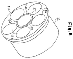
- FIG. 6 shows a second preferred embodiment of the variable displacement refrigerant compressor according to the present invention.
- This embodiment differs from the first embodiment in that the front end surface of the cylinder block 11 is provided at the peripheral area thereof adjacent the front opening of the central bore 27 with an annular projection 84 which is formed such that its radially inner circular surface forms a part of the inner peripheral surface of the central bore 27.
- the front end surface 84a of the annular projection 84 which corresponds to the peripheral surface 27c in the first embodiment, is formed flat.
- the front end surface 84a of the projection 84 on the cylinder block 11 is positioned ahead of the axial center of the radial bearing 30 when the shutoff spool 28 is moved to its foremost position.
- the same effects as achieved in the first embodiment can accomplished in this second embodiment, too.
- the cylinder block 11 of the second embodiment offers an advantage in that the compressor can be constructed compact because the axial dimension of the cylinder block 11 can be shortened by the axial length of the projection.
- the cylinder block may be formed on the front end surface thereof, other than the peripheral surface area 27c, with a recess.
- a separate fluid chamber may be provided in the compressor housing instead of utilizing the crankcase pressure Pc for the above purpose.
- the bleeding passage may be provided between the crankcase 15 and the suction chamber 37 and the displacement control valve assembly 49 is disposed in the bleeding passage.
- the above embodiments was described by way of a so-called clutchless compressor which can dispense with a clutching mechanism which, otherwise, is usually connected between a vehicle engine and the drive shaft of the compressor.
- the compressor according to the invention may be connected to a clutch.
- the clutch is kept engaged while the control switch 60 is on, but it is kept disengaged when the switch remains off, i.e. when there is no need for air conditioning and, therefore, the drive shaft of the compressor does not need be driven.
- a variable displacement refrigerant compressor which is of a type chat comprises a housing forming therein a crankcase, a suction chamber and a suction passage communicable with the suction chamber, a tiltable swash plate disposed in the crank case for varying the displacement of the compressor by changing the stroke of a working piston in accordance with the magnitude of cooling load, a cylinder block having formed axially therethrough a central bore for accommodating therein a shutoff member in the form of a slidable spool for shutting off the fluid communication between the suction chamber and the suction passage, a drive shaft supported it the crankcase for driving the swash plate at a variable angle, a radial bearing disposed in the central bore for supporting the rear end portion of the drive shaft.
- the peripheral surface area of the front end surface of the cylinder block surrounding the front opening of the central bore is positioned ahead of the center of the radial bearing which is defined by an imaginary plane extending perpendicularly to the drive shaft axis and passing through the mid point of the radial bearing as determined along the drive shaft.
Landscapes
- Engineering & Computer Science (AREA)
- Mechanical Engineering (AREA)
- General Engineering & Computer Science (AREA)
- Compressors, Vaccum Pumps And Other Relevant Systems (AREA)
- Control Of Positive-Displacement Pumps (AREA)
- Magnetically Actuated Valves (AREA)
- Compressor (AREA)
Applications Claiming Priority (3)
| Application Number | Priority Date | Filing Date | Title |
|---|---|---|---|
| JP8212389A JPH1054349A (ja) | 1996-08-12 | 1996-08-12 | 可変容量圧縮機 |
| JP21238996 | 1996-08-12 | ||
| JP212389/96 | 1996-08-12 |
Publications (3)
| Publication Number | Publication Date |
|---|---|
| EP0824191A2 true EP0824191A2 (de) | 1998-02-18 |
| EP0824191A3 EP0824191A3 (de) | 1999-06-09 |
| EP0824191B1 EP0824191B1 (de) | 2004-10-27 |
Family
ID=16621783
Family Applications (1)
| Application Number | Title | Priority Date | Filing Date |
|---|---|---|---|
| EP97113875A Expired - Lifetime EP0824191B1 (de) | 1996-08-12 | 1997-08-11 | Kompressor mit variabler Fördermenge |
Country Status (7)
| Country | Link |
|---|---|
| US (1) | US6135722A (de) |
| EP (1) | EP0824191B1 (de) |
| JP (1) | JPH1054349A (de) |
| KR (1) | KR100215155B1 (de) |
| CN (1) | CN1102699C (de) |
| CA (1) | CA2212705A1 (de) |
| DE (1) | DE69731340T2 (de) |
Families Citing this family (20)
| Publication number | Priority date | Publication date | Assignee | Title |
|---|---|---|---|---|
| JP3758399B2 (ja) * | 1999-01-18 | 2006-03-22 | 株式会社豊田自動織機 | 可変容量型圧縮機における容量制御弁取り付け構造 |
| JP2006022785A (ja) * | 2004-07-09 | 2006-01-26 | Toyota Industries Corp | 容量可変型圧縮機 |
| WO2007021095A1 (en) * | 2005-08-12 | 2007-02-22 | Halla Climate Control Corporation | Compressor |
| US7585222B2 (en) * | 2005-08-17 | 2009-09-08 | Igt | Gaming device and method providing a near miss insurance pool or fund |
| CN101358585B (zh) * | 2008-09-11 | 2011-11-16 | 谌小堰 | 斜曲轴变量柱塞泵 |
| KR101083678B1 (ko) | 2009-11-24 | 2011-11-16 | 주식회사 두원전자 | 용량가변형 압축기의 용량제어밸브 |
| KR101631217B1 (ko) * | 2009-11-24 | 2016-06-17 | 학교법인 두원학원 | 용량가변형 압축기의 용량제어밸브 |
| CN102667154B (zh) * | 2009-11-24 | 2015-01-21 | (学)斗源学院 | 用于变排量压缩机的排量控制阀 |
| KR101083671B1 (ko) | 2009-11-24 | 2011-11-16 | 주식회사 두원전자 | 용량가변형 압축기의 용량제어밸브 |
| JP6179438B2 (ja) | 2014-03-28 | 2017-08-16 | 株式会社豊田自動織機 | 容量可変型斜板式圧縮機 |
| JP6179439B2 (ja) * | 2014-03-28 | 2017-08-16 | 株式会社豊田自動織機 | 容量可変型斜板式圧縮機 |
| JP6287483B2 (ja) | 2014-03-28 | 2018-03-07 | 株式会社豊田自動織機 | 容量可変型斜板式圧縮機 |
| JP6191527B2 (ja) | 2014-03-28 | 2017-09-06 | 株式会社豊田自動織機 | 容量可変型斜板式圧縮機 |
| JP6194836B2 (ja) | 2014-03-28 | 2017-09-13 | 株式会社豊田自動織機 | 容量可変型斜板式圧縮機 |
| JP6194837B2 (ja) | 2014-03-28 | 2017-09-13 | 株式会社豊田自動織機 | 容量可変型斜板式圧縮機 |
| CN105351164B (zh) * | 2015-10-26 | 2017-09-12 | 江苏恒立液压科技有限公司 | 轴向柱塞泵电比例扭矩控制装置及其控制方法 |
| CN107120251B (zh) * | 2017-06-18 | 2020-06-19 | 苏州欧圣电气股份有限公司 | 柱塞泵及清洗机 |
| CN107816422A (zh) * | 2017-10-13 | 2018-03-20 | 浙江大学 | 汽车空调压缩机一体式斜盘 |
| EP4127471A1 (de) | 2020-03-31 | 2023-02-08 | Graco Minnesota Inc. | Elektrisch betriebene verdrängerpumpe |
| DE102020215275A1 (de) * | 2020-12-03 | 2022-06-09 | Mahle International Gmbh | Expansionsventil |
Citations (5)
| Publication number | Priority date | Publication date | Assignee | Title |
|---|---|---|---|---|
| DE4439512A1 (de) * | 1993-11-05 | 1995-05-11 | Toyoda Automatic Loom Works | Kolbenverdichter mit änderbarer Verdrängung |
| DE4446832A1 (de) * | 1993-12-27 | 1995-06-29 | Toyoda Automatic Loom Works | Kupplungsloser verdrängungsvariabler Kolbenkompressor |
| DE19514376A1 (de) * | 1994-04-15 | 1995-10-19 | Toyoda Automatic Loom Works | Kolbenverdichter mit variabler Verdrängung |
| DE19517334A1 (de) * | 1994-05-12 | 1995-11-16 | Toyoda Automatic Loom Works | Einstellbarer Verdrängungskompressor der Kolbenbauart |
| EP0716228A1 (de) * | 1994-12-07 | 1996-06-12 | Kabushiki Kaisha Toyoda Jidoshokki Seisakusho | Kolbenverdichter mit änderbarer Verdrängung |
Family Cites Families (10)
| Publication number | Priority date | Publication date | Assignee | Title |
|---|---|---|---|---|
| JPH0413425Y2 (de) * | 1988-04-28 | 1992-03-27 | ||
| KR970004811B1 (ko) * | 1993-06-08 | 1997-04-04 | 가부시끼가이샤 도요다 지도쇽끼 세이샤꾸쇼 | 무클러치 편측 피스톤식 가변 용량 압축기 및 그 용량 제어방법 |
| US5577894A (en) * | 1993-11-05 | 1996-11-26 | Kabushiki Kaisha Toyoda Jidoshokki Seisakusho | Piston type variable displacement compressor |
| US5603610A (en) * | 1993-12-27 | 1997-02-18 | Kabushiki Kaisha Toyoda Jidoshokki Seisakusho | Clutchless piston type variable displacement compressor |
| US5584670A (en) * | 1994-04-15 | 1996-12-17 | Kabushiki Kaisha Toyoda Jidoshokki Seisakusho | Piston type variable displacement compressor |
| US5681150A (en) * | 1994-05-12 | 1997-10-28 | Kabushiki Kaisha Toyoda Jidoshokki Seisakusho | Piston type variable displacement compressor |
| US5624240A (en) * | 1994-06-27 | 1997-04-29 | Kabushiki Kaisha Toyoda Jidoshokki Seisakusho | Piston type variable displacement compressor |
| JPH08109880A (ja) * | 1994-10-11 | 1996-04-30 | Toyota Autom Loom Works Ltd | 可変容量型圧縮機の動作制御システム |
| KR100202784B1 (ko) * | 1995-03-30 | 1999-06-15 | 이소가이 치세이 | 가변용량 압축기 |
| KR100203975B1 (ko) * | 1995-10-26 | 1999-06-15 | 이소가이 치세이 | 캠 플레이트식 가변용량 압축기 |
-
1996
- 1996-08-12 JP JP8212389A patent/JPH1054349A/ja active Pending
-
1997
- 1997-07-30 KR KR1019970036093A patent/KR100215155B1/ko not_active IP Right Cessation
- 1997-08-11 EP EP97113875A patent/EP0824191B1/de not_active Expired - Lifetime
- 1997-08-11 US US08/909,708 patent/US6135722A/en not_active Expired - Fee Related
- 1997-08-11 CA CA002212705A patent/CA2212705A1/en not_active Abandoned
- 1997-08-11 DE DE69731340T patent/DE69731340T2/de not_active Expired - Fee Related
- 1997-08-12 CN CN97118082A patent/CN1102699C/zh not_active Expired - Fee Related
Patent Citations (5)
| Publication number | Priority date | Publication date | Assignee | Title |
|---|---|---|---|---|
| DE4439512A1 (de) * | 1993-11-05 | 1995-05-11 | Toyoda Automatic Loom Works | Kolbenverdichter mit änderbarer Verdrängung |
| DE4446832A1 (de) * | 1993-12-27 | 1995-06-29 | Toyoda Automatic Loom Works | Kupplungsloser verdrängungsvariabler Kolbenkompressor |
| DE19514376A1 (de) * | 1994-04-15 | 1995-10-19 | Toyoda Automatic Loom Works | Kolbenverdichter mit variabler Verdrängung |
| DE19517334A1 (de) * | 1994-05-12 | 1995-11-16 | Toyoda Automatic Loom Works | Einstellbarer Verdrängungskompressor der Kolbenbauart |
| EP0716228A1 (de) * | 1994-12-07 | 1996-06-12 | Kabushiki Kaisha Toyoda Jidoshokki Seisakusho | Kolbenverdichter mit änderbarer Verdrängung |
Also Published As
| Publication number | Publication date |
|---|---|
| DE69731340D1 (de) | 2004-12-02 |
| DE69731340T2 (de) | 2006-03-09 |
| CA2212705A1 (en) | 1998-02-12 |
| CN1102699C (zh) | 2003-03-05 |
| CN1185531A (zh) | 1998-06-24 |
| KR19980018248A (ko) | 1998-06-05 |
| JPH1054349A (ja) | 1998-02-24 |
| EP0824191B1 (de) | 2004-10-27 |
| EP0824191A3 (de) | 1999-06-09 |
| US6135722A (en) | 2000-10-24 |
| KR100215155B1 (ko) | 1999-08-16 |
Similar Documents
| Publication | Publication Date | Title |
|---|---|---|
| EP0824191A2 (de) | Kompressor mit variabler Fördermenge | |
| US5890876A (en) | Control valve in variable displacement compressor | |
| US6358017B1 (en) | Control valve for variable displacement compressor | |
| US6062823A (en) | Control valve in variable displacement compressor | |
| US5964578A (en) | Control valve in variable displacement compressor | |
| US6010312A (en) | Control valve unit with independently operable valve mechanisms for variable displacement compressor | |
| US6361283B1 (en) | Displacement control valve | |
| US5865604A (en) | Displacement controlling structure for clutchless variable displacement compressor | |
| US9518568B2 (en) | Swash plate type variable displacement compressor | |
| EP0953766B1 (de) | Kontrollventil | |
| US6234763B1 (en) | Variable displacement compressor | |
| KR100302821B1 (ko) | 가변용량압축기용제어밸브및그제조방법 | |
| US6056513A (en) | Variable displacement compressor and method for controlling the same | |
| US5975859A (en) | Control valve in variable displacement compressor and its assembling method | |
| US5616008A (en) | Variable displacement compressor | |
| US6443707B1 (en) | Control valve for variable displacement compressor | |
| US6077047A (en) | Variable displacement compressor | |
| US6217291B1 (en) | Control valve for variable displacement compressors and method for varying displacement | |
| US6076449A (en) | Variable displacement compressor | |
| EP1033489A2 (de) | Kontrollventil für variable Verdrängungskompressoren | |
| US6578372B2 (en) | Apparatus and method for controlling variable displacement compressor | |
| US6126406A (en) | Variable displacement compressor | |
| JPH10141221A (ja) | 可変容量圧縮機 | |
| JP3254820B2 (ja) | クラッチレス片側ピストン式可変容量圧縮機 | |
| EP1228909A2 (de) | Steuervorrichtung eines Verdichters mit variabler Verdrängung |
Legal Events
| Date | Code | Title | Description |
|---|---|---|---|
| PUAI | Public reference made under article 153(3) epc to a published international application that has entered the european phase |
Free format text: ORIGINAL CODE: 0009012 |
|
| 17P | Request for examination filed |
Effective date: 19970811 |
|
| AK | Designated contracting states |
Kind code of ref document: A2 Designated state(s): DE FR GB IT |
|
| PUAL | Search report despatched |
Free format text: ORIGINAL CODE: 0009013 |
|
| AK | Designated contracting states |
Kind code of ref document: A3 Designated state(s): AT BE CH DE DK ES FI FR GB GR IE IT LI LU MC NL PT SE |
|
| AKX | Designation fees paid |
Free format text: DE FR GB IT |
|
| RAP1 | Party data changed (applicant data changed or rights of an application transferred) |
Owner name: KABUSHIKI KAISHA TOYOTA JIDOSHOKKI |
|
| 17Q | First examination report despatched |
Effective date: 20030130 |
|
| GRAP | Despatch of communication of intention to grant a patent |
Free format text: ORIGINAL CODE: EPIDOSNIGR1 |
|
| GRAS | Grant fee paid |
Free format text: ORIGINAL CODE: EPIDOSNIGR3 |
|
| GRAA | (expected) grant |
Free format text: ORIGINAL CODE: 0009210 |
|
| AK | Designated contracting states |
Kind code of ref document: B1 Designated state(s): DE FR GB IT |
|
| REG | Reference to a national code |
Ref country code: GB Ref legal event code: FG4D |
|
| REF | Corresponds to: |
Ref document number: 69731340 Country of ref document: DE Date of ref document: 20041202 Kind code of ref document: P |
|
| PG25 | Lapsed in a contracting state [announced via postgrant information from national office to epo] |
Ref country code: IT Free format text: LAPSE BECAUSE OF NON-PAYMENT OF DUE FEES;WARNING: LAPSES OF ITALIAN PATENTS WITH EFFECTIVE DATE BEFORE 2007 MAY HAVE OCCURRED AT ANY TIME BEFORE 2007. THE CORRECT EFFECTIVE DATE MAY BE DIFFERENT FROM THE ONE RECORDED. Effective date: 20050811 Ref country code: GB Free format text: LAPSE BECAUSE OF NON-PAYMENT OF DUE FEES Effective date: 20050811 |
|
| PLBE | No opposition filed within time limit |
Free format text: ORIGINAL CODE: 0009261 |
|
| STAA | Information on the status of an ep patent application or granted ep patent |
Free format text: STATUS: NO OPPOSITION FILED WITHIN TIME LIMIT |
|
| ET | Fr: translation filed | ||
| 26N | No opposition filed |
Effective date: 20050728 |
|
| PG25 | Lapsed in a contracting state [announced via postgrant information from national office to epo] |
Ref country code: DE Free format text: LAPSE BECAUSE OF NON-PAYMENT OF DUE FEES Effective date: 20060301 |
|
| GBPC | Gb: european patent ceased through non-payment of renewal fee |
Effective date: 20050811 |
|
| PG25 | Lapsed in a contracting state [announced via postgrant information from national office to epo] |
Ref country code: FR Free format text: LAPSE BECAUSE OF NON-PAYMENT OF DUE FEES Effective date: 20060428 |
|
| REG | Reference to a national code |
Ref country code: FR Ref legal event code: ST Effective date: 20060428 |