EP0824010A2 - Bobine d'embolisation - Google Patents
Bobine d'embolisation Download PDFInfo
- Publication number
- EP0824010A2 EP0824010A2 EP97113673A EP97113673A EP0824010A2 EP 0824010 A2 EP0824010 A2 EP 0824010A2 EP 97113673 A EP97113673 A EP 97113673A EP 97113673 A EP97113673 A EP 97113673A EP 0824010 A2 EP0824010 A2 EP 0824010A2
- Authority
- EP
- European Patent Office
- Prior art keywords
- coiled
- embolizing material
- coiled body
- end portion
- push
- Prior art date
- Legal status (The legal status is an assumption and is not a legal conclusion. Google has not performed a legal analysis and makes no representation as to the accuracy of the status listed.)
- Granted
Links
Images


Classifications
-
- A—HUMAN NECESSITIES
- A61—MEDICAL OR VETERINARY SCIENCE; HYGIENE
- A61B—DIAGNOSIS; SURGERY; IDENTIFICATION
- A61B17/00—Surgical instruments, devices or methods, e.g. tourniquets
- A61B17/12—Surgical instruments, devices or methods, e.g. tourniquets for ligaturing or otherwise compressing tubular parts of the body, e.g. blood vessels, umbilical cord
- A61B17/12022—Occluding by internal devices, e.g. balloons or releasable wires
- A61B17/12099—Occluding by internal devices, e.g. balloons or releasable wires characterised by the location of the occluder
- A61B17/12109—Occluding by internal devices, e.g. balloons or releasable wires characterised by the location of the occluder in a blood vessel
- A61B17/12113—Occluding by internal devices, e.g. balloons or releasable wires characterised by the location of the occluder in a blood vessel within an aneurysm
-
- A—HUMAN NECESSITIES
- A61—MEDICAL OR VETERINARY SCIENCE; HYGIENE
- A61B—DIAGNOSIS; SURGERY; IDENTIFICATION
- A61B17/00—Surgical instruments, devices or methods, e.g. tourniquets
- A61B17/12—Surgical instruments, devices or methods, e.g. tourniquets for ligaturing or otherwise compressing tubular parts of the body, e.g. blood vessels, umbilical cord
- A61B17/12022—Occluding by internal devices, e.g. balloons or releasable wires
- A61B17/12131—Occluding by internal devices, e.g. balloons or releasable wires characterised by the type of occluding device
- A61B17/1214—Coils or wires
- A61B17/12145—Coils or wires having a pre-set deployed three-dimensional shape
-
- A—HUMAN NECESSITIES
- A61—MEDICAL OR VETERINARY SCIENCE; HYGIENE
- A61B—DIAGNOSIS; SURGERY; IDENTIFICATION
- A61B17/00—Surgical instruments, devices or methods, e.g. tourniquets
- A61B17/12—Surgical instruments, devices or methods, e.g. tourniquets for ligaturing or otherwise compressing tubular parts of the body, e.g. blood vessels, umbilical cord
- A61B17/12022—Occluding by internal devices, e.g. balloons or releasable wires
- A61B2017/1205—Introduction devices
- A61B2017/12054—Details concerning the detachment of the occluding device from the introduction device
- A61B2017/12068—Details concerning the detachment of the occluding device from the introduction device detachable by heat
- A61B2017/12077—Joint changing shape upon application of heat, e.g. bi-metal or reversible thermal memory
Definitions
- the present invention relates to a coiled embolizing material to be deposited at an intended site in a vasculature of, for example, a human body.
- vascular embolization As a method for treating an aneurysm or the like, which causes little invasion, attention has been recently attracted to vascular embolization in which an embolizing material is deposited within a dilatation.
- an embolizing material is deposited within a dilatation.
- U.S. Patent Nos. 4,884,579 and 4,739,768 In this vascular embolization, the embolizing material deposited within the aneurysm serves as a physical obstacle to a blood stream and can facilitate the formation of thrombus to reduce the risk of aneurysmal rupture.
- embolizing material As the embolizing material to be deposited at an intended site in the vasculature, coiled embolizing materials have been known.
- the coiled embolizing material, to which the push-out means has been connected is inserted into the catheter, which has been inserted into the vital body in advance in such a manner that its distal opening is sited within the aneurysm, with the coiled embolizing material in the lead.
- the embolizing material is transferred through the catheter while being pushed by the push-out means, whereby it is pushed out of the distal opening of the catheter into the dilatation.
- the push-out means is detached from the embolizing material making good use of a mechanical means, electrolysis or the like, whereby only the embolizing material is deposited within the aneurysm.
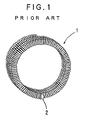
- FIG. 1 illustrates a conventional coiled body making up a coiled embolizing material.
- This coiled body 1 is a helical double-coiled body having deformability.
- a semi-spherical tip 2 is formed at one end thereof.
- the coiled body 1 Since the coiled body 1 has deformability, it shows a state that it is stretched in a substantially straight line along a catheter when it is pushed by a push-out means to move through the catheter, and returns to the original double-coiled body (the shape illustrated in FIG. 1) when it is pushed out of the catheter into an aneurysm, and the push-out means is detached from the coiled body.
- the outer diameter of the coiled body making up the embolizing material (for example, the outer diameter of the double-coiled body illustrated in FIG. 1) must be generally made somewhat greater than the inner diameter (the inner diameter when an internal space of the aneurysm is regarded as a sphere) of the aneurysm in which the coiled body should be deposited.
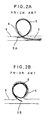
- a distal end portion 5A of a coiled body 5, which has been pushed out of a distal opening of a catheter 3 into an aneurysm 4, may extend out of the opening of the aneurysm 4 into a parental blood vessel 6 outside the dilatation.
- a proximal end portion 5B of the coiled body 5 deposited within the aneurysm 4 after a push-out means (not illustrated) is detached may extend out of the opening of the aneurysm 4 into the parental blood vessel 6 outside the dilatation.
- Such a state as described above particularly tends to occur when an aneurysm to be embolized has a slender form.
- thrombus is formed on the end portion of the coiled body extended out of the dilatation, and so the parental blood vessel is occluded by the thrombus, or the thrombus transmigrates to a peripheral vessel, thereby occluding such a peripheral vessel.
- the present invention has been completed under the foregoing circumstances. It is an object of the present invention to provide a coiled embolizing material, which can surely embolize an application site without extending either end portion thereof out into a vessel, for example, a parental blood vessel outside a dilatation, outside the application site.
- a coiled embolizing material to be deposited at an intended site in a vasculature, wherein at least one end portion of the embolizing material is curved inward in a radial direction of a coil thereof.
- the coiled embolizing material according to the present invention may comprise a double-coiled body, wherein at least one end portion of the double-coiled body is curved inward in a radial direction of a secondary coil thereof.
- a push-out means for the embolizing material may preferably be detachably connected to the embolizing material.
- the push-out means for the embolizing material may preferably be detachably connected to the embolizing material through a joint member.
- the joint member may preferably be formed of poly(vinyl alcohol) or a vinyl alcohol copolymer.
- the coiled embolizing material can be deposited at an application site in a state that it is fitted to the inner wall of the application site, and moreover the end portion of the coiled embolizing material can be prevented from extending out into a vessel outside the application site.
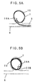
- the coiled embolizing material having the distal end portion curved inward moves along the inner wall of the application site in a state that the distal end thereof points to the interior of the dilatation. Therefore, the distal end portion of the embolizing material pushed out of the distal opening of, for example, a catheter into the aneurysm does not damage the inner wall surface of the aneurysm, and is surely present in the aneurysm, thereby preventing it from extending out of the dilatation into a parental blood vessel.
- the push-out means When the push-out means is detached from the coiled embolizing material introduced into the application site or dilatation, the coiled embolizing material having the proximal end portion curved inward returns to a state that the proximal end thereof points to the interior of the dilatation. Therefore, the proximal end portion of the embolizing material deposited into the aneurysm is surely present in the aneurysm, thereby preventing it from extending out of the dilatation into a parental blood vessel.
- FIGs. 2A and 2B schematically illustrate a state that an end portion of the coiled body of the conventional embolizing material, which has been introduced into an aneurysm, extends out into a parental blood vessel outside the dilatation.
- FIG. 4 illustrates another example of a coiled body making up a coiled embolizing material according to the present invention.
- FIGs. 5A and 5B schematically illustrate a state that an end portion or end portions of each coiled body of the embolizing materials according to the present invention, which each have been introduced into an aneurysm, are present in the application site.
- the coiled body 10 is a helical double-coiled body obtained by winding the above-described wire to form a primary coil and further winding the primary coil to form a secondary coil.
- a diameter of the primary coil is generally 0.1-1.0 mm, preferably 0.2-0.5 mm, while a diameter of the secondary coil is suitably selected according to the inner diameter of an application site, for example, aneurysm, but is generally 2-40 mm, preferably 2-20 mm.
- the curved portion or the distal end portion 10A of the coiled body 10 may have either the same curvature or an increasing curvature, for example, clothoid, toward the distal end.
- the curvature of the curved portion is preferably greater than that of the inner wall of the application site.
- the distal end portion 10A may be wound at least one turn along a circle of a diameter smaller than that of the secondary coil.
- the joint member 40 when a material having sufficiently high stiffness and mechanical strength at the temperature of the human body, and a melting point of 100 °C or lower is selected as a material for the joint member 40, the joint member 40 can be heated and severed within a short period of time by supplying the high-frequency current thereto. More specifically, when the joint member 40 is formed of poly(vinyl alcohol) or a vinyl alcohol copolymer, the joint member 40 can be melted and severed by supplying a high-frequency current for an extremely short period within 3 seconds, for example. Therefore, burdens imposed not only on a surgeon, but also on a patient to be operated can be very lightened. In addition, a possibility that contingencies may occur on the vital body during the depositing operation can be lessened to a great extent.
Applications Claiming Priority (3)
| Application Number | Priority Date | Filing Date | Title |
|---|---|---|---|
| JP215553/96 | 1996-08-15 | ||
| JP21555396A JP3784112B2 (ja) | 1996-08-15 | 1996-08-15 | コイル状塞栓物質 |
| JP21555396 | 1996-08-15 |
Publications (4)
| Publication Number | Publication Date |
|---|---|
| EP0824010A2 true EP0824010A2 (fr) | 1998-02-18 |
| EP0824010A3 EP0824010A3 (fr) | 1998-02-25 |
| EP0824010B1 EP0824010B1 (fr) | 2003-02-26 |
| EP0824010B2 EP0824010B2 (fr) | 2006-01-11 |
Family
ID=16674341
Family Applications (1)
| Application Number | Title | Priority Date | Filing Date |
|---|---|---|---|
| EP97113673A Expired - Lifetime EP0824010B2 (fr) | 1996-08-15 | 1997-08-07 | Bobine d'embolisation |
Country Status (4)
| Country | Link |
|---|---|
| US (1) | US5891058A (fr) |
| EP (1) | EP0824010B2 (fr) |
| JP (1) | JP3784112B2 (fr) |
| DE (1) | DE69719257T3 (fr) |
Cited By (1)
| Publication number | Priority date | Publication date | Assignee | Title |
|---|---|---|---|---|
| WO2000010469A1 (fr) * | 1998-08-25 | 2000-03-02 | Micrus Corporation | Enroulement pour occlusion vasculaire |
Families Citing this family (31)
| Publication number | Priority date | Publication date | Assignee | Title |
|---|---|---|---|---|
| US6984240B1 (en) | 1996-10-25 | 2006-01-10 | Target Therapeutics, Inc. | Detachable multidiameter vasoocclusive coil |
| US6113629A (en) * | 1998-05-01 | 2000-09-05 | Micrus Corporation | Hydrogel for the therapeutic treatment of aneurysms |
| EP1200012B1 (fr) | 1999-06-02 | 2007-11-07 | Sethel Interventional, Inc. | Dispositif d'occlusion intracorporel |
| US6355275B1 (en) | 2000-06-23 | 2002-03-12 | Carbon Medical Technologies, Inc. | Embolization using carbon coated microparticles |
| US6394965B1 (en) | 2000-08-15 | 2002-05-28 | Carbon Medical Technologies, Inc. | Tissue marking using biocompatible microparticles |
| US6605101B1 (en) * | 2000-09-26 | 2003-08-12 | Microvention, Inc. | Microcoil vaso-occlusive device with multi-axis secondary configuration |
| US7033374B2 (en) * | 2000-09-26 | 2006-04-25 | Microvention, Inc. | Microcoil vaso-occlusive device with multi-axis secondary configuration |
| US7029486B2 (en) * | 2000-09-26 | 2006-04-18 | Microvention, Inc. | Microcoil vaso-occlusive device with multi-axis secondary configuration |
| EP1381420A2 (fr) * | 2001-04-26 | 2004-01-21 | Christopher H. Porter | Procede et appareil d'administration corporelle de matieres |
| EP1448105B1 (fr) | 2001-11-07 | 2009-12-23 | Microvention, Inc. | Dispositif pour occlusion vasculaire a micro-enroulement ayant une configuration secondaire a axes multiples |
| US8845676B2 (en) | 2004-09-22 | 2014-09-30 | Micro Therapeutics | Micro-spiral implantation device |
| WO2006032289A1 (fr) | 2004-09-22 | 2006-03-30 | Dendron Gmbh | Implant medical |
| CA2585147A1 (fr) * | 2004-11-09 | 2006-05-18 | Boston Scientific Limited | Dispositifs vaso-occlusifs presentant une partie proximale de forme complexe et une partie distale a diametre inferieur |
| US8864790B2 (en) | 2006-04-17 | 2014-10-21 | Covidien Lp | System and method for mechanically positioning intravascular implants |
| US8777979B2 (en) | 2006-04-17 | 2014-07-15 | Covidien Lp | System and method for mechanically positioning intravascular implants |
| CN101677821B (zh) | 2007-03-13 | 2014-05-14 | 泰科保健集团有限合伙公司 | 植入物和轴柄 |
| JP5249249B2 (ja) | 2007-03-13 | 2013-07-31 | コヴィディエン リミテッド パートナーシップ | コイルと耐伸張性部材とが含まれているインプラント |
| EP2234562B1 (fr) | 2007-12-21 | 2019-02-27 | MicroVention, Inc. | Système et procédé de détection de détachement d'implant |
| EP2231030B1 (fr) | 2007-12-21 | 2019-02-27 | MicroVention, Inc. | Système et procédé permettant de localiser une zone de détachement d'un implant amovible |
| US8333796B2 (en) | 2008-07-15 | 2012-12-18 | Penumbra, Inc. | Embolic coil implant system and implantation method |
| WO2010134914A1 (fr) * | 2009-05-20 | 2010-11-25 | University Of Miami | Enroulements emboliques hélicoïdaux sphériques pour le traitement d'anévrismes cérébraux |
| US8911487B2 (en) | 2009-09-22 | 2014-12-16 | Penumbra, Inc. | Manual actuation system for deployment of implant |
| CA2795740C (fr) | 2010-04-14 | 2018-03-13 | Microvention, Inc. | Dispositif d'implantation d'implant |
| US9579104B2 (en) | 2011-11-30 | 2017-02-28 | Covidien Lp | Positioning and detaching implants |
| US9011480B2 (en) | 2012-01-20 | 2015-04-21 | Covidien Lp | Aneurysm treatment coils |
| US9687245B2 (en) | 2012-03-23 | 2017-06-27 | Covidien Lp | Occlusive devices and methods of use |
| US20140114255A1 (en) * | 2012-10-19 | 2014-04-24 | Cook Medical Technologies Llc | Self-coiling stylet needle device |
| JP6566961B2 (ja) | 2014-02-27 | 2019-08-28 | インキュメデックス インコーポレイテッド | 塞栓骨組マイクロコイル |
| US9713475B2 (en) | 2014-04-18 | 2017-07-25 | Covidien Lp | Embolic medical devices |
| US10307168B2 (en) | 2015-08-07 | 2019-06-04 | Terumo Corporation | Complex coil and manufacturing techniques |
| EP3755237B1 (fr) | 2018-02-20 | 2022-04-27 | Boston Scientific Scimed Inc. | Système de pose de dispositif médical |
Citations (15)
| Publication number | Priority date | Publication date | Assignee | Title |
|---|---|---|---|---|
| DE3203410A1 (de) * | 1981-05-08 | 1982-11-25 | VEB Kombinat Wälzlager und Normteile, DDR 9022 Karl-Marx-Stadt | Verschlusskoerper und verfahren zu seiner herstellung |
| US4994069A (en) * | 1988-11-02 | 1991-02-19 | Target Therapeutics | Vaso-occlusion coil and method |
| WO1991013592A1 (fr) * | 1990-03-13 | 1991-09-19 | The Regents Of The University Of California | Extremite de fil de guidage endovasculaire detachable de maniere electrolytique |
| US5217484A (en) * | 1991-06-07 | 1993-06-08 | Marks Michael P | Retractable-wire catheter device and method |
| EP0547530A1 (fr) * | 1991-12-16 | 1993-06-23 | HENRY FORD HEALTH SYSTEM, d/b/a HENRY FORD HOSPITAL | Implant à hydrogel intravasculaire |
| WO1993016650A1 (fr) * | 1992-02-24 | 1993-09-02 | Regents Of The University Of California | Fil endovasculaire detachable electrolytiquement et servant a la formation de thrombus |
| US5261916A (en) * | 1991-12-12 | 1993-11-16 | Target Therapeutics | Detachable pusher-vasoocclusive coil assembly with interlocking ball and keyway coupling |
| WO1994006503A1 (fr) * | 1992-09-22 | 1994-03-31 | Target Therapeutics, Inc. | Ensemble fil helicoidal embolique liberable |
| WO1995011055A1 (fr) * | 1993-10-22 | 1995-04-27 | Scimed Lifesystems, Inc. | Appareil et procede ameliores de mise en place d'extenseurs |
| WO1995012367A1 (fr) * | 1993-11-03 | 1995-05-11 | Target Therapeutics, Inc. | Jointure separable par voie electrolytique, pour dispositifs emboliques endovasculaires |
| JPH07265431A (ja) * | 1994-03-31 | 1995-10-17 | Kaneka Medics:Kk | 生体内留置部材を有する医療用ワイヤー |
| EP0719522A1 (fr) * | 1994-12-30 | 1996-07-03 | Target Therapeutics, Inc. | Joint sans soudure, détachable électrolytiquement, pour implanter des éléments séparables dans le corps |
| EP0739605A1 (fr) * | 1995-04-28 | 1996-10-30 | Target Therapeutics | Spirale embolique avec des formes d'hélices désaxées et brillées |
| EP0747014A1 (fr) * | 1995-06-06 | 1996-12-11 | Target Therapeutics, Inc. | Ressort spiral vaso-occlusif formé en plusieurs couches |
| US5649949A (en) * | 1996-03-14 | 1997-07-22 | Target Therapeutics, Inc. | Variable cross-section conical vasoocclusive coils |
Family Cites Families (5)
| Publication number | Priority date | Publication date | Assignee | Title |
|---|---|---|---|---|
| US4676249A (en) * | 1986-05-19 | 1987-06-30 | Cordis Corporation | Multi-mode guidewire |
| US4739768B2 (en) * | 1986-06-02 | 1995-10-24 | Target Therapeutics Inc | Catheter for guide-wire tracking |
| US4884579A (en) * | 1988-04-18 | 1989-12-05 | Target Therapeutics | Catheter guide wire |
| JPH06246004A (ja) * | 1993-02-26 | 1994-09-06 | Raifu Technol Kenkyusho | カテーテル |
| JPH07284534A (ja) * | 1994-04-15 | 1995-10-31 | Kato Hatsujo Kaisha Ltd | 管状器官の治療具 |
-
1996
- 1996-08-15 JP JP21555396A patent/JP3784112B2/ja not_active Expired - Lifetime
-
1997
- 1997-08-06 US US08/907,236 patent/US5891058A/en not_active Expired - Lifetime
- 1997-08-07 EP EP97113673A patent/EP0824010B2/fr not_active Expired - Lifetime
- 1997-08-07 DE DE69719257T patent/DE69719257T3/de not_active Expired - Lifetime
Patent Citations (16)
| Publication number | Priority date | Publication date | Assignee | Title |
|---|---|---|---|---|
| DE3203410A1 (de) * | 1981-05-08 | 1982-11-25 | VEB Kombinat Wälzlager und Normteile, DDR 9022 Karl-Marx-Stadt | Verschlusskoerper und verfahren zu seiner herstellung |
| US4994069A (en) * | 1988-11-02 | 1991-02-19 | Target Therapeutics | Vaso-occlusion coil and method |
| WO1991013592A1 (fr) * | 1990-03-13 | 1991-09-19 | The Regents Of The University Of California | Extremite de fil de guidage endovasculaire detachable de maniere electrolytique |
| US5217484A (en) * | 1991-06-07 | 1993-06-08 | Marks Michael P | Retractable-wire catheter device and method |
| US5261916A (en) * | 1991-12-12 | 1993-11-16 | Target Therapeutics | Detachable pusher-vasoocclusive coil assembly with interlocking ball and keyway coupling |
| EP0547530A1 (fr) * | 1991-12-16 | 1993-06-23 | HENRY FORD HEALTH SYSTEM, d/b/a HENRY FORD HOSPITAL | Implant à hydrogel intravasculaire |
| WO1993016650A1 (fr) * | 1992-02-24 | 1993-09-02 | Regents Of The University Of California | Fil endovasculaire detachable electrolytiquement et servant a la formation de thrombus |
| WO1994006503A1 (fr) * | 1992-09-22 | 1994-03-31 | Target Therapeutics, Inc. | Ensemble fil helicoidal embolique liberable |
| WO1995011055A1 (fr) * | 1993-10-22 | 1995-04-27 | Scimed Lifesystems, Inc. | Appareil et procede ameliores de mise en place d'extenseurs |
| WO1995012367A1 (fr) * | 1993-11-03 | 1995-05-11 | Target Therapeutics, Inc. | Jointure separable par voie electrolytique, pour dispositifs emboliques endovasculaires |
| JPH07265431A (ja) * | 1994-03-31 | 1995-10-17 | Kaneka Medics:Kk | 生体内留置部材を有する医療用ワイヤー |
| EP0719522A1 (fr) * | 1994-12-30 | 1996-07-03 | Target Therapeutics, Inc. | Joint sans soudure, détachable électrolytiquement, pour implanter des éléments séparables dans le corps |
| EP0739605A1 (fr) * | 1995-04-28 | 1996-10-30 | Target Therapeutics | Spirale embolique avec des formes d'hélices désaxées et brillées |
| EP0747014A1 (fr) * | 1995-06-06 | 1996-12-11 | Target Therapeutics, Inc. | Ressort spiral vaso-occlusif formé en plusieurs couches |
| US5649949A (en) * | 1996-03-14 | 1997-07-22 | Target Therapeutics, Inc. | Variable cross-section conical vasoocclusive coils |
| EP0795300A1 (fr) * | 1996-03-14 | 1997-09-17 | Target Therapeutics, Inc. | Ressort spiral vaso-occlusif conique à section variable |
Cited By (1)
| Publication number | Priority date | Publication date | Assignee | Title |
|---|---|---|---|---|
| WO2000010469A1 (fr) * | 1998-08-25 | 2000-03-02 | Micrus Corporation | Enroulement pour occlusion vasculaire |
Also Published As
| Publication number | Publication date |
|---|---|
| JP3784112B2 (ja) | 2006-06-07 |
| EP0824010B1 (fr) | 2003-02-26 |
| EP0824010B2 (fr) | 2006-01-11 |
| DE69719257D1 (de) | 2003-04-03 |
| JPH1057385A (ja) | 1998-03-03 |
| DE69719257T2 (de) | 2003-09-18 |
| EP0824010A3 (fr) | 1998-02-25 |
| US5891058A (en) | 1999-04-06 |
| DE69719257T3 (de) | 2006-11-02 |
Similar Documents
| Publication | Publication Date | Title |
|---|---|---|
| EP0824010B1 (fr) | Bobine d'embolisation | |
| US6743251B1 (en) | Implantable devices with polymeric detachment junction | |
| JP3557386B2 (ja) | 導電性体液内で体腔を閉塞するための電解分離可能なワイヤ先端部分 | |
| US6533801B2 (en) | Vaso-occlusive member assembly with multiple detaching points | |
| JP4106178B2 (ja) | 迅速取り外し電気絶縁インプラント | |
| US5891128A (en) | Solderless electrolytically severable joint for detachable devices placed within the mammalian body | |
| JP4127960B2 (ja) | 着脱可能な動脈瘤頸部ブリッジ | |
| US5759161A (en) | Medical wire and method for leaving implanted devices | |
| US6425893B1 (en) | Method and apparatus for fast electrolytic detachment of an implant | |
| EP0715502B1 (fr) | Ensemble spirale a sectionnement electrolytique et a point de separation mobile | |
| US20060036280A1 (en) | Systems and methods for severing occlusive elements from a delivery catheter |
Legal Events
| Date | Code | Title | Description |
|---|---|---|---|
| PUAI | Public reference made under article 153(3) epc to a published international application that has entered the european phase |
Free format text: ORIGINAL CODE: 0009012 |
|
| PUAL | Search report despatched |
Free format text: ORIGINAL CODE: 0009013 |
|
| AK | Designated contracting states |
Kind code of ref document: A2 Designated state(s): DE FR GB |
|
| AK | Designated contracting states |
Kind code of ref document: A3 Designated state(s): AT BE CH DE DK ES FI FR GB GR IE IT LI LU MC NL PT SE |
|
| 17P | Request for examination filed |
Effective date: 19980529 |
|
| AKX | Designation fees paid |
Free format text: DE FR GB |
|
| RBV | Designated contracting states (corrected) |
Designated state(s): DE FR GB |
|
| GRAG | Despatch of communication of intention to grant |
Free format text: ORIGINAL CODE: EPIDOS AGRA |
|
| 17Q | First examination report despatched |
Effective date: 20020422 |
|
| GRAG | Despatch of communication of intention to grant |
Free format text: ORIGINAL CODE: EPIDOS AGRA |
|
| GRAH | Despatch of communication of intention to grant a patent |
Free format text: ORIGINAL CODE: EPIDOS IGRA |
|
| GRAH | Despatch of communication of intention to grant a patent |
Free format text: ORIGINAL CODE: EPIDOS IGRA |
|
| GRAA | (expected) grant |
Free format text: ORIGINAL CODE: 0009210 |
|
| AK | Designated contracting states |
Designated state(s): DE FR GB |
|
| REG | Reference to a national code |
Ref country code: GB Ref legal event code: FG4D |
|
| REF | Corresponds to: |
Ref document number: 69719257 Country of ref document: DE Date of ref document: 20030403 Kind code of ref document: P |
|
| ET | Fr: translation filed | ||
| PLBQ | Unpublished change to opponent data |
Free format text: ORIGINAL CODE: EPIDOS OPPO |
|
| PLBI | Opposition filed |
Free format text: ORIGINAL CODE: 0009260 |
|
| PLAX | Notice of opposition and request to file observation + time limit sent |
Free format text: ORIGINAL CODE: EPIDOSNOBS2 |
|
| 26 | Opposition filed |
Opponent name: BOSTON SCIENTIFIC LTD. Effective date: 20031126 |
|
| PLBB | Reply of patent proprietor to notice(s) of opposition received |
Free format text: ORIGINAL CODE: EPIDOSNOBS3 |
|
| PUAH | Patent maintained in amended form |
Free format text: ORIGINAL CODE: 0009272 |
|
| STAA | Information on the status of an ep patent application or granted ep patent |
Free format text: STATUS: PATENT MAINTAINED AS AMENDED |
|
| 27A | Patent maintained in amended form |
Effective date: 20060111 |
|
| AK | Designated contracting states |
Kind code of ref document: B2 Designated state(s): DE FR GB |
|
| ET3 | Fr: translation filed ** decision concerning opposition | ||
| PLAB | Opposition data, opponent's data or that of the opponent's representative modified |
Free format text: ORIGINAL CODE: 0009299OPPO |
|
| REG | Reference to a national code |
Ref country code: FR Ref legal event code: CA Effective date: 20130301 |
|
| REG | Reference to a national code |
Ref country code: FR Ref legal event code: PLFP Year of fee payment: 20 |
|
| PGFP | Annual fee paid to national office [announced via postgrant information from national office to epo] |
Ref country code: DE Payment date: 20160826 Year of fee payment: 20 Ref country code: GB Payment date: 20160830 Year of fee payment: 20 |
|
| PGFP | Annual fee paid to national office [announced via postgrant information from national office to epo] |
Ref country code: FR Payment date: 20160825 Year of fee payment: 20 |
|
| REG | Reference to a national code |
Ref country code: DE Ref legal event code: R071 Ref document number: 69719257 Country of ref document: DE |
|
| REG | Reference to a national code |
Ref country code: GB Ref legal event code: PE20 Expiry date: 20170806 |
|
| PG25 | Lapsed in a contracting state [announced via postgrant information from national office to epo] |
Ref country code: GB Free format text: LAPSE BECAUSE OF EXPIRATION OF PROTECTION Effective date: 20170806 |