EP0823763A1 - Durchführungshülle - Google Patents
Durchführungshülle Download PDFInfo
- Publication number
- EP0823763A1 EP0823763A1 EP96112879A EP96112879A EP0823763A1 EP 0823763 A1 EP0823763 A1 EP 0823763A1 EP 96112879 A EP96112879 A EP 96112879A EP 96112879 A EP96112879 A EP 96112879A EP 0823763 A1 EP0823763 A1 EP 0823763A1
- Authority
- EP
- European Patent Office
- Prior art keywords
- grommet
- groove
- recess
- panel
- hollow body
- Prior art date
- Legal status (The legal status is an assumption and is not a legal conclusion. Google has not performed a legal analysis and makes no representation as to the accuracy of the status listed.)
- Granted
Links
Images


Classifications
-
- F—MECHANICAL ENGINEERING; LIGHTING; HEATING; WEAPONS; BLASTING
- F16—ENGINEERING ELEMENTS AND UNITS; GENERAL MEASURES FOR PRODUCING AND MAINTAINING EFFECTIVE FUNCTIONING OF MACHINES OR INSTALLATIONS; THERMAL INSULATION IN GENERAL
- F16L—PIPES; JOINTS OR FITTINGS FOR PIPES; SUPPORTS FOR PIPES, CABLES OR PROTECTIVE TUBING; MEANS FOR THERMAL INSULATION IN GENERAL
- F16L5/00—Devices for use where pipes, cables or protective tubing pass through walls or partitions
- F16L5/02—Sealing
- F16L5/10—Sealing by using sealing rings or sleeves only
-
- B—PERFORMING OPERATIONS; TRANSPORTING
- B60—VEHICLES IN GENERAL
- B60R—VEHICLES, VEHICLE FITTINGS, OR VEHICLE PARTS, NOT OTHERWISE PROVIDED FOR
- B60R16/00—Electric or fluid circuits specially adapted for vehicles and not otherwise provided for; Arrangement of elements of electric or fluid circuits specially adapted for vehicles and not otherwise provided for
- B60R16/02—Electric or fluid circuits specially adapted for vehicles and not otherwise provided for; Arrangement of elements of electric or fluid circuits specially adapted for vehicles and not otherwise provided for electric constitutive elements
- B60R16/0207—Wire harnesses
- B60R16/0215—Protecting, fastening and routing means therefor
- B60R16/0222—Grommets
-
- F—MECHANICAL ENGINEERING; LIGHTING; HEATING; WEAPONS; BLASTING
- F16—ENGINEERING ELEMENTS AND UNITS; GENERAL MEASURES FOR PRODUCING AND MAINTAINING EFFECTIVE FUNCTIONING OF MACHINES OR INSTALLATIONS; THERMAL INSULATION IN GENERAL
- F16L—PIPES; JOINTS OR FITTINGS FOR PIPES; SUPPORTS FOR PIPES, CABLES OR PROTECTIVE TUBING; MEANS FOR THERMAL INSULATION IN GENERAL
- F16L41/00—Branching pipes; Joining pipes to walls
- F16L41/08—Joining pipes to walls or pipes, the joined pipe axis being perpendicular to the plane of the wall or to the axis of another pipe
- F16L41/088—Joining pipes to walls or pipes, the joined pipe axis being perpendicular to the plane of the wall or to the axis of another pipe fixed using an elastic grommet between the extremity of the tube and the wall
Definitions
- the present invention relates to a grommet for sealing an opening in a panel through which at least one cable passes and, more particularly to a grommet used in the automotive industry for sealing an opening in a panel separating the engine compartment from the passenger compartment against water, heat and dirts, through which panel at least one cable or wiring harness passes.
- grommets There are generally known three types of grommets. From the USP No. 3424857, a grommet is known which is plugged into the opening so as to deform a tapered front body portion for allowing the engagement of the panel in a groove provided therefor. This type of grommet is either fully formed of rubber or is filled after insertion with a reinforcement material, e.g. cement.
- a second known grommet consists of two portions which are joined via the opening in the panel through which the cable passes and which is to be sealed.
- Such a grommet is known from the USP No. 4839937. The two parts of this grommet are placed on the opposite sides of the panel.
- a third type of grommet is known from the JP-A-108122/1988.
- This type of grommet comprises a tapered hollow body which is provided with a groove for the engagement with the edge of the opening in the panel.
- From the JP-A-108122/1988 there is further known to provide a recess in the groove or in the front face of the grommet in order to provide a groove with a self-adjusting width.
- the subject matter of the present invention is directed to the last type of grommet.
- the grommet For mounting the known grommet into the panel, the grommet is usually deformed, and then urged by hand through the opening (first step). Afterwards, the grommet is pulled at the tapered end until the engagement between the groove and the panel is obtained (second step).
- the operator is required to use his both hands to deform the grommet so as to pass it through the opening and to pull the grommet backward to deform the main body thereof so that the grommet engages the panel.
- the grommet for sealing an opening in a panel through which at least one cable passes comprises a tapered hollow body which sealingly engages the cable at least at a first end and the edge of the opening via a groove formed on a second end.
- On an inner surface and/or on an outer surface of the hollow body of the grommet means for reducing stiffness is provided.
- the means for reducing stiffness is preferably formed by a recess.
- the means for reducing stiffness is provided such that the elastic deformation of the grommet, in particular of its second end having a larger diameter than the first end is facilitated.
- the grommet is preferably formed unitarily of rubber by molding, and is formed by comolding if several materials are used in combination.
- the grommet, in particular the second end portion and/or the tapered portion are more easily deformable.
- easier deformation ensures easier insertion of the grommet through the opening in the panel during the first operation step.
- the main body thereof when the grommet is pulled backward to be engaged with the panel, the main body thereof can be deformed by the radial pressure applied by the edge of the opening when an axial force is applied to the grommet.
- the easier deformation largely reduces the required axial force for pulling the grommet until the snap engagement of the groove with the panel, thereby enabling this action to be performed solely by one hand.
- a grommet is provided which can be mounted even if only a restricted space is available.
- the means for reducing stiffness is provided on a radially inner or radially outer surface of the hollow body or formed as recesses the radial depths of which might correspond approximately to the half of the material thickness without the recess.
- a recess is provided behind the groove when seen in the axial direction from the second end.
- the void area of the recess can accommodate or receive the material of the hollow body that is deformed by the radial force applied to the hollow body by the edge of the opening in the panel upon actual thrust on the grommet.
- a recess be provided before the groove when seen in the axial direction from the second end.
- the second end in form of a flange is more easily deformable, which specifically helps when deforming the grommet in order to allow the inserted end to pass through the opening in the panel.
- a recess is provided at a location substantially within the area of the bottom of the groove, wherein the width of the recess is preferably smaller than the width of the groove.
- a plurality of means for reducing stiffness can be provided on the same grommet. Any combination of the aforementioned recesses can be used in order to achieve a desired flexibility while the elastic restoring force of the grommet is maintained at a level which is sufficient to securely engage the panel via the groove.
- the means for reducing stiffness may be directly formed during the production of the grommet. Specifically, this means is formed by providing projections in the mold in order to form recesses on the inner and/or outer radial surface of the hollow body.
- the means for reducing stiffness, in particular recesses may be formed after the production of the grommet by removal of material by suitable means such as blades, heat treatment or the like.
- the recess or recesses extend over the entire circumference of the hollow body so that no specific orientation of the grommet is necessary when the grommet is mounted to the panel. However, on some occasions, webbing may be provided to enhance the stiffness of localized areas of the grommet if required.
- the means for reducing stiffness comprises preferably a more flexible or elastic material, which is most preferably comolded with the rubber material of the grommet in order to enhance productivity.
- the groove of the grommet have the largest width at the bottom thereof.
- the groove have a substantially triangular or L-shaped cross section in order to optimally receive a flange of the panel portion therein, which is usually L-shaped in the automotive industry.
- the groove can obviously have other forms which conform to the form of the edge of the panel, in which an opening is formed.
- the edges of the groove are preferably provided as sealing lips.
- a determinable sealing function can be achieved.
- the elastic restoring force of the grommet, acting as a line pressure at the sealing lip provides better protection against intrusion of fluid and dirts.
- fluid film formation is avoided by the use of the sealing lips.
- further sealing lips can be provided along the groove, wherein mating recesses can also be formed in the panel to obtain an even better engagement.
- a radial projection which serve as a sealing lip may preferably be provided at the bottom of the groove, wherein the recess, if provided at a location substantially within the area of the bottom of the groove, is preferably offset with respect to that projection such that the reduced stiffness does not impair the action of the sealing lip.
- the tapered portion of the grommet at least adjacent to the groove of the hollow body is preferably formed of a more elastic material and/or in a wave form so that this portion is more easily deformable.
- This preferred feature is specifically directed to the second step of operation, i.e. the pulling of the grommet for deforming the tapered portion until the engagement of the groove with the edge of the panel is achieved.
- the grommet may include more elastic material than rubber.
- the invention relates also to the use of the above defined grommet for sealingly passing a wiring harness through a panel and, particularly to the use of a grommet in the automotive industry, where such a grommet is usable for sealingly passing a wiring harness through a panel which separates the engine compartment from the passenger compartment.
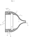
- a grommet for sealing an opening in a panel through which at least one cable passes includes a unitary tapered hollow body formed of rubber or any other suitable flexible and elastically deformable material.
- the grommet 1 has one first tapered end 10 which is provided for sealingly receiving or engaging the cable or wiring harness.
- a tapered body portion which is defined by an inner surface 5 and an outer surface 6 extends.
- a groove 30 is formed at the end, having a larger diameter, of the tapered portion.
- the groove 30 has, in the shown embodiment, two outer edges 34, 36 which provide a line contact with an unillustrated panel inserted into the groove 30.
- the edges 34, 36 are formed as sealing lips.
- the cross section of the groove 30 corresponds essentially to a trapezoid, most specifically to such a trapezoidal form having a right angle.
- the groove 30 has the largest width at the bottom thereof.
- a radial projection 32 which serves as a sealing lip when engaging the edge of the panel inserted into the groove 30.
- a flange-like or disk-like second end 20 is provided adjacent to the groove 30.
- a recess 12 is formed behind the groove 30 when seen in the axial direction from the second end 20. In this embodiment, the recess 12 extends substantially over the entire circumference of the inner surface 5 of the grommet 1.
- the width and depth of the recess 12 are chosen such that a desired amount of material forming the grommet 1 can be received therein upon deformation.
- the width and depth of the recess 12 correspond essentially to the half of the wall thickness of the grommet 1 at the location adjacent to the recess 12.
- FIG. 2 The basic construction of a grommet shown in FIG. 2 is similar to that of the grommet 1 shown in FIG. 1 except in the point that a recess 14 is formed at a location substantially within the area of the bottom of the groove 30.
- the recess 14 extends over the entire circumference of the inner surface 5 of the grommet 1.
- the recess 14 is displaced with respect to the radial projection 32 such that the elastically restoring force of the grommet acting on the radial projection 32 is not impaired.
- a recess 16 is provided adjacent to the second end 20 of the grommet 1 and before the groove 30 when seen in the axial direction from the second end 20.
- the width and depth of the recess 16 which extends over the entire circumference of the inner surface 5 of the grommet 1 are about 25% of the material thickness adjacent to the recess 16.
- the recess 16 particularly facilitates deformation of the second end portion of the grommet 1, facilitating the first step of the mounting operation of the grommet 1, e.g. the insertion of the grommet into the opening.
- FIG. 4 shows a particularly preferred grommet having a recess 12 of polygonal cross section and a recess 14 of a semi-circular cross section.
- the recess 12 has a depth approximately 1.5 times the depth of the recess 14.
- the depth of the recess 14 corresponds approximately to 1/3 to 1/2 of the material thickness at the location of the groove 30.
- the recess 14 is distanced from the groove 30 such that a portion of the grommet 1 connecting the recess 14 and the groove 30 has a sufficient strength.
- the recess 14 is, similar to the embodiment shown in FIG. 2, offset with respect to the sealing lip 32.
- the second end 20 has an appreciably large diameter in order to securely engage the edge of the unillustrated panel.
- the side walls of the groove 30 are slightly slanted toward each other in order to provide the line contact with the panel to be engaged.
- One outer edge 34 of the groove 30 projects inwardly of the groove 30, thereby forming a sealing lip.
- the recesses 12, 14 extend over the entire circumference of the inner surface 5.
- FIG. 5 shows one preferred embodiment comprising the three recesses of FIGS. 1 to 3 in combination. It should be noted that only one or two recesses or more than 3 recesses may be provided in combination. All or some of the recesses shown in the embodiments of FIGS. 1 to 5 could also be located on the outer surface 6 of the grommet.
- the form of the recesses is not limited to the one shown in the foregoing embodiments, but may also be rectangular or triangular.
- FIG. 6 shows a further preferred embodiment of the inventive grommet.
- the structure of the grommet is very similar to the one shown in FIG. 1.
- means for reducing stiffness is formed by a recess which is filled at least partially with a softer material than the rubber forming the grommet.
- a softer or more easily deformable material substantially the same effects as by providing recesses according to the previous embodiments can be obtained.
- a softer or more elastic material can also be used to at least partially form the tapered portion of the grommet. Though unillustrated, the tapered portion may have a corrugated form so that it is more easily deformable.
- inventive grommet may have any suitable cross sectional form, e.g. a round, rectangular, or elliptical form.
- the inventive grommet facilitates the sealing of an opening in the panel through which at least one cable passes, in particular under restricted space conditions.
- the operator only needs one hand and substantially reduced effort.
Landscapes
- Engineering & Computer Science (AREA)
- General Engineering & Computer Science (AREA)
- Mechanical Engineering (AREA)
- Installation Of Indoor Wiring (AREA)
- Insulating Bodies (AREA)
Priority Applications (3)
| Application Number | Priority Date | Filing Date | Title |
|---|---|---|---|
| US08/695,859 US5701634A (en) | 1996-08-09 | 1996-08-09 | Grommet |
| EP96112879A EP0823763B1 (de) | 1996-08-09 | 1996-08-09 | Durchführungshülle |
| DE1996605033 DE69605033T2 (de) | 1996-08-09 | 1996-08-09 | Durchführungshülle |
Applications Claiming Priority (2)
| Application Number | Priority Date | Filing Date | Title |
|---|---|---|---|
| US08/695,859 US5701634A (en) | 1996-08-09 | 1996-08-09 | Grommet |
| EP96112879A EP0823763B1 (de) | 1996-08-09 | 1996-08-09 | Durchführungshülle |
Publications (2)
| Publication Number | Publication Date |
|---|---|
| EP0823763A1 true EP0823763A1 (de) | 1998-02-11 |
| EP0823763B1 EP0823763B1 (de) | 1999-11-03 |
Family
ID=26142126
Family Applications (1)
| Application Number | Title | Priority Date | Filing Date |
|---|---|---|---|
| EP96112879A Expired - Lifetime EP0823763B1 (de) | 1996-08-09 | 1996-08-09 | Durchführungshülle |
Country Status (2)
| Country | Link |
|---|---|
| US (1) | US5701634A (de) |
| EP (1) | EP0823763B1 (de) |
Cited By (3)
| Publication number | Priority date | Publication date | Assignee | Title |
|---|---|---|---|---|
| DE102005019416B4 (de) * | 2004-04-30 | 2016-05-19 | Icotek Project Gmbh & Co. Kg | Kabeldurchführung |
| WO2022033776A1 (de) * | 2020-08-13 | 2022-02-17 | Auto-Kabel Management Gmbh | Dichtung für ein elektrisches kabel |
| DE102004055103B4 (de) | 2003-11-18 | 2022-05-12 | Icotek Project Gmbh & Co. Kg | Vorrichtung zur Durchführung von Kabeln durch Wände |
Families Citing this family (18)
| Publication number | Priority date | Publication date | Assignee | Title |
|---|---|---|---|---|
| DE29609416U1 (de) * | 1996-05-25 | 1996-08-14 | Alcatel Kabel AG & Co., 30179 Hannover | Vorrichtung zur Durchführung eines langgestreckten Gegenstandes durch eine Öffnung einer Wand |
| US6583356B2 (en) | 1998-02-19 | 2003-06-24 | Walker Systems, Inc. | Wire protection grommet for high-speed communications cabling |
| PL342258A1 (en) | 1998-02-19 | 2001-06-04 | Walker Systems | Cable bushing for protecting a cable while pulling it through a cable passage opening |
| US6088876A (en) * | 1998-09-30 | 2000-07-18 | Lucent Technologies, Inc. | Sealing grommet |
| JP3520797B2 (ja) * | 1999-03-02 | 2004-04-19 | 住友電装株式会社 | グロメット |
| FR2823609B1 (fr) * | 2001-04-12 | 2003-05-30 | Nexans | Joint d'etancheite pour cables |
| DE10225164A1 (de) * | 2002-06-06 | 2003-12-18 | Volkswagen Ag | Tülle für Leitungsdurchführungen |
| DE102004018816A1 (de) * | 2004-04-19 | 2005-11-03 | E. Missel Gmbh & Co. Kg | Dichtelement |
| US7244085B2 (en) * | 2004-04-26 | 2007-07-17 | Illinois Tool Works, Inc | Fastener assembly |
| DE202004015861U1 (de) * | 2004-10-13 | 2006-03-16 | Liebherr-Hausgeräte Ochsenhausen GmbH | Dichtelement |
| US20090108146A1 (en) * | 2007-10-31 | 2009-04-30 | Svette Jr Joseph A | Low ergonomic grommet and method of making |
| US8944718B2 (en) | 2010-09-23 | 2015-02-03 | C-Flex Bearing Co., Inc. | Clamping bushing |
| JP6424793B2 (ja) * | 2015-10-19 | 2018-11-21 | 住友電装株式会社 | グロメットおよびワイヤハーネス |
| US20190056044A1 (en) * | 2015-12-03 | 2019-02-21 | Mitsubishi Electric Corporation | Elastic body for closure, air conditioning device, and closure method |
| EP3279537A1 (de) * | 2016-08-04 | 2018-02-07 | ATOTECH Deutschland GmbH | Flexibles dichtungselement |
| US10378752B1 (en) * | 2016-09-08 | 2019-08-13 | Eaton Intelligent Power Limited | Integrated gasket for utility light fixtures |
| CA3096050A1 (en) | 2018-04-04 | 2019-10-10 | Corning Research & Development Corporation | Variable size seal and method |
| JP7216690B2 (ja) * | 2020-09-24 | 2023-02-01 | 矢崎総業株式会社 | グロメット、及び、ワイヤハーネス |
Citations (7)
| Publication number | Priority date | Publication date | Assignee | Title |
|---|---|---|---|---|
| US2897533A (en) * | 1956-02-16 | 1959-08-04 | Gen Motors Corp | Grommets, bushings and the like |
| US3424857A (en) | 1967-06-06 | 1969-01-28 | Lyall Electric | Grommet |
| FR2402323A1 (fr) * | 1977-09-02 | 1979-03-30 | Sarel | Dispositif d'obturation d'une ouverture formee dans une paroi, en particulier d'un boitier d'interrupteur, d'une boite de derivation, formant un capuchon rapporte sur ladite paroi |
| JPS63108122A (ja) | 1986-10-23 | 1988-05-13 | Yukio Sawara | 電子レンジ用オ−ブン調理具 |
| US4797513A (en) * | 1987-11-25 | 1989-01-10 | Yazaki Corporation | Grommet with wires sealed thereto and method of forming same |
| US4839937A (en) | 1987-07-15 | 1989-06-20 | Yazaki Corporation | Grommet structure |
| US5388915A (en) * | 1992-05-13 | 1995-02-14 | Bavaria Cargo Technologie Gmbh | Bearing bush |
Family Cites Families (6)
| Publication number | Priority date | Publication date | Assignee | Title |
|---|---|---|---|---|
| US2225472A (en) * | 1940-01-27 | 1940-12-17 | Albert W Franklin | Bushing |
| US2375373A (en) * | 1943-08-27 | 1945-05-08 | Quadrex Corp | Strain relief for electric cords |
| US2707723A (en) * | 1954-06-21 | 1955-05-03 | Walter H Moorhead | Self-locking flexible grommet |
| US3099057A (en) * | 1961-07-24 | 1963-07-30 | Boeing Co | Self-retaining fasteners |
| US4487998A (en) * | 1983-07-27 | 1984-12-11 | Amp Incorporated | Releasable grommet |
| US5453579A (en) * | 1991-06-27 | 1995-09-26 | Paccar Inc. | Combination grommet and water trap |
-
1996
- 1996-08-09 US US08/695,859 patent/US5701634A/en not_active Expired - Lifetime
- 1996-08-09 EP EP96112879A patent/EP0823763B1/de not_active Expired - Lifetime
Patent Citations (7)
| Publication number | Priority date | Publication date | Assignee | Title |
|---|---|---|---|---|
| US2897533A (en) * | 1956-02-16 | 1959-08-04 | Gen Motors Corp | Grommets, bushings and the like |
| US3424857A (en) | 1967-06-06 | 1969-01-28 | Lyall Electric | Grommet |
| FR2402323A1 (fr) * | 1977-09-02 | 1979-03-30 | Sarel | Dispositif d'obturation d'une ouverture formee dans une paroi, en particulier d'un boitier d'interrupteur, d'une boite de derivation, formant un capuchon rapporte sur ladite paroi |
| JPS63108122A (ja) | 1986-10-23 | 1988-05-13 | Yukio Sawara | 電子レンジ用オ−ブン調理具 |
| US4839937A (en) | 1987-07-15 | 1989-06-20 | Yazaki Corporation | Grommet structure |
| US4797513A (en) * | 1987-11-25 | 1989-01-10 | Yazaki Corporation | Grommet with wires sealed thereto and method of forming same |
| US5388915A (en) * | 1992-05-13 | 1995-02-14 | Bavaria Cargo Technologie Gmbh | Bearing bush |
Cited By (4)
| Publication number | Priority date | Publication date | Assignee | Title |
|---|---|---|---|---|
| DE102004055103B4 (de) | 2003-11-18 | 2022-05-12 | Icotek Project Gmbh & Co. Kg | Vorrichtung zur Durchführung von Kabeln durch Wände |
| DE102005019416B4 (de) * | 2004-04-30 | 2016-05-19 | Icotek Project Gmbh & Co. Kg | Kabeldurchführung |
| WO2022033776A1 (de) * | 2020-08-13 | 2022-02-17 | Auto-Kabel Management Gmbh | Dichtung für ein elektrisches kabel |
| US11881331B2 (en) | 2020-08-13 | 2024-01-23 | Auto-Kabel Management Gmbh | Gasket for an electric cable |
Also Published As
| Publication number | Publication date |
|---|---|
| EP0823763B1 (de) | 1999-11-03 |
| US5701634A (en) | 1997-12-30 |
Similar Documents
| Publication | Publication Date | Title |
|---|---|---|
| EP0823763A1 (de) | Durchführungshülle | |
| EP1193435B1 (de) | Dichtungstülle | |
| EP0677894B1 (de) | Abdichtungsvorrichtung und Herstellverfahren eines wasserdichten Stecker | |
| EP1424245B1 (de) | Manschette für ein Kabelstrang | |
| EP0731000B1 (de) | Durchführungstülle | |
| US6685195B2 (en) | Grommet | |
| US5774934A (en) | Grommet and a method for mounting a grommet | |
| US6353185B1 (en) | Grommet and method of installing said grommet on a panel | |
| US6722660B2 (en) | Molded gasket | |
| US5799442A (en) | Door glass weather strip | |
| US6465740B2 (en) | Grommet and method for fixing said grommet to a panel | |
| EP1125797A3 (de) | Büchse | |
| GB2289104A (en) | Grommet | |
| US6752655B1 (en) | Method and structure for fixing a locking connector to a vehicle member | |
| CN110884446A (zh) | 护环 | |
| US5138117A (en) | Watertight sealing lip for grommet | |
| US20040069521A1 (en) | Wire pass through seal with grommets | |
| EP0855765A2 (de) | Wasserdichter Verbinder | |
| US6279983B1 (en) | Method of installing automotive window molding | |
| JP2937038B2 (ja) | グロメット | |
| US20010040348A1 (en) | Pipe connecting gaskets | |
| JPH0532693Y2 (de) | ||
| JPH1092244A (ja) | グロメット | |
| GB2272470A (en) | Sealing strip for edge flange | |
| JP3794607B2 (ja) | グロメット |
Legal Events
| Date | Code | Title | Description |
|---|---|---|---|
| PUAI | Public reference made under article 153(3) epc to a published international application that has entered the european phase |
Free format text: ORIGINAL CODE: 0009012 |
|
| 17P | Request for examination filed |
Effective date: 19970206 |
|
| AK | Designated contracting states |
Kind code of ref document: A1 Designated state(s): DE FR GB |
|
| AKX | Designation fees paid |
Free format text: DE FR GB |
|
| RBV | Designated contracting states (corrected) |
Designated state(s): DE FR GB |
|
| 17Q | First examination report despatched |
Effective date: 19980703 |
|
| GRAG | Despatch of communication of intention to grant |
Free format text: ORIGINAL CODE: EPIDOS AGRA |
|
| GRAG | Despatch of communication of intention to grant |
Free format text: ORIGINAL CODE: EPIDOS AGRA |
|
| GRAH | Despatch of communication of intention to grant a patent |
Free format text: ORIGINAL CODE: EPIDOS IGRA |
|
| GRAH | Despatch of communication of intention to grant a patent |
Free format text: ORIGINAL CODE: EPIDOS IGRA |
|
| GRAA | (expected) grant |
Free format text: ORIGINAL CODE: 0009210 |
|
| AK | Designated contracting states |
Kind code of ref document: B1 Designated state(s): DE FR GB |
|
| REF | Corresponds to: |
Ref document number: 69605033 Country of ref document: DE Date of ref document: 19991209 |
|
| ET | Fr: translation filed | ||
| PLBE | No opposition filed within time limit |
Free format text: ORIGINAL CODE: 0009261 |
|
| STAA | Information on the status of an ep patent application or granted ep patent |
Free format text: STATUS: NO OPPOSITION FILED WITHIN TIME LIMIT |
|
| 26N | No opposition filed | ||
| REG | Reference to a national code |
Ref country code: GB Ref legal event code: IF02 |
|
| PGFP | Annual fee paid to national office [announced via postgrant information from national office to epo] |
Ref country code: GB Payment date: 20120808 Year of fee payment: 17 |
|
| PGFP | Annual fee paid to national office [announced via postgrant information from national office to epo] |
Ref country code: DE Payment date: 20120731 Year of fee payment: 17 Ref country code: FR Payment date: 20120823 Year of fee payment: 17 |
|
| GBPC | Gb: european patent ceased through non-payment of renewal fee |
Effective date: 20130809 |
|
| PG25 | Lapsed in a contracting state [announced via postgrant information from national office to epo] |
Ref country code: DE Free format text: LAPSE BECAUSE OF NON-PAYMENT OF DUE FEES Effective date: 20140301 |
|
| REG | Reference to a national code |
Ref country code: FR Ref legal event code: ST Effective date: 20140430 |
|
| REG | Reference to a national code |
Ref country code: DE Ref legal event code: R119 Ref document number: 69605033 Country of ref document: DE Effective date: 20140301 |
|
| PG25 | Lapsed in a contracting state [announced via postgrant information from national office to epo] |
Ref country code: GB Free format text: LAPSE BECAUSE OF NON-PAYMENT OF DUE FEES Effective date: 20130809 |
|
| PG25 | Lapsed in a contracting state [announced via postgrant information from national office to epo] |
Ref country code: FR Free format text: LAPSE BECAUSE OF NON-PAYMENT OF DUE FEES Effective date: 20130902 |