EP0823738A2 - Inertial positioner - Google Patents
Inertial positioner Download PDFInfo
- Publication number
- EP0823738A2 EP0823738A2 EP97112450A EP97112450A EP0823738A2 EP 0823738 A2 EP0823738 A2 EP 0823738A2 EP 97112450 A EP97112450 A EP 97112450A EP 97112450 A EP97112450 A EP 97112450A EP 0823738 A2 EP0823738 A2 EP 0823738A2
- Authority
- EP
- European Patent Office
- Prior art keywords
- rod
- carriage
- base
- positioner
- piezoelectric element
- Prior art date
- Legal status (The legal status is an assumption and is not a legal conclusion. Google has not performed a legal analysis and makes no representation as to the accuracy of the status listed.)
- Granted
Links
- 230000033001 locomotion Effects 0.000 claims abstract description 45
- 230000000737 periodic effect Effects 0.000 abstract 1
- 239000000463 material Substances 0.000 description 23
- 238000012360 testing method Methods 0.000 description 15
- 238000013461 design Methods 0.000 description 11
- 230000000694 effects Effects 0.000 description 7
- 230000000630 rising effect Effects 0.000 description 7
- 229910001220 stainless steel Inorganic materials 0.000 description 7
- 239000010935 stainless steel Substances 0.000 description 7
- WFKWXMTUELFFGS-UHFFFAOYSA-N tungsten Chemical compound [W] WFKWXMTUELFFGS-UHFFFAOYSA-N 0.000 description 7
- 229910052721 tungsten Inorganic materials 0.000 description 7
- 239000010937 tungsten Substances 0.000 description 7
- 230000006835 compression Effects 0.000 description 6
- 238000007906 compression Methods 0.000 description 6
- 230000008901 benefit Effects 0.000 description 4
- 230000008859 change Effects 0.000 description 4
- 239000007787 solid Substances 0.000 description 4
- 229910001369 Brass Inorganic materials 0.000 description 3
- 239000010951 brass Substances 0.000 description 3
- 239000000919 ceramic Substances 0.000 description 3
- 239000013078 crystal Substances 0.000 description 3
- 230000007423 decrease Effects 0.000 description 3
- 238000005259 measurement Methods 0.000 description 3
- 239000010453 quartz Substances 0.000 description 3
- 230000004044 response Effects 0.000 description 3
- VYPSYNLAJGMNEJ-UHFFFAOYSA-N silicon dioxide Inorganic materials O=[Si]=O VYPSYNLAJGMNEJ-UHFFFAOYSA-N 0.000 description 3
- 230000003068 static effect Effects 0.000 description 3
- IJGRMHOSHXDMSA-UHFFFAOYSA-N Atomic nitrogen Chemical compound N#N IJGRMHOSHXDMSA-UHFFFAOYSA-N 0.000 description 2
- XEEYBQQBJWHFJM-UHFFFAOYSA-N Iron Chemical compound [Fe] XEEYBQQBJWHFJM-UHFFFAOYSA-N 0.000 description 2
- 229910000831 Steel Inorganic materials 0.000 description 2
- RTAQQCXQSZGOHL-UHFFFAOYSA-N Titanium Chemical compound [Ti] RTAQQCXQSZGOHL-UHFFFAOYSA-N 0.000 description 2
- 230000001133 acceleration Effects 0.000 description 2
- 239000004411 aluminium Substances 0.000 description 2
- 229910052782 aluminium Inorganic materials 0.000 description 2
- XAGFODPZIPBFFR-UHFFFAOYSA-N aluminium Chemical compound [Al] XAGFODPZIPBFFR-UHFFFAOYSA-N 0.000 description 2
- 238000004458 analytical method Methods 0.000 description 2
- KUNSUQLRTQLHQQ-UHFFFAOYSA-N copper tin Chemical compound [Cu].[Sn] KUNSUQLRTQLHQQ-UHFFFAOYSA-N 0.000 description 2
- 239000010432 diamond Substances 0.000 description 2
- 238000006073 displacement reaction Methods 0.000 description 2
- 239000003822 epoxy resin Substances 0.000 description 2
- 230000005484 gravity Effects 0.000 description 2
- 229910052751 metal Inorganic materials 0.000 description 2
- 239000002184 metal Substances 0.000 description 2
- 230000005405 multipole Effects 0.000 description 2
- 230000003287 optical effect Effects 0.000 description 2
- 238000005498 polishing Methods 0.000 description 2
- 229920000647 polyepoxide Polymers 0.000 description 2
- 230000036316 preload Effects 0.000 description 2
- 230000009467 reduction Effects 0.000 description 2
- 230000035945 sensitivity Effects 0.000 description 2
- 239000010959 steel Substances 0.000 description 2
- 230000009897 systematic effect Effects 0.000 description 2
- 239000010936 titanium Substances 0.000 description 2
- 229910052719 titanium Inorganic materials 0.000 description 2
- 229910000906 Bronze Inorganic materials 0.000 description 1
- OAICVXFJPJFONN-UHFFFAOYSA-N Phosphorus Chemical compound [P] OAICVXFJPJFONN-UHFFFAOYSA-N 0.000 description 1
- 230000000712 assembly Effects 0.000 description 1
- 238000000429 assembly Methods 0.000 description 1
- 230000005540 biological transmission Effects 0.000 description 1
- 239000010974 bronze Substances 0.000 description 1
- 239000003990 capacitor Substances 0.000 description 1
- 229910010293 ceramic material Inorganic materials 0.000 description 1
- 238000006243 chemical reaction Methods 0.000 description 1
- 238000010276 construction Methods 0.000 description 1
- 238000007599 discharging Methods 0.000 description 1
- 238000005265 energy consumption Methods 0.000 description 1
- 230000005669 field effect Effects 0.000 description 1
- 239000011521 glass Substances 0.000 description 1
- 239000001307 helium Substances 0.000 description 1
- 229910052734 helium Inorganic materials 0.000 description 1
- SWQJXJOGLNCZEY-UHFFFAOYSA-N helium atom Chemical compound [He] SWQJXJOGLNCZEY-UHFFFAOYSA-N 0.000 description 1
- 230000003993 interaction Effects 0.000 description 1
- 229910052742 iron Inorganic materials 0.000 description 1
- 239000007788 liquid Substances 0.000 description 1
- 239000000314 lubricant Substances 0.000 description 1
- 238000003754 machining Methods 0.000 description 1
- 238000004519 manufacturing process Methods 0.000 description 1
- 150000002739 metals Chemical class 0.000 description 1
- 238000000034 method Methods 0.000 description 1
- 238000000386 microscopy Methods 0.000 description 1
- 229910052757 nitrogen Inorganic materials 0.000 description 1
- 230000009972 noncorrosive effect Effects 0.000 description 1
- 238000000399 optical microscopy Methods 0.000 description 1
- 239000004033 plastic Substances 0.000 description 1
- 238000012552 review Methods 0.000 description 1
- 239000010979 ruby Substances 0.000 description 1
- 229910001750 ruby Inorganic materials 0.000 description 1
- 239000000523 sample Substances 0.000 description 1
- 229910052594 sapphire Inorganic materials 0.000 description 1
- 239000010980 sapphire Substances 0.000 description 1
- 238000004621 scanning probe microscopy Methods 0.000 description 1
- 239000004065 semiconductor Substances 0.000 description 1
- 238000004611 spectroscopical analysis Methods 0.000 description 1
- 238000010561 standard procedure Methods 0.000 description 1
- 239000000758 substrate Substances 0.000 description 1
- PTISTKLWEJDJID-UHFFFAOYSA-N sulfanylidenemolybdenum Chemical compound [Mo]=S PTISTKLWEJDJID-UHFFFAOYSA-N 0.000 description 1
- 230000002123 temporal effect Effects 0.000 description 1
Images


Classifications
-
- H—ELECTRICITY
- H02—GENERATION; CONVERSION OR DISTRIBUTION OF ELECTRIC POWER
- H02N—ELECTRIC MACHINES NOT OTHERWISE PROVIDED FOR
- H02N2/00—Electric machines in general using piezoelectric effect, electrostriction or magnetostriction
- H02N2/02—Electric machines in general using piezoelectric effect, electrostriction or magnetostriction producing linear motion, e.g. actuators; Linear positioners ; Linear motors
- H02N2/021—Electric machines in general using piezoelectric effect, electrostriction or magnetostriction producing linear motion, e.g. actuators; Linear positioners ; Linear motors using intermittent driving, e.g. step motors, piezoleg motors
- H02N2/025—Inertial sliding motors
-
- H—ELECTRICITY
- H02—GENERATION; CONVERSION OR DISTRIBUTION OF ELECTRIC POWER
- H02N—ELECTRIC MACHINES NOT OTHERWISE PROVIDED FOR
- H02N2/00—Electric machines in general using piezoelectric effect, electrostriction or magnetostriction
- H02N2/02—Electric machines in general using piezoelectric effect, electrostriction or magnetostriction producing linear motion, e.g. actuators; Linear positioners ; Linear motors
- H02N2/06—Drive circuits; Control arrangements or methods
- H02N2/065—Large signal circuits, e.g. final stages
- H02N2/067—Large signal circuits, e.g. final stages generating drive pulses
Definitions
- the invention relates to positioners operating by the principle of inertial slip-stick motion.
- Positioners are in widespread use in many industrial and scientific applications. Applications which require the use of positioners include scanning probe microscopy, optical microscopy, Fourier transform spectrometry and semiconductor wafer handling.
- positioner comprises a movable jockey comprising an extensible element connected at both ends to clamping elements which can be selectively actuated to clamp to and release from a reference rail or the like.
- motion is produced by clamping the first end, releasing the second end, extending the extensible element, clamping the second end, releasing the clamp at the first end, contracting the extensible element, clamping the first end, releasing the second end and so forth, thus generating motion in a wormlike fashion.
- Such positioners are known for example from US-A-3,902,084, US-A-4,874,979, US-A-4,968,914 and US-A-5,260,622.
- positioner comprises two elements in frictional engagement with one another which slide relative to one another when the frictional force between them is overcome. Motion is generated by the interplay between inertia of one of the elements and slipping or sticking of the frictional engagement between the elements.
- Positioners of this kind are referred to as inertial positioners or slip-stick positioners and are known for example from an article by Dieter Pohl in the journal “Review of Scientific Instruments” in volume 58, pages 54 to 57 (1986) and further articles in the same journal in volume 59, pages 368 to 369 (1988) by Niedermann et al , volume 59, pages 1897 to 1902 (1988) by Lyding et al and volume 65, pages 2849 to 2852 (1994) by Wildöer et al , as well as from an article in the journal "Surface Science” by Anders et al in volume 181, pages 176 to 182 (1987).
- Inertial slip-stick positioners can be made with only a few major components and can be driven with a single electrical signal, such as a sawtooth waveform.
- known inertial slip-stick positioners have a low load bearing capacity and a high degree of sensitivity to orientation, unlike the above-described worm positioners.
- an inertial positioner according to claim 1.
- the base and carriage are slidably connected to one another via a bearing assembly, such as two pairs of roller bearings mounted in the positioner biased at a preload value.
- Bearings provide for smooth, low-friction and accurate tracking in the positioning direction and also take up loads in a reliable, well-specified manner.
- the bearing assembly may comprise two bearing units. If the two bearing units are arranged spaced apart and extending along a pair of opposing sides of a plate-shaped carriage and base, space is made available in between the bearing units which may accomodate the actuator, e.g. extending along an axis between the two bearing units, or provide space for a through hole through the positioner.
- simple rails could be used instead of bearings.
- the frictional engagement between the rod and said one of the carriage and base is preferably formed by engagement over an area of contact between a surface portion of the rod and a correspondingly shaped surface portion of the said one of the carriage and base, slippage of the rod being guided in a slippage direction defined by the surface portions.
- the rod shapes which are amongst the most convenient to manufacture are cylindrical (e.g. circular cross-section) or parallelepiped (e.g. square or rectangular cross-section). Circular cross-section rods can he used in conjuntion with corresponding circular bores, arcuate grooves or V-grooves in the carriage or base to form the frictional engagement.
- Square, rectangular or semicircular cross-section rods can be used in conjuntion with corresponding V-grooves or slots in the carriage or base.
- Square or rectangular cross-section rods have the advantage that they provide for flat, i.e. planar, areas of contact with the receiving portions of the carriage or base so that wear in the mutually contacting areas forming the frictional engagement will not change the force characteristic of the frictional engagement.
- the frictional engagement is characterised by a frictional force which may be greater than or equal to at least one of the group: 1, 5, 10 and 20 Newtons, depending on the load capacity required.
- the carriage, base and most especially the actuator are preferably made as stiff as possible.
- Stainless steel is stiff, having a Young's modulus of 20 x 10 10 N/m 2 , and is moreover easy to machine, inexpensive, non-corrosive and only weakly magnetic. It is thus the preferred material for the carriage and the base and also a preferred material for the rod.
- Tungsten which has an even greater Young's modulus of 39 x 10 10 N/m 2 , is a preferred alternative material for the rod, the stiffness of which is critical to performance of the positioner.
- tungsten is relatively expensive and also difficult to machine so that its use is probably not commercially worthwhile for carriage and base, unless performance considerations outweigh cost considerations.
- Other metals of Young's modulus approximately equal to or greater than that of stainless steel could also provide comparable performance. Performance adequate for some applications is however achievable with rods made of a material of lower Young's modulus, such as brass or quartz.
- the piezoelectric element can be of the stack or tube type.
- a stack is however generally preferred, since it can be made stiffer than a tube for the same outside dimensions. If a stack is used, it preferably has a cross-sectional area of greater than at least one of the group: 10, 20, 30, 50 and 75 square millimetres. If a tube is used, it preferably has an outside diameter greater than or equal to at least one of the group: 4, 6, 8 and 10 millimetres.
- the overall stiffness of the actuator is preferably greater than 0.05 Newtons per nanometre, most preferably greater than at least one of 0.1, 0.2, 0.5 and 1.0 Newtons per nanometre.
- the piezoelectric material of which the piezoelectric element is made has a Young's modulus of greater than 7 x 10 10 Newtons per square metre and/or that the material of which the rod is made has a Young's modulus of greater than at least one of the group 10, 18 and 35 x 10 10 Newtons per square metre, e.g. is made of iron, steel, stainless steel or tungsten.
- the piezoelectric element preferably has in the direction of slippage a stiffness of greater than at least one of the group: 0.1, 0.2, 0.5 and 1.0 Newtons per nanometre.
- the rod pereferably has in the direction of slippage a stiffness of greater than at least one of the group: 0.2, 0.5, 1.0 and 2.0 Newtons per nanometre.
- a preferred application for a positioner embodying the invention is as as a so-called coarse positioner for a scanning probe microscope, such as a scanning tunnelling microscope or an atomic force microscope.
- General positioning applications are however considered to be at least as important.
- Another preferred application is as a positioner in a conventional optical microscope, for example for positioning a microscope slide.
- a bearing assembly comprising two bearing units arranged spaced apart and extending along a pair of opposing sides of a plate-shaped carriage and base, the actuator is arranged to extend along an axis extending between the two bearing units and the carriage and base plates have apertures therein to form a through hole extending through the positioner between the bearing units to allow back lighting, transmission microscopy, access by an objective lens and other capabilities desirable for a microscope slide positioner.
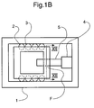
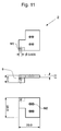
- Fig. 1A shows schematically a positioner comprising a base element 1 which is to be fixed, for example to an optical table, instrument housing etc., and a carriage element 2 on which an object to be moved can be mounted or against which a load to be acted upon can be applied.
- Carriage element 2 is slidably mounted in base element 1 via bearings 3 which provide tracking in the direction of movement (left-to-right or right-to-left in Fig. 1A).
- Carriage 2 is fixed to one end face of a piezoelectric element 4 which is extensible in the direction of movement.
- the other side of the piezoelectric element 4 is fixed to one end face of a rod 5 which extends through an aperture in the base element 1, the aperture and rod 5 experiencing a relative frictional force of magnitude F in the direction of movement.
- a sawtooth voltage signal having a slow rising edge and a rapidly decaying falling edge is applied to the piezoelectric element 4.
- the rod 5 remains stuck to the aperture of the base element 1 while the length of the piezoelectric element 4 slowly increases, thus pushing the carriage to the left in Fig. 1A.
- the length of the piezoelectric element 4 rapidly decreases and, due to the inertia of the carriage (including any external load thereon), causes the rod 5 to slip in the aperture while the carriage 2 remains static.
- an inverted sawtooth voltage signal is applied to the piezoelectric element 4.
- the rod 5 remains stuck to the aperture of the base element 1 while the piezoelectric element 4 slowly contracts, thus pulling the carriage 2 to the right in Fig. 1A.
- the piezoelectric element 4 rapidly expands and, due to the inertia of the carriage (including any external load thereon), causes the rod 5 to slip in the aperture while the carriage 2 remains static.
- the sawtooth drive signal is thus subdivided into two phases, one which is intended to produce slippage between rod and base element whilst the carriage remains still (slip phase) and one which is intended to move the carriage whilst the rod and base element remain stuck together (stick phase).
- Fig. 1B shows an equivalent arrangement to that of Fig. 1A, but with the piezoelectric element 4 secured to the base element 1 and the rod 5 extending through an aperture in the carriage 2 so that the frictional engagement F is between rod and carriage, rather than rod and base element as in Fig. 1A.
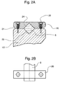
- Fig. 2A shows schematically a section through the plane XII of Fig. 1A or Fig. 1B according to one design of the region of frictional engagement and Fig. 2B shows the arrangement of Fig. 2A in plan view.
- Rod 5 is of square section and is slidably seated in a V-groove 23 machined in the base element (Fig. 1A) or carriage element (Fig. 1B) and a further V-groove 24, which faces the first-mentioned V-groove, machined in a collar 20.
- Collar 20 biases rod 5 in the V-groove 24 in the base/carriage element by means of a pair of screws 22 each biased by a respective spring 21 arranged in extension coaxially and concentrically around the screw concerned.
- the biasing force applied, and thus the magnitude of the frictional force F can be ajusted via adjustment of the screws 22.
- Typical frictional forces F vary between 1/2 to 10 Newtons, although values outside this range could also be set if desired. Generally a higher frictional force value F will provide a greater load capapability of the positioner but increase the tendecy to wear.
- a calibrated force guage can be used to measure the force required to make rod 5 slide, i.e.
- the rod could for example seat in a slot in the base/carriage element, with the flat base of the slot being in contact with a corresponding flat surface of a rod of square, rectangular, triangular or hemispherical cross-section.
- Fig. 3 shows schematically a section through the plane XII of Fig. 1A or Fig. 1B according to an alternative design of the region of frictional engagement.
- Rod 5 is of circular section and is slidably arranged in a precision machined bore in the base element (Fig. 1A) or carriage element (Fig. 1B), thus forming an arrangement in the manner of a piston and sleeve.
- Figs. 4A to 4C show details of a first exemplary drive signal, the effect of which on the positioner is explained with reference to Fig. 1A.
- Fig. 4A shows motion of the carriage 2 from left to right in Fig. 1A
- the inverted waveform shown in Fig. 4C will generate motion from right to left in Fig. 1A
- Fig. 4B shows a TTL signal which can be input into the drive circuit shown in Fig. 5 for generating the waveforms according to either Fig. 4A or 4C.
- a drive signal according to Fig. 4A or 4C is of especial practical interest since it can be generated by a simple circuit, for example that of Fig. 5, by periodically charging one capacitor and discharging another in an RC network.
- Fig. 5 is described in more detail further below.
- the drive signal shown in Figs. 4A or 4C is a voltage signal and has a generally sawtooth form.
- Each sawtooth has an exponentially rising portion, rising over a time T 1 from zero voltage to a peak value V max with a rise rate characterised by a value ⁇ 1 and a decaying portion falling exponentially from the above-mentioned peak voltage value to zero over a time T 2 at a decay rate characterised by a value ⁇ 2 .
- the relative values of F and F M can be visualised with reference to Fig. 1A or Fig. 1B as representing the competition between, on the one hand, the piezoelectric element 4 pushing or pulling the carriage 2 against the carriage's own inertia and, on the other hand, pushing or pulling the rod 5 overcoming the frictional force F as the piezoelectric element 4 expands or contracts respectively.
- a positioner which is to be operated with a negative exponential portion of this kind to produce the slip part of the slip-stick cycle thus needs to be designed such that the unwanted recoil portion of the cycle which occurs at F>F M is as small as possible. This is ensured by designing the positioner such that ⁇ 2 ⁇ ⁇ (Mx max /F o ) .
- the recoil motion described above is generally undesirable. It reduces energy efficiency and net positioning speed by reducing the net step size to x max -x recoil .
- the greater the recoil motion the greater the amount of energy expended to produce a given displacement. This may be an important consideration in cryogenic applications.
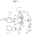
- Fig. 5 shows a drive circuit for generating a drive signal according to Fig. 4A or 4C.
- a TTL signal according to Fig. 4B is applied as an input to a control circuit 10 which delivers two identical outputs via respective single-ended amplifiers 14 and 14' to the gates of respective enhancement-mode field effect transistors 15 and 15' configured with substrate tied to source.
- the source of FET 15' is connected to a DC voltage source, for example a zero to fifty volt source. The specification of the voltage source will depend on the desired peak signal voltage V max .
- the drain of FET 15' is connected to one of a bank of resistors via a multipole switch 17', the other side of which resistors are connected together and lead to one terminal of a piezoelectric crystal oscillator 16.
- the drain of FET 15 is earthed.
- the source of FET 15 is connected to a further bank of resistors via a further multipole switch 17, the other side of which resistors are connected together and to those of the first mentioned bank of resistors and thus lead to the same terminal of the piezoelectric crystal oscillator 16.
- the other terminal of the piezoelectric crystal oscillator 16 is supplied either directly to the output of the circuit or to the output via an invertor 13, the supply route being determined by the position of a twin pole switch 12.
- the speed of motion is determined by the frequency of the input square wave pulse train.
- Single asynchrous steps can also be produced by inputting individual pulses.
- One each of switches 17 and 17' are selected to define the rise and fall times ⁇ 1 and ⁇ 2 as shown in Figs. 4A and 4C.
- the direction of motion is reversed by flipping switch 12.
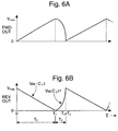
- Figs. 6A and 6B shows a second exemplary drive signal.
- the waveform shown in Fig. 6A will generate motion of the carriage 2 from left to right in Fig. 1A, whereas the inverted waveform shown in Fig. 6B will generate motion from right to left in Fig. 1A.
- These drive signals can for example be generated by a programmable function generator.
- the drive signal shown in Fig. 6A is a voltage signal and has a generally sawtooth form.
- Each sawtooth has a linearly rising portion, rising over a time T 1 from zero voltage to a peak value V max with a rise rate characterised by a value c 1 , and a decaying portion falling in an inverse parabola from the above-mentioned peak voltage value to zero over a time T 2 at a decay rate characterised by a value c 2 .
- the drive signal according to Figs. 6A and 6B has in principle several advantages over that of Figs. 4A and 4C.
- the slip phase does not give rise to a recoil effect since F M is time invariant and selected such that F M >F throughout.
- the stick phase does not limit the maximum drive frequency in the same way as for the signal of Figs. 4A and 4C since the constraints imposed by the exponential time constant ⁇ 1 are not present.
- a function generator may have to be used to generate the signal of Figs. 6A and 6C, whereas the relatively simple circuit of Fig. 5 can be used to generate the signal of Figs. 4A and 4C.
- the most appropriate choice of drive signal will depend on the requirements of each individual application.
- a real drive signal cannot reproduce discontinuities, such as at peak voltage in Fig. 6B, the voltage profile being rounded off in a real system.
- a third examplary drive signal (not shown) is a variation of that shown in Figs. 4A and 4C, in which the positive exponential component of Figs. 4A and 4C is substituted with a linear component.
- a commercial wave generator was used to generate a signal of the third exemplary kind having a linear portion with a rise/fall time adjustable between one second and one tenth of a millisecond, a negative exponential portion with a fixed decay constant of three microseconds and a peak voltage adjustable between zero and 100 volts.
- the piezoelectric element 4 and rod 5 are however of non-zero compliance and the consequences of this are now considered.
- the piezoelectric element 4 and rod 5 are treated as one-dimensional springs of spring constant k p and k s respectively.
- a spring constant sometimes referred to as an elastic stiffness constant, is a measure of linear stiffness of a body and is inversely proportional to compliance.
- V min can be approximated by equating the extension ⁇ l e of the compliant piezoelectric element which is needed to generate a force of F with the deformation ⁇ l p of the piezoelectric element as a function of applied voltage.
- the effect of the non-infinite stiffness of the piezoelectric element is to reduce step size by a factor of (V max -V min )/V min compared to what it would be if the piezoelectric element 4 and rod 5 were infinitely stiff.
- the effect is illustrated schematically in Fig. 7 which is a graph of step size x against applied peak voltage V max . If V max ⁇ V min then no motion is produced. If V max > V min then motion is produced but the step size is smaller than would be expected if zero compliance were assumed, in which latter case the curve shown would be a straight line intersecting the V max axis at the origin rather than at V min . The curve is approximately linear above threshold. Ideally a positioner should be designed such that V min ⁇ V max .
- the threshold voltage V min is of importance as its value defines a minimum for the peak voltage V max . If for example V min is around 80 Volts as for example in Anders et al (see Fig. 4 thereof) then drive voltages peaking at several hundred volts need to be used, in which case the drive circuitry becomes relatively high voltage circuitry (>100 volts) with the ensuant cost, size and safety drawbacks. High voltage systems are also generally undesirable when the positioner is to be operated in a vacuum chamber or in a cryostat, in which latter case energy consumption considerations are also important, this being a further drawback of high voltage drive signals.
- the drive circuitry is preferably of low voltage construction and the voltages in the drive signal also of as low voltage as possible.
- Fig. 8 shows a piezoelectric tube of hollow cylindrical structure for use as the piezoelectric element.
- the tube has an outside diameter ⁇ , wall thickness W, length l and end-face area A, this being equal to the wall thickness W multiplied by the circumference ⁇ of the tube.
- An electrode layer extends around the outside surface of the cylinder and a further electrode layer extends around the inside surface of the cylinder, across which electrodes a voltage is applied in order to expand the tube lengthways along its principal axis.
- the threshold voltage V min which should ideally be zero, does not depend on either the length of the tube l or its wall thickness W so that, perhaps contrary to intuition, providing a piezoelectric tube with thicker walls or with a greater length will not serve to reduce the threshold voltage.
- what will serve to reduce the threshold voltage is to make the piezoelectric tube from a material with a large Young's modulus E and a large piezoelectric tensor coefficient d 31 and to choose a tube with a large diameter ⁇ .
- Fig. 9 shows a piezoelectric stack of cylindrical structure for use as the piezoelectric element.
- the stack has a circular crosssection and is built up of n platelets of piezoelectric material each of thickness d and diameter ⁇ yielding a stack of height l.
- Each platelet is separated by an electrode layer, the thickness of which is assumed to be negligible, via which voltage is applied to distort the stack lengthways along its principal axis.
- ⁇ l p d 33 nV where d 33 is the appropriate piezoelectric tensor component.
- piezoelectric stacks of circular cross-section was considered in the above analysis to allow a direct comparison with piezoelectric tubes, which are circular in cross-section. Piezoelectric stacks of other cross-sectional shapes, such as square, are also suitable.
- the design of the rod 5 is now considered.
- the rod 5 should be stiffer than the piezoelectric element 4 so as to avoid rod distortion during operation, which for example may result in wide step-to-step fluctuations in F or even jamming.
- the equations and numerical examples are for a rod of circular cross-section, as illustrated in Fig. 3.
- the rod may however be for example of square-section, as illustrated in Fig. 2, or of rectangular cross-section or of semicircular or triangular cross-section.
- the rod should have, and thus be made of a material having a large Young's modulus. Consequently, materials with a relatively low Young's modulus such as quartz (5.44 x 10 10 N/m 2 ), brass (also 5.4) and aluminium (7.6) are not generally preferred as rod material, although working devices could be made using such material.
- Phosphor bronze (12) has a larger value than for example the ceramic piezoelectric materials PI141 (7.9) or EBL4 (9.2) ceramic, i.e. a suitable material for the piezoelectric element, and could perhaps be used.
- the preferred materials are stainless steel (20) and tungsten (39). Stainless steel is less costly than tungsten and more readily machined and is thus an attractive alternative to tungsten despite the fact that its Young's modulus is only roughly one half of that of tungsten.
- equation (6) can still be utilised as a design equation in respect of the rod dimensions.
- the positioner of the second embodiment comprises four main components: a lower plate 1 (Fig. 10) serving as the base element, an upper plate 2 (Fig. 11) serving as the carriage element, an elongate actuator assembly 4/5/6 (Figs. 12A and 12B) and a bearing assembly 3 (Figs. 13A and 13B), the assembled positioner being shown schematically in perspective view in Fig. 14.
- the external dimensions of the positioner of the second embodiment are 28 x 28 x 10 millimetres.
- the positioner of the second embodiment is designed to operate with a 100 nanometre step size and a total travel of approximately 1 centimetre.
- Fig. 10 is a technical drawing to scale in first angle projection of the lower plate 1.
- Lower plate 1 has precision machined therein a through hole 7 of diameter 3.000mm, hole 7 being for receiving rod 5 of the actuator assembly to form a barrel and piston arrangement having a relative frictional engagement characterised by a force F.
- the diameters of rod 5 and/or hole 7 are adjusted by polishing or other standard methods to produce a push fit of the required frictional force value F.
- the magnitude of the force F can be measured as polishing or the like procedes using a calibrated force guage.
- the U-shaped cross-section of the plate in which the bearing assembly 3 is received can be seen.
- Fig. 11 is a technical drawing to scale in first angle projection of the upper plate 2.
- the through hole 8 in the upper plate is for receiving a location stub 6 of the actuator assembly.
- an M2 thread is provided for receiving a grub screw for securing the location stub 6, and thus one end of the actuator assembly, to the upper plate 2.
- Stub 6 has no key functional role and can be dispensed with in variations on the design.
- the piezoelectic stack could be glued with epoxy resin directly onto a face of the upper plate. Location of the piezoelectic stack could then be provided by machining a small recess at the desired area.
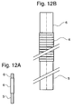
- Figs. 12A and 12B show the actuator assembly which is elongate and comprises rod 5, piezoelectric element 4 and a further rod 6.
- Fig. 12A is drawn to the same scale as Figs. 10 and 11 for ease of comparison, whereas Fig. 12B is an enlarged schematic representation.
- Further rod 6 serves as a locating stub and is referred to as a stub to differentiate it from rod 5.
- Rod 5, piezoelectric stack element 4 and stub 6 are glued together at their abutting end surfaces with epoxy resin.
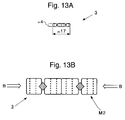
- Figs. 13A and 13B show the bearing assembly 3.
- Fig. 13A is drawn to the same scale as Figs. 10 and 11 for ease of comparison, whereas Fig. 13B is an enlarged schematic representation.
- the bearing assembly 3 comprises two pairs of crossed roller bearings, each of the four cages having two threaded bores running therethrough.
- the two pairs of bearings are received between the upper and lower plates 2 and 1 and located by means of screws passing through the respective sets of four M2 counterbore through holes in the upper and lower plates into the threads in the roller cages.
- the outer ones of each pair of roller bearing cages are each secured by two screws to the lower plate (Fig. 10) and the inner ones each by two screws to the upper plate (Fig. 11).
- the bearing pairs are biased to their preload value by applying force laterally in the direction shown by the arrows B in Fig. 13B.
- the biasing force which is adjusted at the end of assembly, is applied by means of three M2 grub screws fitted to the threads in the lower plate, which threads are evident in the two elevations on the left hand side of Fig. 10.
- Other types of bearing for example linear ball bearings, could also be used.
- the positioner In operation, the positioner according to the second embodiment moves a mass of 100 grammes attached to the upper plate in any direction including vertical at speeds of one millimetre per second. A mass of half a kilogramme is moved when the positioner is mounted horizontally.
- the positioner When the positioner is mounted horizontally, the load resulting from an object mounted on the upper surface of the upper plate 2 produces forces acting perpendicular to the direction of movement so that the step size will be independent of the mass of the object to be moved regardless of the functional form of the drive signal, e.g. even for the drive signal illustrated in Fig. 4. Moreover, the value of the frictional force F is independent of the mass of the object for any mounting orientation, since, due to the design, the object to be moved, or any other type of load, does not press on rod 5, the force being received by bearing assembly 3. This is a major advantage since the positioner will operate substantially the same for a wide range of object masses, or other vertically applied loads, when the positioner is mounted horizontally. The positioner can thus be supplied with a general specification for horizontally mounted operation in which step size as a function of peak drive voltage is independent of object mass over a wide range of object masses.
- Rod 5 is a square-section rod, as shown in Fig. 2, rather than a circular-section rod.
- the square section rod 5 is held substantially as shown in Figs. 2A and 2B in the lower plate 1 in the same position as the rod of the second embodiment.
- a calibrated force guage was used in the manner described further above to set the frictional force F, in each case to a value greater than one Newton.
- Rod 5 has a length of 12mm and a square cross-section of dimensions 5mm by 5mm.
- Piezoelectric element is cylindrical, being 7mm long and 5mm in diameter and extends along its principal axis by four nanometres per 0.150 volts applied.
- Stub 6 is dispensed with, piezoelectric stack being glued directly to the upper plate as mentioned above in connection with the second embodiment.
- the upper plate (carriage) has a mass of thirty grammes.
- a drive signal according to the above-described concrete example of the third exemplary kind was used.
- V min was approximately 8 volts, no motion resulting if V max ⁇ 8V.
- V max set at 8 volts and a drive frequency of 10 kHz a speed of approximately 0.5mm/sec was observed, from which a step size of 50 nanometres can be deduced.
- General operation was performed with V max set at 20 volts. At this peak voltage and with a drive frequency of 10 kHz a speed of approximately 3mm/sec was observed, from which a step size of 300 nanometres can be deduced.
- Speeds as low as 5mm per day were produced.
- Fig. 14 shows the positioner of the second embodiment in perspective view with the lower plate 1 of Fig. 10, the upper plate 2 of Fig. 11, the elongate actuator assembly 4/5/6 of Figs. 12A and 12B and the bearing assembly 3 of Figs. 13A and 13B visible.
- the positioner of the second embodiment has a total mass of 35 grammes of which the carriage has a mass of 11 grammes and the rod a mass of 1.1 grammes.
- Typical values selected for the frictional force F in the second and third embodiments are 0.5 to 1.5N. In the positioners in which resilient biasing means for the rod is provided, for example with a compression spring or leaf spring, this value can be adjusted when desired to the value required.
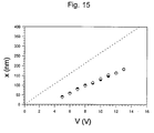
- Fig. 15 is a graph of test results taken during room temperature operation of the positioner of the second embodiment arranged such that movement is in the horizontal plane (xy-positioner).
- the graph shows the variation in step size x as a function of the peak voltage of a saw-tooth wave form applied as the drive signal. (A saw-tooth wave form is also used in the subsequent test curves of Figs. 16, 19, 20 and 21).
- the step sizes shown are average step size values taken over a path of several millimetres. At each peak voltage the positioner was traversed in one direction to provide a first data point, these data points being represented by hollow diamonds in Fig. 15, and then traversed in the return direction with the inverse wave form of the same modulus peak voltage and with the same total number of pulses to provide a second data point, these data points being represented by solid circles in Fig. 15. The dashed line passing through the origin is the ideal response for an infinitely stiff drive train. (A similar procedure was followed when measuring the subsequent test curves of Figs. 16, 19, 20 and 21).
- the threshold voltage Vmin discussed further above with reference to Fig. 7, was observed to be approximately 4 volts.
- step size can be varied as desired in a reproducible manner by varying the peak voltage of the drive signal, so that a high degree of flexibility of operation can be achieved with the same positioner simply by changing the magnitude of the drive signal.
- step sizes of 50 nanometre or above can be selected.
- drive frequencies of 1 kilohertz are typically used for 'rapid' movement which, with reference to Fig. 15, corresponds at room temperature to a speed of travel of approximately 50 ⁇ m/s to 200 ⁇ m/s for drive signals having peak voltages of 5 to 15 V respectively.
- Lower frequencies or single pulses can be used as desired by the application concerned.
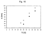
- Fig. 16 is a graph showing the results of a test similar to that described with reference to Fig. 15, but taken at a temperature of 4.2 Kelvin.
- the step size is observed to be considerably smaller than at room temperature and the threshold voltage of around 20 volts to be considerably higher. This is owing to the reduction in the magnitude of the piezoelectric coefficients as temperature decreases. Step sizes of 15 nanometres or above can be selected.
- a relatively small, but systematic discrepancy in step size between forwards movement (solid circles) and backwards movement (hollow diamonds) is also observed, which was not the case for room temperature operation.
- the peak voltage of the drive signal was set to around 50 volts.
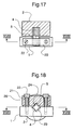
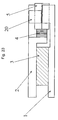
- Figs. 17 and 18 show a positioner according to a third embodiment of the invention respectively in side view and in plan view from underneath.
- the upper part of Fig. 17 is shown in section through the section XVII of Fig. 18 to reveal more clearly the piezoelement 4 and its arrangement relative to the carriage 2 and rod 5.
- the upper part of Fig. 18 is also shown in section, with the section being through the section XVIII of Fig. 17 and made to reveal more clearly the spring biasing arrangement of the rod 5 in its receiving aperture 23 and 24.
- the positioner of the third embodiment has no bearing assembly but uses the rod and rod receiving parts for guidance.
- the carriage 2 is cylindrical with an axially positioned hollow in one end face of the cylinder for receiving one end of the piezoelement 4, the other end of which is adhesively bonded to the square-section rod 5.
- the rod is biased with a pair of screws 22 and coil springs 21 mounted in a collar 20 in an arrangement similar to that described with reference to Fig. 2, the screws being received in threads in the base 1 to allow a desired biasing force F to be adjusted by adjustment of the screws 22 to vary the degree of compression in the springs 21.
- the positioner of the third embodiment has a total travel of approximately 4 millimetres and a total mass of 79 grammes of which the carriage has a mass of 45 grammes and the rod a mass of 1.8 grammes.
- the rod 5 is made of steel and has a square section of 5 by 5 millimetres.
- the base area defined by the base element 1 and collar 20 is approximately 20 by 27 millimetres.
- the height is approximately 28 millimetres.
- Fig. 19 is a graph of test results taken during room temperature operation of the positioner of the third embodiment arranged such that the movement is vertical (z-positioner).
- the graph shows the variation in step size x as a function of the peak voltage of a saw-tooth wave form applied as the drive signal.
- the test measurements were taken at a drive frequency of 500 hertz over a travel of 3.1 millimetres.
- Fig. 20 The sensitivity of the positioner of the third embodiment when arranged to provide vertical movement (z-positioner) to variations in load is shown in Fig. 20. Measurements were taken with loads of 12, 20 and 30 grammes placed on the carriage 2. The measurements were taken with a drive signal having a peak voltage of 40 volts. As can be seen from Fig. 20, no significant variation in step size x was observed at room temperature between upwards movement (squares) and downwards movement (triangles) as the load was varied from zero to a load of 30 grammes, although the difference in step size between upwards and downwards movement, already apparent from Fig. 19, is evident.
- Fig. 21 is a graph showing the results of a test similar to that described with reference to Fig. 19, but taken at a temperature of 4.2 Kelvin.
- the differences in comparison to room temperature operation are similar to the differences discussed with reference to Figs. 15 and 16 for the second embodiment.
- the difference in step size for upwards movement (squares) and downwards movement (triangles) is around 50 nanometres.
- the minimum step sizes that can be set are approximately 50 nanometres for upwards movement and 90 nanometres for downwards movement.
- the positioner of the third embodiment can be placed on the positioner of the second embodiment to provide an xyz-positioner, it being noted that the test results shown in Fig. 15 were taken with the positioner of the third embodiment, having a mass of 114 grammes, placed upon it.
- Figs. 22 and 23 show in plan and side view respectively a positioner according to a fourth embodiment of the invention.
- the positioner of the fourth embodiment comprises a base element in the form of a base plate 1 and a carriage in the form of a top plate 2 arranged on top of the base plate.
- the base and top plates 1 and 2 are generally square, having outer dimensions of 50 by 50 millimetres and 46 by 46 millimetres ("a") respectively and are made of aluminium.
- the aperture in the base plate 1 extends through a full arc to form a circular aperture, whereas the aperture in the top plate does not extends through a complete arc, but around approximately 330°, there being a cut away corner region of the top plate 2 formed by two terminal sides of the top plate which extend at right angles to each other from respective outer sides of the top plate to respective ends of the periphery of the arcuate aperture formed in the top plate.
- One of the terminal sides of the cut-away corner region extends downwards below the plane of the top plate 2 to form a flange having an abutment face for receiving one of the end faces of a piezoelectric element 4.
- the piezoelectric element is a piezoelectric stack of approximately 4 millimetres in length and extending lengthways by 4 micrometres per 150 volts of applied voltage at room temperature.
- top and base plates 1 and 2 are slidably connected to each other via respective halves of two bearing assemblies 3 in the form of ball slides which extend along an opposing pair of sides of the plates so as not to obscure the access hole and in a slightly staggered configuration.
- Each ball slide is a preassembled unit of dimensions 19.05 by 9.65 millimetres in the plane of the plates and 5.84 millimetres perpendicular to the plane of the plates, has a travel of 12.7 millimetres and a specified load bearing capacity of 680 grammes.
- the preassembled units have threaded bores via which their respective sliding halves are secured via screw fasteners to the base and top plates.
- the corner region of the base plate 1 lying below the cut-away corner region of the top plate 2, when considered in plan view (i.e. with reference to Fig. 22), has in the upper face thereof a V-groove for receiving two adjacent sides of a square section rod 5, one end face of which is bonded to the other of the end faces of the piezoelectric element 4 to form a drive train with the rod 5 and piezoelectric element 4 extending in series, as in the previous embodiments.
- the rod 5 has a cross-section of 5 by 5 millimetres and a length of 12 millimetres.
- a collar 20 has a V-groove for receiving the other two sides of the square section rod 5 and two counterbore holes 19, one on each side of the V-groove, for receiving a pair of screws (not shown) biased by respective compression springs (not shown) to define the magnitude of the frictional force F between the base and top plates 1 and 2 in the same way as the arrangement described with reference to Figs. 2A and 2B.
- the frictional force F is typically set, by adjusting the bias, to have a value of between 1 and 10 Newtons, although forces of greater than 10 Newtons can be set if desired.
- the thickness of the positioner of the fourth embodiment is approximately 15 millimetres, giving overall dimensions of 50 by 50 by 15 millimetres for a single axis positioner, or 50 by 50 by 30 millimetres for a twin axis positioner comprising two single axis positioners stacked on top of one another to provide mutually perpendicular axes of movement.
- the positioner of the fourth embodiment is suitable for use at room temperature as a positioner in a conventional microscope for positioning a microscope slide or the like under an objective lens. Two such positioners are stacked on top of one another to provide the desired xy-positioning capability.
- the large access hole can accomodate a microscope objective lens of 23 millimetres in diameter and still allow several millimetres of travel in the x and y directions.
- Such an xy-positioner may also be used in near-field optics as a so-called coarse positioner, or even as a combined coarse and fine positioner, fine positioning being achievable by ensuring that the double differential of the temporal evolution of the drive voltage applied to the piezoelectric element 4 is sufficiently small so as not to induce slippage between the rod 5 and the collar 20.
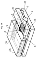
- Fig. 24 is a perspective view of a positioner according to a fifth embodiment of the invention.
- the positioner of the fifth embodiment comprises a base element in the form of a square base plate 1, on top of which are arranged a carriage in the form of a rectangular top plate 2 and a rectangular collar 20, the lengths of the respective major sides of the top plate 2 and collar 20 being approximately eqaul to the side length of the base plate 1.
- the base plate 1 has on its upper side a pair of V-grooves 25 extending parallel to each other along the full length of respective opposite sides of the base plate.
- the top plate 2 has on its lower side a corresponding pair of V-grooves 26 arranged to face the V-grooves 25 of the base plate 1 and extending along the full length of respective minor sides of the top plate 2, the minor side length of the top plate 2 being approximately two-thirds of the side length of the base plate 1.
- the top and base plates 1 and 2 are slidably engaged by two sets of ball bearings 3 seated in the V-grooves 25 and 26, the ball bearings 3 being caged in a sheet-like cage (not shown).
- the collar 20 has in its lower side a V-groove extending along its full minor side length parallel to the V-grooves 25 and 26 and arranged midway along the major side of the collar 20. There is a corresponding V-groove in the upper side of the base plate arranged to face the collar V-groove. A rod 5 of square section is seated in the collar V-groove and corresponding base plate V-groove to provide frictional engagement in the manner described further above in connection with the previous embodiments.
- the magnitude of the frictional force F between the collar 20 (and thus the base plate 1) and top plate 2 is set in the same way as in the arrangement described with reference to Figs.
- the base plate has dimensions 30 x 30 x 6 mm, the top plate 30 x 15 x 6 mm and the collar 30 x 10 x 6 mm.
- the ball bearings have a diameter of 3 millimetres.
- the rod is 4 x 4 mm in section and 15.5 mm in length.
- the piezoelectric element is 4 x 4 mm in section and 5 mm in length.
- the positioner of the fifth embodiment can be made to be operable at low temperatures (e.g. liquid Nitrogen or Helium temperatures) and in high magnetic fields (e.g. 1 to 10 Tesla).
- low temperatures e.g. liquid Nitrogen or Helium temperatures
- high magnetic fields e.g. 1 to 10 Tesla
- the base plate 1, top plate 2, collar 20, rod 5 and fasteners are made of titanium
- the ball bearings are made of ruby
- the cages are made of plastic.
- the ball bearings could alternatively be made of sapphire, glass or ceramic.
- the cages could alternatively be made of non-magnetic metal sheet.
- an alternative material to titanium is brass.
Abstract
Description
- Fig. 1A
- A schematic representation of a positioner according to a first embodiment of the invention;
- Fig. 1B
- A schematic representation of a positioner according to an equivalent to the first embodiment of the invention;
- Fig. 2A
- Cross-section through plane XII of Fig. 1A or 1B showing schematically an arrangement for providing frictional engagement between carriage and base by means of a rod of square-section seated in a pair of facing V-grooves;
- Fig. 2B
- Plan view of the arrangement of Fig. 2A;
- Fig. 3
- Cross-section through plane XII of Fig. 1A or 1B showing schematically an arrangement for providing frictional engagement between carriage and base by means of a rod of circular section;
- Fig. 4A
- Graph showing a first exemplary drive signal, having positive and negative exponential portions, suitable for driving a positioner according to embodiments of the invention,
- Fig. 4B
- Graph showing a TTL signal which can be used to generate a drive signals according to Fig. 4A;
- Fig. 4C
- Graph showing an inverted form of the first exemplary drive signal for driving a positioner in the opposite direction from the drive signal of Fig. 4A the inverted form also being generatable with the TTL signal of Fig. 4B;
- Fig. 5
- Drive circuit for converting the TTL signal shown in Fig. 4B selectively into either the drive signal shown in Fig. 4A or the inverted form of the drive signal shown in Fig. 4C;
- Fig. 6A
- Graph showing a second exemplary drive signal, having parabolical and linear portions, suitable for driving a positioner according to embodiments of the invention;
- Fig. 6B
- Graph showing an inverted form of the first exemplary drive signal for driving a positioner in the opposite direction from the drive signal of Fig. 6A;
- Fig. 7
- Graph showing step size x plotted against peak voltage Vmax of the drive signal for a piezoelectric element of non-zero compliance, i.e. finite stiffness;
- Fig. 8
- Piezoelectric tube for use as the piezoelectric element;
- Fig. 9
- Piezoelectric stack for use as the piezoelectric element;
- Fig. 10
- Technical drawing in first-angle projection of a lower plate (base element) of a positioner according to a second embodiment of the invention;
- Fig. 11
- Technical drawing in first-angle projection of an upper plate (carriage element) of a positioner according to the second embodiment of the invention;
- Fig. 12A
- Technical drawing of an actuator element comprising a piezoelectric stack and rods of a positioner (actuating element) according to the second embodiment of the invention;
- Fig. 12B
- An enlarged schematic representation of Fig. 12A;
- Fig. 13A
- Technical drawing of a bearing assembly comprising two sets of two crossed-roller bearings according to the second embodiment of the invention;
- Fig. 13B
- An enlarged schematic representation of Fig. 13A;
- Fig. 14
- Schematic perspective view of a positioner according to the second embodiment of the invention assembled from the components shown in Fig. 10 to 13;
- Fig. 15
- Graph showing test results of step size x plotted against peak voltage V of the drive signal for a positioner according to the second embodiment at room temperature;
- Fig. 16
- Graph showing test results for the same positioner as in Fig. 15, but at a temperature of 4.2 Kelvin;
- Fig. 17
- Side view of a positioner according to a third embodiment of the invention, with the upper parts shown in section taken through section XVII of Fig. 18;
- Fig. 18
- Plan view from underneath of the positioner of Fig. 17, with the upper parts shown in section taken through section XVIII of Fig. 17;
- Fig. 19
- Graph showing test results of step size x plotted against peak voltage V of the drive signal for a positioner according to the third embodiment at room temperature;
- Fig. 20
- Graph showing test results of step size at room temperature with different loads placed on the carriage;
- Fig. 21
- Graph showing test results for the same positioner as in Fig. 19, but at a temperature of 4.2 Kelvin;
- Fig. 22
- A schematic plan view of a positioner according to a fourth embodiment of the invention;
- Fig. 23
- A schematic side view of the positioner shown in Fig. 22; and
- Fig. 24
- A schematic perspective view of a positioner according to a fifth embodiment of the invention.
Claims (12)
- An inertial positioner comprising a base (1) and a carriage (2) connected to one another so as to allow inertial motion of the carriage (2) relative to the base (1) in a positioning direction, there being an actuator (4, 5) for impelling the carriage (2) in the positioning direction, characterised in that the actuator (4, 5) comprises an electrically extensible piezoelectric element (4) and a rod (5) connected in series therewith, the actuator (4, 5) extending between the carriage (2) and the base (1) with the piezoelectric element (4) secured to one of the carriage (2) and the base (1) and the rod (5) forming a frictional engagement with the other of the carriage (2) and base (1), such that extension of the piezoelectric element (4) either causes movement of the carriage (2) in the positioning direction, with the frictional engagement sticking, or slippage of the rod (5) in its frictional engagement, with the carriage (2) remaining still relative to the base (1).
- A positioner according to claim 1, wherein the frictional engagement between the rod (5) and said one of the carriage (2) and base (1) is formed by engagement over an area of contact between a surface portion of the rod (5) and a correspondingly shaped surface portion of the said one of the carriage (2) and base (1), slippage of the rod (5) being guided in a slippage direction defined by the surface portions.
- A positioner according to claim 2, wherein the rod (5) has a cross-section comprising at least one straight side, the area on the rod (5) surface defined by which forming at least part of said rod surface portion, the rod (5) preferably having a polygonal cross-section, the polygon further preferably being one of the group: square, rectangle and triangle.
- A positioner according to any one of claims 2 or 3, comprising means (20) for biasing the rod (5) against at least a part of said surface portion of the said one of the carriage (2) and base (1) with a force which has a major component in a direction perpendicular to the slippage direction.
- A positioner according to claim 4 and comprising means (21, 22) for adjusting the biasing force applied by the rod biasing means (20), so that different values of the frictional force (F) characteristic of the frictional engagement can be set.
- A positioner according to claim 5, wherein the biasing force adjustment means (21, 22) comprises spring means (21) and means (22) for adjusting the biasing force applied by the spring means (21).
- A positioner according to claim 4, 5 or 6, wherein the rod biasing means comprises a collar (20) arranged to press the rod (5) against said one of the carriage (2) and the base (1) to provide said frictional engagement.
- A positioner according to any one of claims 2 to 7, wherein said surface portion of the said one of the carriage (2) and base (1) comprises one of the group of a V-groove (23) and a slot (23).
- A positioner according to any one of the preceding claims, wherein the piezoelectric element (4) comprises either a piezoelectric stack, the stack having a cross-sectional area preferably of greater than at least one of the group: 10, 20, 30, 50 and 75 square millimetres, or a piezoelectric tube, the tube preferably having an outside diameter of greater than or equal to at least one of the group: 4, 6, 8 and 10 millimetres.
- A positioner according to any one of the preceding claims, wherein the rod (5) has a cross-sectional area of greater than at least one of the group: 3, 10, 20, 30, 50 and 75 square millimetres.
- A positioner according to any one of the preceding claims, wherein the base (1) and carriage (2) are slidably connected to one another via a bearing assembly (3).
- A positioner according to any one of the preceding claims, wherein the base (4) comprises a plate and the carriage (2) comprises a further plate, the two plates being slidably connected via the bearing assembly (3), respective sliding halves of which are secured to respective facing surfaces of the plates.
Applications Claiming Priority (4)
| Application Number | Priority Date | Filing Date | Title |
|---|---|---|---|
| GB9616456 | 1996-08-05 | ||
| GB9616456A GB2316221A (en) | 1996-08-05 | 1996-08-05 | Positioner using piezoelectric actuator |
| GBGB9705374.8A GB9705374D0 (en) | 1997-03-14 | 1997-03-14 | Positioner |
| GB9705374 | 1997-03-14 |
Publications (3)
| Publication Number | Publication Date |
|---|---|
| EP0823738A2 true EP0823738A2 (en) | 1998-02-11 |
| EP0823738A3 EP0823738A3 (en) | 1999-10-27 |
| EP0823738B1 EP0823738B1 (en) | 2005-09-07 |
Family
ID=26309820
Family Applications (1)
| Application Number | Title | Priority Date | Filing Date |
|---|---|---|---|
| EP97112450A Expired - Lifetime EP0823738B1 (en) | 1996-08-05 | 1997-07-21 | Inertial positioner |
Country Status (5)
| Country | Link |
|---|---|
| US (1) | US5912527A (en) |
| EP (1) | EP0823738B1 (en) |
| AT (1) | ATE304224T1 (en) |
| DE (1) | DE69734132T2 (en) |
| GB (1) | GB2316222B (en) |
Cited By (10)
| Publication number | Priority date | Publication date | Assignee | Title |
|---|---|---|---|---|
| WO1998019347A2 (en) * | 1996-10-26 | 1998-05-07 | Artur Zrenner | Piezoelectric or electrostrictive inertia drive for displacing or positioning in particular heavy objects |
| WO2000024065A1 (en) * | 1998-10-17 | 2000-04-27 | Carl Zeiss Jena Gmbh | Device for positioning an object |
| DE102005026708A1 (en) * | 2005-06-09 | 2006-12-21 | Attocube Systems Ag | Positioner with solid-body joint |
| EP1755176A3 (en) * | 2005-08-15 | 2007-10-31 | Fujinon Corporation | Actuator |
| US7301257B2 (en) * | 2005-10-14 | 2007-11-27 | Academia Sinica | Motion actuator |
| US7679848B2 (en) | 2005-08-12 | 2010-03-16 | Fujinon Corporation | Actuator and lens drive apparatus |
| EP1887639A3 (en) * | 2006-08-11 | 2011-12-28 | Konica Minolta Opto, Inc. | Driving device |
| WO2012123251A1 (en) | 2011-03-14 | 2012-09-20 | Smaract Gmbh | Method for controlling an inertial drive |
| US9692323B2 (en) | 2011-03-30 | 2017-06-27 | SmarAct Holding GmbH | Method for actuating a multi-actuator drive device |
| CN109756148A (en) * | 2019-03-20 | 2019-05-14 | 唐金岩 | The apparatus and method of active suppression parasitic motion principle piezoelectric actuator rollback movement |
Families Citing this family (24)
| Publication number | Priority date | Publication date | Assignee | Title |
|---|---|---|---|---|
| JPH10337057A (en) * | 1997-06-02 | 1998-12-18 | Minolta Co Ltd | Driver |
| US6894704B1 (en) * | 1999-11-22 | 2005-05-17 | Adobe Systems Incorporated | Processing complex regions of illustration artwork |
| GB2369489B (en) | 2000-11-23 | 2004-03-10 | Khaled Karrai | Inertial rotation device |
| US6736361B2 (en) * | 2001-09-04 | 2004-05-18 | Nline Corporation | Semiconductor wafer positioning system and method |
| US7486382B2 (en) | 2001-12-19 | 2009-02-03 | Carl Zeiss Smt Ag | Imaging device in a projection exposure machine |
| DE10225266A1 (en) | 2001-12-19 | 2003-07-03 | Zeiss Carl Smt Ag | Imaging device in a projection exposure system |
| JP2005287167A (en) * | 2004-03-29 | 2005-10-13 | Konica Minolta Opto Inc | Drive unit |
| WO2007022764A1 (en) | 2005-08-24 | 2007-03-01 | Smaract Gmbh | Rotatory bearing drive device |
| DE102006052175B4 (en) | 2006-11-02 | 2013-03-07 | SmarAct Holding GmbH | Inertial mover |
| US8059346B2 (en) | 2007-03-19 | 2011-11-15 | New Scale Technologies | Linear drive systems and methods thereof |
| DE102007053475B4 (en) | 2007-11-09 | 2016-09-01 | Karlsruher Institut für Technologie | positioning |
| TWI472471B (en) | 2011-06-03 | 2015-02-11 | Academia Sinica | Multi-axes actuating apparatus |
| WO2013038415A1 (en) * | 2011-09-13 | 2013-03-21 | Innowattech Ltd. | Modular piezoelectric generators with a mechanical force multiplier |
| JP6406593B2 (en) | 2013-12-28 | 2018-10-17 | 株式会社ミクロブ | Drive mechanism |
| DE102014014997B4 (en) | 2014-10-09 | 2018-05-17 | Attocube Systems Ag | Stick-slip drive, in particular piezo-actuated inertial drive |
| CN104467526B (en) * | 2014-12-01 | 2017-02-01 | 苏州大学 | Inertia stick-slip cross-scale motion platform capable of achieving unidirectional movement |
| US9791674B1 (en) | 2015-02-06 | 2017-10-17 | Apple Inc. | Miniature camera zoom actuator with magnet-induced friction |
| JP6451657B2 (en) * | 2016-01-29 | 2019-01-16 | Tdk株式会社 | Piezoelectric actuator |
| KR20180113197A (en) | 2016-02-11 | 2018-10-15 | 피직 인스트루멘테 (페이) 게엠베하 운트 코. 카게 | Method and apparatus for actuating electromechanical elements |
| CN106911264B (en) * | 2017-04-01 | 2019-04-09 | 西安交通大学 | Small-sized list piezoelectric stack drive-type bidirectional rotation inertia actuator and actuation method |
| CN110474562B (en) * | 2019-09-06 | 2024-03-12 | 仪晟科学仪器(嘉兴)有限公司 | Precise piezoelectric ceramic swinging table for ultrahigh vacuum |
| JP2020054228A (en) * | 2019-12-11 | 2020-04-02 | 株式会社ミクロブ | Drive mechanism |
| DE102020118300A1 (en) | 2020-07-10 | 2022-01-13 | SmarAct Holding GmbH | Inertial drive and related procedure |
| KR102481180B1 (en) | 2020-09-21 | 2022-12-23 | 포항공과대학교 산학협력단 | Piezoelectric motor with nanometer resolution |
Citations (2)
| Publication number | Priority date | Publication date | Assignee | Title |
|---|---|---|---|---|
| EP0675589A1 (en) * | 1994-03-29 | 1995-10-04 | Minolta Co., Ltd. | Driving apparatus using transducer |
| EP0747977A1 (en) * | 1995-06-08 | 1996-12-11 | Minolta Co., Ltd. | Movable stage utilizing electromechanical transducer |
Family Cites Families (13)
| Publication number | Priority date | Publication date | Assignee | Title |
|---|---|---|---|---|
| US3902084A (en) * | 1974-05-30 | 1975-08-26 | Burleigh Instr | Piezoelectric electromechanical translation apparatus |
| JPS5315060A (en) * | 1976-07-28 | 1978-02-10 | Hitachi Ltd | Inching device |
| US4219755A (en) * | 1977-03-18 | 1980-08-26 | Physics International Company | Electromotive actuator |
| US4195243A (en) * | 1978-11-06 | 1980-03-25 | Sperry Corporation | Piezoelectric wafer mover |
| JPS63262065A (en) * | 1987-04-16 | 1988-10-28 | Nippon Denso Co Ltd | Displacement enlarging device for piezoelectric actuator |
| JPS63299785A (en) * | 1987-05-29 | 1988-12-07 | Res Dev Corp Of Japan | Micro-movement device employing impact force of piezo-electric and electrostrictive element |
| US4874979A (en) * | 1988-10-03 | 1989-10-17 | Burleigh Instruments, Inc. | Electromechanical translation apparatus |
| US4890027A (en) * | 1988-11-21 | 1989-12-26 | Hughes Aircraft Company | Dynamic motor controller |
| US4968914A (en) * | 1989-03-24 | 1990-11-06 | Quanscan, Inc. | High resolution electromechanical translation device |
| US5260622A (en) * | 1989-03-24 | 1993-11-09 | Topometrix Corporation | High resolution electromechanical translation device |
| DE4015196C2 (en) * | 1989-05-12 | 1995-02-23 | Fuji Electric Co Ltd | Press with piezoelectric actuators and control thereof |
| US5205147A (en) * | 1989-05-12 | 1993-04-27 | Fuji Electric Co., Ltd. | Pre-loaded actuator using piezoelectric element |
| US5225941A (en) * | 1990-07-03 | 1993-07-06 | Canon Kabushiki Kaisha | Driving device |
-
1997
- 1997-07-16 GB GB9714909A patent/GB2316222B/en not_active Expired - Lifetime
- 1997-07-21 AT AT97112450T patent/ATE304224T1/en not_active IP Right Cessation
- 1997-07-21 DE DE69734132T patent/DE69734132T2/en not_active Expired - Lifetime
- 1997-07-21 EP EP97112450A patent/EP0823738B1/en not_active Expired - Lifetime
- 1997-07-28 US US08/901,848 patent/US5912527A/en not_active Expired - Lifetime
Patent Citations (2)
| Publication number | Priority date | Publication date | Assignee | Title |
|---|---|---|---|---|
| EP0675589A1 (en) * | 1994-03-29 | 1995-10-04 | Minolta Co., Ltd. | Driving apparatus using transducer |
| EP0747977A1 (en) * | 1995-06-08 | 1996-12-11 | Minolta Co., Ltd. | Movable stage utilizing electromechanical transducer |
Non-Patent Citations (2)
| Title |
|---|
| POHL D W: "Dynamic piezoelectric translation devices" REVIEW OF SCIENTIFIC INSTRUMENTS, JAN. 1987, USA, vol. 58, no. 1, pages 54-57, XP002113874 ISSN: 0034-6748 * |
| RENNER C ET AL: "A vertical piezoelectric inertial slider" REVIEW OF SCIENTIFIC INSTRUMENTS, MARCH 1990, USA, vol. 61, no. 3, pages 965-967, XP002113873 ISSN: 0034-6748 * |
Cited By (16)
| Publication number | Priority date | Publication date | Assignee | Title |
|---|---|---|---|---|
| WO1998019347A2 (en) * | 1996-10-26 | 1998-05-07 | Artur Zrenner | Piezoelectric or electrostrictive inertia drive for displacing or positioning in particular heavy objects |
| WO1998019347A3 (en) * | 1996-10-26 | 1998-06-25 | Artur Zrenner | Piezoelectric or electrostrictive inertia drive for displacing or positioning in particular heavy objects |
| WO2000024065A1 (en) * | 1998-10-17 | 2000-04-27 | Carl Zeiss Jena Gmbh | Device for positioning an object |
| US7579752B2 (en) | 2005-06-09 | 2009-08-25 | Attocube Systems Ag | Positioning device with a solid-body joint |
| DE102005026708B4 (en) * | 2005-06-09 | 2007-05-03 | Attocube Systems Ag | Positioner with solid-body joint |
| DE102005026708A1 (en) * | 2005-06-09 | 2006-12-21 | Attocube Systems Ag | Positioner with solid-body joint |
| US7679848B2 (en) | 2005-08-12 | 2010-03-16 | Fujinon Corporation | Actuator and lens drive apparatus |
| EP1755176A3 (en) * | 2005-08-15 | 2007-10-31 | Fujinon Corporation | Actuator |
| US7449815B2 (en) | 2005-08-15 | 2008-11-11 | Fujinon Corporation | Actuator |
| US7301257B2 (en) * | 2005-10-14 | 2007-11-27 | Academia Sinica | Motion actuator |
| EP1887639A3 (en) * | 2006-08-11 | 2011-12-28 | Konica Minolta Opto, Inc. | Driving device |
| WO2012123251A1 (en) | 2011-03-14 | 2012-09-20 | Smaract Gmbh | Method for controlling an inertial drive |
| DE102012202945A1 (en) | 2011-03-14 | 2012-12-13 | Smaract Gmbh | Method for controlling an inertial drive |
| US9722512B2 (en) | 2011-03-14 | 2017-08-01 | SmarAct Holding GmbH | Method for controlling an inertial drive |
| US9692323B2 (en) | 2011-03-30 | 2017-06-27 | SmarAct Holding GmbH | Method for actuating a multi-actuator drive device |
| CN109756148A (en) * | 2019-03-20 | 2019-05-14 | 唐金岩 | The apparatus and method of active suppression parasitic motion principle piezoelectric actuator rollback movement |
Also Published As
| Publication number | Publication date |
|---|---|
| GB2316222B (en) | 1998-07-01 |
| EP0823738B1 (en) | 2005-09-07 |
| DE69734132T2 (en) | 2006-07-13 |
| EP0823738A3 (en) | 1999-10-27 |
| ATE304224T1 (en) | 2005-09-15 |
| GB2316222A (en) | 1998-02-18 |
| DE69734132D1 (en) | 2005-10-13 |
| GB9714909D0 (en) | 1997-09-17 |
| US5912527A (en) | 1999-06-15 |
Similar Documents
| Publication | Publication Date | Title |
|---|---|---|
| EP0823738B1 (en) | Inertial positioner | |
| US7301257B2 (en) | Motion actuator | |
| Judy et al. | A linear piezoelectric stepper motor with submicrometer step size and centimeter travel range | |
| US5237238A (en) | Adjusting device for microscopic movements | |
| US4894579A (en) | Apparatus for effecting fine movement by impact force produced by piezoelectric or electrostrictive element | |
| EP0763881B1 (en) | Magnetic micro-mover | |
| US7877893B2 (en) | Measurement of micromovements | |
| Chang et al. | A high resolution long travel friction-drive micropositioner with programmable step size | |
| Hii et al. | Design, operation, and motion characteristics of a precise piezoelectric linear motor | |
| Baginsky et al. | High-energy capacitance electrostatic micromotors | |
| Jaecklin et al. | Comb actuators for xy-microstages | |
| US20040084996A1 (en) | Translation and rotation positioning motor | |
| Kleindiek et al. | Miniature three‐axis micropositioner for scanning proximal probe and other applications | |
| Kang et al. | Development of compact high precision linear piezoelectric stepping positioner with nanometer accuracy and large travel range | |
| Xu et al. | Microelectromechanical scanning tunneling microscope | |
| US6919666B2 (en) | Adjusting device for displacing individual elements of optical systems or of measuring systems | |
| GB2316221A (en) | Positioner using piezoelectric actuator | |
| Altfeder et al. | Low‐temperature scanning tunneling microscope with a reliable piezoelectrical coarse approach mechanism | |
| Kwon et al. | The design and characterization of a piezo-driven inchworm linear motor with a reduction-lever mechanism | |
| KR100439908B1 (en) | Electrostatic micro actuator | |
| JP4095913B2 (en) | High precision micro movement device | |
| Silveira et al. | A vertical inertial coarse approach for variable temperature scanned probe microscopy | |
| JP4073512B2 (en) | Drive device | |
| Anderson | A six-degree of freedom flexural positioning stage | |
| JPH0434226A (en) | Minute displacement device |
Legal Events
| Date | Code | Title | Description |
|---|---|---|---|
| PUAI | Public reference made under article 153(3) epc to a published international application that has entered the european phase |
Free format text: ORIGINAL CODE: 0009012 |
|
| AK | Designated contracting states |
Kind code of ref document: A2 Designated state(s): AT BE CH DE ES FR GB IE IT LI NL |
|
| AX | Request for extension of the european patent |
Free format text: AL;LT;LV;RO;SI |
|
| PUAL | Search report despatched |
Free format text: ORIGINAL CODE: 0009013 |
|
| AK | Designated contracting states |
Kind code of ref document: A3 Designated state(s): AT BE CH DE DK ES FI FR GB GR IE IT LI LU MC NL PT SE |
|
| AX | Request for extension of the european patent |
Free format text: AL;LT;LV;RO;SI |
|
| RIN1 | Information on inventor provided before grant (corrected) |
Inventor name: KARRAI, KHALED, PROF. DR. |
|
| RAP1 | Party data changed (applicant data changed or rights of an application transferred) |
Owner name: KARRAI, KHALED, DR. Owner name: HAINES, MILES, DR. |
|
| 17P | Request for examination filed |
Effective date: 20000407 |
|
| AKX | Designation fees paid |
Free format text: AT BE CH DE ES FR GB IE IT LI NL |
|
| RAP1 | Party data changed (applicant data changed or rights of an application transferred) |
Owner name: KARRAI, KHALED, DR. |
|
| RIN1 | Information on inventor provided before grant (corrected) |
Inventor name: KARRAI, KHALED, DR. |
|
| 17Q | First examination report despatched |
Effective date: 20030509 |
|
| GRAP | Despatch of communication of intention to grant a patent |
Free format text: ORIGINAL CODE: EPIDOSNIGR1 |
|
| RAP1 | Party data changed (applicant data changed or rights of an application transferred) |
Owner name: ATTOCUBE SYSTEMS AG |
|
| RIN1 | Information on inventor provided before grant (corrected) |
Inventor name: KARRAI, KHALED, DR. |
|
| GRAS | Grant fee paid |
Free format text: ORIGINAL CODE: EPIDOSNIGR3 |
|
| GRAA | (expected) grant |
Free format text: ORIGINAL CODE: 0009210 |
|
| AK | Designated contracting states |
Kind code of ref document: B1 Designated state(s): AT BE CH DE ES FR GB IE IT LI NL |
|
| PG25 | Lapsed in a contracting state [announced via postgrant information from national office to epo] |
Ref country code: NL Free format text: LAPSE BECAUSE OF FAILURE TO SUBMIT A TRANSLATION OF THE DESCRIPTION OR TO PAY THE FEE WITHIN THE PRESCRIBED TIME-LIMIT Effective date: 20050907 Ref country code: LI Free format text: LAPSE BECAUSE OF FAILURE TO SUBMIT A TRANSLATION OF THE DESCRIPTION OR TO PAY THE FEE WITHIN THE PRESCRIBED TIME-LIMIT Effective date: 20050907 Ref country code: IT Free format text: LAPSE BECAUSE OF FAILURE TO SUBMIT A TRANSLATION OF THE DESCRIPTION OR TO PAY THE FEE WITHIN THE PRESCRIBED TIME-LIMIT;WARNING: LAPSES OF ITALIAN PATENTS WITH EFFECTIVE DATE BEFORE 2007 MAY HAVE OCCURRED AT ANY TIME BEFORE 2007. THE CORRECT EFFECTIVE DATE MAY BE DIFFERENT FROM THE ONE RECORDED. Effective date: 20050907 Ref country code: BE Free format text: LAPSE BECAUSE OF FAILURE TO SUBMIT A TRANSLATION OF THE DESCRIPTION OR TO PAY THE FEE WITHIN THE PRESCRIBED TIME-LIMIT Effective date: 20050907 Ref country code: AT Free format text: LAPSE BECAUSE OF FAILURE TO SUBMIT A TRANSLATION OF THE DESCRIPTION OR TO PAY THE FEE WITHIN THE PRESCRIBED TIME-LIMIT Effective date: 20050907 |
|
| REG | Reference to a national code |
Ref country code: GB Ref legal event code: FG4D |
|
| RIN1 | Information on inventor provided before grant (corrected) |
Inventor name: KARRAI, KHALED, DR. |
|
| REG | Reference to a national code |
Ref country code: CH Ref legal event code: EP |
|
| REG | Reference to a national code |
Ref country code: IE Ref legal event code: FG4D |
|
| REF | Corresponds to: |
Ref document number: 69734132 Country of ref document: DE Date of ref document: 20051013 Kind code of ref document: P |
|
| PG25 | Lapsed in a contracting state [announced via postgrant information from national office to epo] |
Ref country code: ES Free format text: LAPSE BECAUSE OF FAILURE TO SUBMIT A TRANSLATION OF THE DESCRIPTION OR TO PAY THE FEE WITHIN THE PRESCRIBED TIME-LIMIT Effective date: 20051218 |
|
| REG | Reference to a national code |
Ref country code: CH Ref legal event code: NV Representative=s name: RITSCHER & PARTNER AG Ref country code: CH Ref legal event code: AEN Free format text: DAS PATENT IST AUFGRUND DES WEITERBEHANDLUNGSANTRAGS VOM 16.01.2006 REAKTIVIERT WORDEN. |
|
| NLV1 | Nl: lapsed or annulled due to failure to fulfill the requirements of art. 29p and 29m of the patents act | ||
| ET | Fr: translation filed | ||
| PLBE | No opposition filed within time limit |
Free format text: ORIGINAL CODE: 0009261 |
|
| STAA | Information on the status of an ep patent application or granted ep patent |
Free format text: STATUS: NO OPPOSITION FILED WITHIN TIME LIMIT |
|
| PG25 | Lapsed in a contracting state [announced via postgrant information from national office to epo] |
Ref country code: IE Free format text: LAPSE BECAUSE OF NON-PAYMENT OF DUE FEES Effective date: 20060721 |
|
| 26N | No opposition filed |
Effective date: 20060608 |
|
| REG | Reference to a national code |
Ref country code: IE Ref legal event code: MM4A |
|
| REG | Reference to a national code |
Ref country code: CH Ref legal event code: PL |
|
| REG | Reference to a national code |
Ref country code: CH Ref legal event code: PCAR Free format text: RITSCHER & PARTNER AG;RESIRAIN 1;8125 ZOLLIKERBERG (CH) |
|
| REG | Reference to a national code |
Ref country code: CH Ref legal event code: PFA Owner name: ATTOCUBE SYSTEMS AG, DE Free format text: FORMER OWNER: ATTOCUBE SYSTEMS AG, DE |
|
| REG | Reference to a national code |
Ref country code: FR Ref legal event code: PLFP Year of fee payment: 20 |
|
| PGFP | Annual fee paid to national office [announced via postgrant information from national office to epo] |
Ref country code: GB Payment date: 20160722 Year of fee payment: 20 Ref country code: CH Payment date: 20160726 Year of fee payment: 20 Ref country code: DE Payment date: 20160531 Year of fee payment: 20 |
|
| PGFP | Annual fee paid to national office [announced via postgrant information from national office to epo] |
Ref country code: FR Payment date: 20160722 Year of fee payment: 20 |
|
| REG | Reference to a national code |
Ref country code: DE Ref legal event code: R071 Ref document number: 69734132 Country of ref document: DE |
|
| REG | Reference to a national code |
Ref country code: CH Ref legal event code: PL |
|
| REG | Reference to a national code |
Ref country code: GB Ref legal event code: PE20 Expiry date: 20170720 |
|
| PG25 | Lapsed in a contracting state [announced via postgrant information from national office to epo] |
Ref country code: GB Free format text: LAPSE BECAUSE OF EXPIRATION OF PROTECTION Effective date: 20170720 |